Tektronix DM 501A Manual
Hide thumbs
Also See for DM 501A:
- Instruction manual (113 pages) ,
- Instruction manual (72 pages) ,
- Instruction manual (68 pages)
Table of Contents
Advertisement
Quick Links
Advertisement
Table of Contents

Related Manuals for Tektronix DM 501A


Summary of Contents for Tektronix DM 501A
-
Page 3: Operators Safety Summary
OM 501A OPERATORS SAFETY SUMMARY The general safety information in this part of the summary is for both operating and servicing personnel, Specific warnings and cautions will be found throughout the manual where they apply, but may not appear in this summary. TERMS In This Manual CAUTION statements identify conditions or practices that could result in damage to the... - Page 4 OM SOiA Grounding the Product This product is grounded through the grounding conductor of the power cord. To avoid electrical shock, plug the power cord into a properly wired receptacle before connecting lothe product input or output terminals. A protective ground connection by way o f the grounding conductor in the power cord is essential for safe operation.
-
Page 5: Servicing Safety Summary
OM SOlA SERVICING SAFETY SUMMARY FOR QUALIFIED SERVICE PERSONNEL ONL Y Refer al o to the preceding Oper ato rs Safety Summary. Do Not Service Alone Do not perform internal service or adjustment of this product unless another person capable of rendering first aid and resuscitation i s present. - Page 6 OM 501A OM SOiA Oigita' Multlmeter. @AUG 1980...
-
Page 7: Section L-Dm Sola
Performance Check in the Calibration section at this manual. These items are either explanatory notes or Standard accessories include this instruction manual, a performance characteristics for which no limits are set of test leads and the TEKTRONIX P6601 temperature specified. probe with its instruction manual. - Page 8 Specification-OM S01A Table 1-1 (cant) Performance Requirements Supplemental Informalion Characteristics DC VOLTMETER (cont) With a 1 kG unbalanceo Common Mode Rejection Ratio 100 dB at dco 80 dB at 50 and 60 Hz. 60 dB at 50 or 60 Hz +0.2 Hz. Normal Mode Rejection Ratio Maximum Resolution 10 pV.
-
Page 9: Decibels (Db )-True Rms
Specification-OM SOlA Table (coni) Supplemental Information Characteristics Performance Requirements AC VOLTMETER (TRUE RMS) (cont) Common Mode Rejection Ratio ;;, 60 dB at 50 and 60 Hz. With a 1 kel unbalance. Maximum Resolution 10/N. Response Time <2 seconds. Input Impedance 10 Mel ±0,5% paralleled by 160 pF. - Page 10 Specification-OM SOlA Table (cont) Supplemental Infonnatlon Characteristics Performance Requirements Crest Factor 4 at full scale. Ref Voltage O.7746·V (1 mW dissipated into 6000). Selected by internal jumper. Input Connectors Front panel (EXT) or rear interface (INT). OHMMETER Accuracy for 200 0, 2 kO, 20 kO, 200 kO, 2000 kO and 20 MO ranges.
- Page 11 Specification-OM SOlA Table (cont) Supplemental Information Performance Requirements Characteristics Maximum Resolution 10 mO. <2 seconds, 200 to 2000 kO. Response Time <10 seconds, 20 MO scale. <6 V. Maximum Open Circuit Voltage Front panel (EXT) or rear interface Input Connectors (INT).
- Page 12 Specificallon-OM 501 A Table 1-1 (coni) Supplemental Information Characteristics Performance Requirements AC AMMETER (cont) Maximum tnput Current 2 A any range. Maximum Open Circuit Input 250 V peak. Voltage (mA to LOW) Maximum Floating Voltage rnA to ground 1000 V peak. LOW to ground 1000 V peak I nput Connectors...
- Page 14 Specification-OM SOlA Table 1-1 (cant) Characteristics Supplemental Information Performance Requirements AC VOLTMETER (REAR INTERFACE INPUTS) Accuracy for 200 mV, 2 V, 20 V, Input signal must be between 5% and 200 V and 500 V ranges. 100% of full scale input. The 500 V range is limited to between 200 V +18'C to +28'C peak and 100 V rms.
- Page 15 SOlA Specification-OM Table 1-1 (cont) Supplemental Information Periormance Requirements Characteristics O H M M ETER (REAR I NTERFACE INPUTS) Accuracy for 200 2 kO, 20 kO, 200 kO, 2000 kO, and 20 MO ranges +lS'C to +2SoC ±(0.15% of reading + 0.015% of full 200 0 to 200 kO LO 0 scale) + 0.02 2 kO to 2000 kO H I...
- Page 16 Specificalion-OM SOlA Table 1-3 ENVIRONMENTAL' Descri ption Characteristics Temperature to +50'C ' Meets or exceeds M I L-T-28800B, class 5 Operati ng w ith exceptions. -55'C to +75'C Non-operating Humidity 95% to 1 00% for 5 days Meets or exceeds M I L-T-28800B, class 5. (derated above 25'C) Altitude Meets or exceeds M I L-T-28800B, class 3.
-
Page 17: Physical Characteristics
Specification-OM 5 0 1 A Table 1·4 TM 500 SYSTEMS ENVIRONM ENTAL SPECIFICATION TM 506 TM 5 1 5 Characteristics TM 501 TM 503 TM 504 Meets same test standards as plug-in. Temperature Operating Non-operating Humidity Meets same test standards as plug-in. Operating Non-operating Meets same test standards as plug-in. - Page 18 Verso Filler Page...
- Page 19 Section 2--DM 501 A OPERATING INSTRUCTIONS Check to see that the plastic barriers on the i nter Installation and Removal l nslrucllons connecting jack of the selected power module compart ment match the cut-outs i n t h e OM S 0 1 A circuit board The DM S01A is calibrated and ready to use when edge connector.
-
Page 20: Controls And Connectors
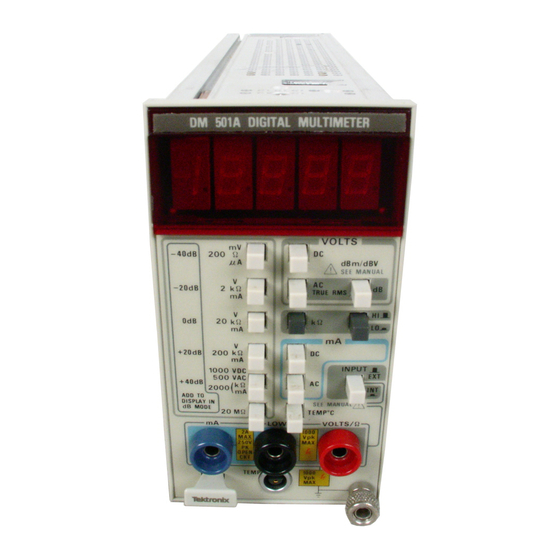
Operating Instructions-OM S01A Release latch. Pull to remove plug-in. CONTROLS AND CONNECTORS .& Refer to General O perating Information. 4-1/2 digit LED readout with decimal poin t positioned by the selected range push button switch. Gen eral Operating Information With the OM SOlA properly installed in the power Range selector push button switches for volts, module and the power switch on, allow thirt y minutes ohms, current or decibel measuremenL... - Page 21 Operating Instructions-OM SOlA FIg. Controls and connectors. 2�2. English REV A AUG 1980...
- Page 22 Operating Instructions-OM SOiA � When the OM 501A is shipped, the 0 d B reference is mW into 600 0 (0.7746 V)" A 0 dB reference of 1 V is also available through an internal jumper (see the Calibration To help eliminate shock hazard from voltages...
- Page 23 Seal the carton with shipping tape or an in dustrial stapler. Repack aging I nform ation If this Tektronix instrument is to be shipped t o a Tektronix Service Center for service or repair, attach a tag The carton test strength for this instrument is 200...
- Page 24 Verso Filler Page...
- Page 25 501A Japanese 2-3...
- Page 26 Verso Filler Page...
-
Page 27: Theory Of Operation
501 A Section 3-0M TH EORY OF OPERATION A de voltage applied to the VOL TS/o connector passes Introduction through switches S l - C and Sl-E to the top of the This section of the m a n u a l describes t h e circuits attenuator resistor series network conSisting of R 1 1 12A, necessary to display i n digital form. - Page 30 Theory of Operation-OM 501 A to the Analog Converter pi n In ac current The O hms Reference Current Source. ( U 1 60 1 15). 0 1 4 1 5 function. the rnA ac front-panel switch (Sl-l pin associated circuitry, generates a fJ.A reference closed.
- Page 31 Theory of Operation-OM SOlA Circuit protection tathe ohmmeter function is provided The basic sensitivity of the aid converteris2 Vfull scale by posistor RTll02 and clamping diodes C R 1 516 and indication, which is set by R 1505 (2 Vdc). The 200 mV full C R 1 5 1 8.
- Page 33 Theory of O peration-OM SOIA integrator to go positive with respect to (see Fig. 3-7), Display Driver then returns it to potential, stopping only when the Display driver U 1 805 is a bcd to 7-segment decoder. L0120 (UI60 1 ) comparator changes state. The count is i n The bcd digit information is decoded by U 1 805 and single clock times.
- Page 34 Theory of Operation-OM SOlA The output voltage tram T1301, pins 1 0 and 1 2, i s Power Supply rectified by C R 1 424 and CR1426 a n d applied t o U 1 43 1 , The 25 Vac input to isolation transformer T130l is This three-terminal regulator provides the + 5 V source.
-
Page 35: Calibration Procedure
Also, use this procedure t o Services Available determine acceptability of performance in a n incoming Tektronix, I nc. provides complete i nstrument repair i nspection facility. and adjustment at local field service centers and at the factory service center. -
Page 36: Front Panel Input Accuracy Checks
Calibration Procedure-OM SOlA Performance Check Procedure 4-1 (cont) Table Requirements Example Description Performance Applications Electro SCientific I ndustries, Inc. Resistance Standard Range. 0 to 20 MQ; accuracy. Ohmmeter accuracy ±O.OS%. check. Model DB 62 Dekabox. Temperature Bath Range. -620 C to +2400 C; Temperature probe Neslab I nstruments Inc., Model UL T-80 Bath Circulator... - Page 37 Calibration Procedure-OM SOlA Performance Check Procedure h. Press the mV range push button. d. Press the m V range push button. i. Set the dc voltage calibrator for V output. e. Set the ac calibrator for V ac rms output at either 10.00 Hz, ±0.2 Hz.
- Page 38 Calibration Procedure- OM SOiA Performance Check Procedure 6. Check Ohms Accuracy e. Remove the AC current source and all connections. a. Connect a resistance standard to t h e VOL TSIn and lOW connectors. b. Press the kQ function push button and the ap Check Temperature Accuracy propriate H I or LO push button as indicated i n Table 4-6.
- Page 39 Calibration Procedure-DM SOlA Performance Check Procedure Table 4-2 FRO N T PANEL D C VOLTAGE ACCURACY D I SPLAY LIMITS Dc Call brati o n Ambient Temp. Range Ambient Temp. Range Range Voltage +18°C to +28° C Q O C to + 1 8 ° C, +28'C to +50' C 200 mV 1 90.00 mV 190.13 to 189.87...
- Page 40 Calibration Procedure--DM SOlA Perf ormance Check Procedure Table 4-4 F R O N T PANEL dBm ACCURACY Calibration Frequency, 20 Hz to 20 kHz, +20 dB to - 1 5 d B 20 Hz lo 1 0 kHz, - 1 5 dB to -20 d B DISPLAY LIMITS Calibration Ambient Temp.
- Page 41 Calibration Procedure-OM SOlA Performance Check Procedure Table 4-6 FRONT PANEL RESISTANCE ACCURACY D I SPLAY LIMITS Ambient Temp. Range Ambienl Temp. Range Range Resistance +18° C to +28° C O° C to +18° C, +28°C +SO° C 200 0 1 90.00 0 1 90.32 10 1 90.62 1 89.68...
-
Page 42: Temperature Limits
Cali bration Procedure-OM SOlA Performance Check Procedure Table 4-8 F R O N T PANEL AC CURR ENT ACCURACY DISPLAY L I M I T S Ambient Temp. Range Ambient Temp. Range +18° C 10 +28° C Range Current O ° C to + 1 8 ° C, +28°C to +50°C 200 /-IA 190.00 /-IA 1 9 1 . - Page 43 Calibration Procedure-OM SOiA Performance C heck Procedure Table 4-11 REAR INTERFACE AC VOLTAGE ACCURACY DISPLAY LIMITS Ac Calibration Ambient Temp. Range Ambient Temp. Range Range Voltage +18' C to +28'C O ' C to + 1 8 ' C, +28'C to +SO'C 40 Hz to 20 to 40 Hz, 40 Hz t o...
- Page 44 Calibration Procedure-OM SOiA Performance Check Procedure Table 4-13 R E A R INTERFACE dBm ACCURACY Calibration Frequency, 20 Hz to 20 kHz, +20 to -15 20 H z to 10 kHz, - 1 5 to -20 DISPLAY L I M I T S Ambient Temp.
-
Page 45: Adjustment Procedure
The test eqUipment (or equivalent) listed in Table 4-1 is b. Connect a shorting strap from the LOW connector required for adjustment of the DM 501A. Specifications to the VOLTSm connector o n the front panel of the given for the test eqUipment are the minimum necessary OM SOlA. - Page 46 Calibration Procedure- O M 501A Adjustment Procedure k. Set the voltage calibrator to a mini m u m voltage. NOTE The adjustment of the Vdc range interacts with the I. Remove connections. setting of the m V range but not vice-versa. b.
- Page 47 Calibration Proced ure-OM S01A Adjustment Procedure d. Set the resistance standard for 19.000 kO. b. Connect the temperature probe to the front panel TEMP connector. e. Connect the resistance standard between the VOL TS/O and LOW input connectors. c. Press the TEMpoC function push button. f.
- Page 48 Verso Filler Page...
-
Page 49: Identification And Description
CALIBRATION PROCEDURE FOR DIGITAL MULTIMETER, TEKTRONIX TYPES DM 501 AND DM 501A WITH DC HIGH VOLTAGE PROBE, BALLANTINE, MODEL 10800C; JOHN FLUKE, MODEL 80K-40;AND TEKTRONIX, TYPE 010-0277-00 Paragraph Page SECTION IDENTIFICATION AND DESCRIPTION Test instrument identification ......Forms, records, and reports ........ - Page 50 IDENTIFICATION AND DESCRIPTION 1. Test Instrument Identification. This bulletin provides instructions for the calibration of Digital Multimeter, Tektronix, Types DM 501 and DM 501A with DC High Voltage Probe, Ballantine, Model 10800C; John Fluke, Model 80K-40; and Tektronix, Type 010-0277-00.
-
Page 51: Calibration Description
20 to 40 Hz ......1.2 + 2 40 Hz to 10 kHz..... 0.7 + 2 10 to 20 kHz ......1.2 + 2 Tektronix, Type DM 501A Dc voltage Range: 0 to 1000 V ( in 5 ranges) Accuracy: ±(% of reading + % of FS) -
Page 52: Section Ii Equipment Requirements
TB 9-6625-1957-35 1. Calibration Description - Continued Table Test instrument parameters Performance specifications Tektronix, Type DM 501A - Continued Resistance Range: 0 to 20 MΩ (in 5 ranges) Accuracy: ±(% of reading + % of FS) Range: 200Ω through 200 kΩ (LOΩ) ....0.15 + .015 2 kΩ... -
Page 53: Preliminary Instructions
Accuracy: ±0.054% SECTION III CALIBRATION PROCESS FOR DIGITAL MULTIMETER TEKTRONIX, TYPE DM 501 6. Preliminary Instructions a. The instructions outlined in paragraphs 6 and 7 are preparatory to the calibration process. Personnel should become familiar with the entire bulletin before beginning the calibration. -
Page 54: Equipment Setup
TB 9-6625-1957-35 7. Equipment Setup WARNING HIGH VOLTAGE is used or exposed during the performance of this calibration. DEATH ON CONTACT may result if personnel fail to observe safety precautions. REDUCE OUTPUT(S) minimum after each step within performance check where applicable. a. - Page 55 TB 9-6625-1957-35 Figure 1. Tektronix, Type DM 501 - left side view. 9. Resistance a. Performance Check (1) Connect calibrator OUTPUT to TI INPUT HI and LO terminals. (2) Set RANGE/FUNCTION switch to 200K OHMS. (3) Set calibrator for a 190 kΩ output.
- Page 56 TB 9-6625-1957-35 Table 4. Resistance Calibrator Test instrument Output nominal ERROR display resistance values RANGE/FUNCTION indications switch settings ±(%) kΩ kΩ kΩ kΩ MΩ MΩ MΩ MΩ 10. Dc Current a. Performance Check (1) Connect calibrator OUTPUT to TI INPUT HI and LO terminals. (2) Set TI RANGE/FUNCTION switch to 2 DC mA.
-
Page 57: Power Supply
TB 9-6625-1957-35 Table 6. Ac Voltage Test instrument Calibrator output Test instrument Adjustments RANGE/FUNCTION voltage frequency indications (fig. 1) switch settings Voltage Frequency (AC VOLTS) 1.7872 1.8128 R70 AC CAL 17.872 18.128 C42 20 V AC COMP 178.72 181.28 C45 200 V AC COMP 446.65 453.35 C48 500 V COMP... - Page 58 Annotate and affix DA label/form in accordance with TB 750-25. SECTION IV CALIBRATION PROCESS FOR DIGITAL MULTIMETER TEKTRONIX, TYPE DM 501A 14. Preliminary Instructions a. The instructions outlined in paragraphs 14 and 15 are preparatory to the calibration process. Personnel should become familiar with the entire bulletin before beginning the calibration.
- Page 59 TB 9-6625-1957-35 16. Dc Voltage a. Performance Check (1) Press pushbuttons as listed in (a) through (c) below: (a) VOLTS DC (in). (b) 2 V range (in). (c) INPUT EXT/INT (out) (EXT). (2) Short VOLTS/Ω Ω and LOW terminals. If TI does not indicate between -.0002 +.0002, perform b(l) below.
- Page 60 TB 9-6625-1957-35 Figure 2. Tektronix, Type DM 501 A - left side view. 17. Ac Voltage a. Performance Check (1) Connect calibrator OUTPUT to TI VOLTS/Ω Ω and LOW terminals and press TI VOLTS AC TRUE RMS pushbutton. (2) Press TI range pushbutton and set calibrator output as listed in table 8. TI will indicate within the specified limits;...
- Page 61 TB 9-6625-1957-35 Table 8. Ac Voltage Test instrument Calibrator output Test instrument Adjustments range voltage frequency indications (fig. 2) pushbuttons Voltage Frequency 0.0984 0.1016 LO VACR1525 -1.8876 1.9124 2 VAC R1537 188.76 191.24 - - - 18.800 19.200 - - - 18.876 19.124 - - -...
- Page 62 TB 9-6625-1957-35 19. Dc Current a. Performance Check (1) Connect calibrator OUTPUT to TI mA and LOW terminals. (2) Press TI range pushbutton and set calibrator output as listed in table 10. TI will indicate within the limits specified. b. Adjustments. No adjustments can be made. Table 10.
-
Page 63: Final Procedure
SECTION V CALIBRATION PROCESS FOR DC HIGH VOLTAGE PROBE, BALLANTINE, MODEL 10800C, JOHN FLUKE, MODEL 80K-40, AND TEKTRONIX, TYPE 010-0277-00 22. Preliminary Instructions a. The instructions outlined in paragraphs 22 and 23 are preparatory to the calibration process. Personnel should become familiar with the entire bulletin before beginning the calibration. - Page 64 (1) Connect TI probe terminals to VOLTS/Ω Ω and LOW connectors on digital multimeter (Type DM 501A), ensuring RED or positive terminal at banana plug mates with VOLTS/Ω Ω terminal on digital multimeter. (On Type DM 501, ensure that RED or positive terminal of banana plug mates with HI terminal on digital multimeter).
- Page 65 TB 9-6625-1957-35 Set calibrator to STANDBY; then press RESET pushbutton. (5) Replace cover and screws on termination box. 25. Final Procedure a. Deenergize and disconnect all equipment and reinstall protective cover on TI. b. Annotate and affix DA label/form in accordance with TB 750-25.
Need help?
Do you have a question about the DM 501A and is the answer not in the manual?
Questions and answers