Table of Contents
Advertisement
Quick Links
This user's guide describes the characteristics, operation, and use of the MSOP-8EVM, both by itself and
as part of the MSOP-8EVM-PDK. This EVM is an evaluation board for single-channel, 14- to 16-bit,
analog-to-digital converter (ADC) devices in an MSOP-8 package. A complete circuit description,
schematic diagram, and bill of materials are included with this document.
This manual covers the operation of both the MSOP-8EVM and the MSOP-8EVM-PDK. It does not
describe the MMB0 motherboard in detail. Throughout this document, the abbreviation EVM and the term
evaluation module are synonymous with the MSOP-8EVM.
ADCPro is a trademark of Texas Instruments.
Windows is a registered trademark of Microsoft Corporation.
SBAU140A – December 2008 – Revised February 2016
Submit Documentation Feedback
MSOP-8EVM and MSOP-8EVM-PDK
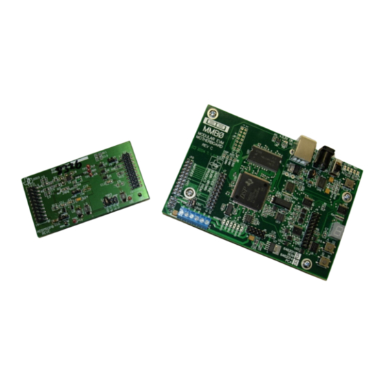
Figure 1. MSOP-8EVM (Left) and MSOP-8EVM-PDK (Right)
Copyright © 2008–2016, Texas Instruments Incorporated
SBAU140A – December 2008 – Revised February 2016
MSOP-8EVM and MSOP-8EVM-PDK
User's Guide
1
Advertisement
Table of Contents

Subscribe to Our Youtube Channel
Related Manuals for Texas Instruments MSOP-8EVM-PDK


Summary of Contents for Texas Instruments MSOP-8EVM-PDK
-
Page 1: Msop-8Evm (Left) And Msop-8Evm-Pdk (Right)
This user's guide describes the characteristics, operation, and use of the MSOP-8EVM, both by itself and as part of the MSOP-8EVM-PDK. This EVM is an evaluation board for single-channel, 14- to 16-bit, analog-to-digital converter (ADC) devices in an MSOP-8 package. A complete circuit description, schematic diagram, and bill of materials are included with this document. -
Page 2: Table Of Contents
Evaluating with the ADCPro Software ................. Appendix A Bill of Materials (BOM) and Schematic List of Figures ..............MSOP-8EVM (Left) and MSOP-8EVM-PDK (Right) ......................MMB0 Initial Setup ..................MSOP-8 EVM Board Initial Setup ............Connecting the MSOP-8EVM to the MMB0 Motherboard .................... -
Page 3: Evm Overview
The MMB0 motherboard allows the MSOP-8EVM to be connected to the computer via an available USB port. This manual shows how to use the MMB0 as part of the MSOP-8EVM-PDK, but does not provide technical details on the MMB0 itself. -
Page 4: Analog Interface
DAP Interface boards, J3 provides connection to the common power bus described in the 5-6 K Interface Board User's Guide, (SLAU104). Table 4 shows the pinout for J3. MSOP-8EVM and MSOP-8EVM-PDK SBAU140A – December 2008 – Revised February 2016 Submit Documentation Feedback Copyright © 2008–2016, Texas Instruments Incorporated... -
Page 5: J3 Pinout
MSP430. The supply voltage to these buffers is determined by JMP3 or the voltage applied to TP7. SBAU140A – December 2008 – Revised February 2016 MSOP-8EVM and MSOP-8EVM-PDK Submit Documentation Feedback Copyright © 2008–2016, Texas Instruments Incorporated... - Page 6 (shunt on pins 1-2), the reference source is the onboard reference/buffer circuit. Moving the shunt to JMP6 to pins 2-3 allows the voltage applied to the ADC (+V ) to be used as the reference source. MSOP-8EVM and MSOP-8EVM-PDK SBAU140A – December 2008 – Revised February 2016 Submit Documentation Feedback Copyright © 2008–2016, Texas Instruments Incorporated...
-
Page 7: Evm Operation
Controls external reference source (default is +2.5V from U2) JMP6 Pins 1-2 Controls reference source to ADC (default is onboard reference/buffer circuit) SBAU140A – December 2008 – Revised February 2016 MSOP-8EVM and MSOP-8EVM-PDK Submit Documentation Feedback Copyright © 2008–2016, Texas Instruments Incorporated... -
Page 8: Msop-8Evm-Pdk Kit Operation
CD). Double-click the file to run it; then follow the instructions shown. You can also use the ADCPro Update Check feature to check for newer versions of the MSOP-8EVM-PDK plug-in, once you have installed one version of it. -
Page 9: Mmb0 Initial Setup
MSOP-8EVM-PDK Kit Operation www.ti.com Setting Up the MSOP-8EVM-PDK The MSOP-8EVM-PDK contains both the MSOP-8EVM and the MMB0 motherboard; however, the devices are shipped unconnected. Follow these steps to set up the MSOP-8EVM-PDK: Step 1. Unpack the MSOP-8EVM-PDK kit. Step 2. Set the jumpers and switches on the MMB0 as shown in Figure (a) Set the Boot Mode switch to USB. -
Page 10: Msop-8 Evm Board Initial Setup
About the MMB0 The MMB0 is a modular EVM system motherboard. It is designed around the TMS320VC5507, a DSP from Texas Instruments that has an onboard USB interface. The MMB0 also has 16MB of SDRAM installed. The MMB0 is not sold as a DSP development board, and it is not available separately. TI cannot offer support for the MMB0 except as part of an EVM kit. -
Page 11: Connecting An Ac Adapter
Connecting the Power Supply The MSOP-8EVM-PDK can be operated with a unipolar +5V supply, in which case an external lab power supply can be used via J2 with the included CA-2186 cable or via J14. When the MMB0 DSP is powered properly, LED D2 glows green. -
Page 12: Laboratory Power-Supply Connection
It is not necessary to connect a +5V dc supply voltage to the +5VA terminal on J14 if the +5V/+5VA position on J13 is shorted. Figure 6. Laboratory Power-Supply Connection MSOP-8EVM and MSOP-8EVM-PDK SBAU140A – December 2008 – Revised February 2016 Submit Documentation Feedback Copyright © 2008–2016, Texas Instruments Incorporated... -
Page 13: Adcpro Software Start-Up Display Window
The program for evaluating the MSOP-8EVM-PDK is called ADCPro. This program uses plug-ins to communicate with the EVM. The MSOP-8EVM-PDK plug-in is included in the MSOP-8EVM-PDK package. -
Page 14: Ads8326Evm-Pdk Plug-In Display Window
Figure 8. ADS8326EVM-PDK Plug-In Display Window Step 3. The MSOP-8EVM-PDK plug-in window has a status area at the top of the screen. When the plug-in is first loaded, the plug-in searches for the board. You will see a series of messages in the status area indicating this action. -
Page 15: Found New Hardware Wizard, Screen
MSOP-8EVM-PDK Kit Operation www.ti.com Figure 9. Found New Hardware Wizard, Screen 1 Figure 10. Found New Hardware Wizard, Screen 2 SBAU140A – December 2008 – Revised February 2016 MSOP-8EVM and MSOP-8EVM-PDK Submit Documentation Feedback Copyright © 2008–2016, Texas Instruments Incorporated... -
Page 16: Found New Hardware Wizard, Screen 3
MSOP-8EVM-PDK Kit Operation www.ti.com Figure 11. Found New Hardware Wizard, Screen 3 Figure 12. Found New Hardware Wizard, Screen 4 MSOP-8EVM and MSOP-8EVM-PDK SBAU140A – December 2008 – Revised February 2016 Submit Documentation Feedback Copyright © 2008–2016, Texas Instruments Incorporated... -
Page 17: Found New Hardware Wizard, Screen 5
Step 8. The status area displays a connected message. The software is now ready to use. The driver installation wizard sequence should not appear again, unless you connect the board to a different USB port. SBAU140A – December 2008 – Revised February 2016 MSOP-8EVM and MSOP-8EVM-PDK Submit Documentation Feedback Copyright © 2008–2016, Texas Instruments Incorporated... -
Page 18: Evaluating With The Adcpro Software
Using the MSOP-8EVM-PDK Plug-In The MSOP-8EVM-PDK plug-ins for ADCPro provide complete control over all settings of the MSOP-8EVM devices. The MSOP-8EVM device settings can be adjusted when not acquiring data. During acquisition, all controls are disabled and settings may not be changed. -
Page 19: Clockstop Mode-Max Sclk
24 = 6MHz. The number of SCLK cycles applied to the converter is fixed, and the period of the SCLK automatically scales to reach the desired sampling rate for the given device. Figure 16. Continuous Mode—Stretched SCLK SBAU140A – December 2008 – Revised February 2016 MSOP-8EVM and MSOP-8EVM-PDK Submit Documentation Feedback Copyright © 2008–2016, Texas Instruments Incorporated... -
Page 20: Progress Bar While Collecting Data
If ADCPro stops responding while the ADSXXXXEVM-PDK is connected, unplug the power supply from the PDK. Unload and reload the plug-in before reapplying power to the PDK. MSOP-8EVM and MSOP-8EVM-PDK SBAU140A – December 2008 – Revised February 2016 Submit Documentation Feedback Copyright © 2008–2016, Texas Instruments Incorporated... -
Page 21: Appendix A Bill Of Materials (Bom) And Schematic
The device installed at location U1 depends on the EVM ordered. This device is soldered to the board for best performance. U1 may be replaced with any device listed in the EVM-compatible device data sheets found in Table SBAU140A – December 2008 – Revised February 2016 Bill of Materials (BOM) and Schematic Submit Documentation Feedback Copyright © 2008–2016, Texas Instruments Incorporated... - Page 22 Revision History ECN Number Approved Initial Release +5Va 0.47uF +5Va +LVa +5Va JMP1 0.1uF +V(adc) JMP5 SCLK JMP6 R9 33 REF3025 JMP2 22.1 R10 33 VREF OPA353N 10uF 11 12 0 ohm 13 14 15 16 17 18 19 20 10uF 10uF +V(i/o)
- Page 23 • Modified Laboratory Power-Supply Connection image. NOTE: Page numbers for previous revisions may differ from page numbers in the current version. Revision History SBAU140A – December 2008 – Revised February 2016 Submit Documentation Feedback Copyright © 2008–2016, Texas Instruments Incorporated...
- Page 24 STANDARD TERMS AND CONDITIONS FOR EVALUATION MODULES Delivery: TI delivers TI evaluation boards, kits, or modules, including any accompanying demonstration software, components, or documentation (collectively, an “EVM” or “EVMs”) to the User (“User”) in accordance with the terms and conditions set forth herein. Acceptance of the EVM is expressly subject to the following terms and conditions.
- Page 25 FCC Interference Statement for Class B EVM devices NOTE: This equipment has been tested and found to comply with the limits for a Class B digital device, pursuant to part 15 of the FCC Rules. These limits are designed to provide reasonable protection against harmful interference in a residential installation.
- Page 26 【無線電波を送信する製品の開発キットをお使いになる際の注意事項】 開発キットの中には技術基準適合証明を受けて いないものがあります。 技術適合証明を受けていないもののご使用に際しては、電波法遵守のため、以下のいずれかの 措置を取っていただく必要がありますのでご注意ください。 1. 電波法施行規則第6条第1項第1号に基づく平成18年3月28日総務省告示第173号で定められた電波暗室等の試験設備でご使用 いただく。 2. 実験局の免許を取得後ご使用いただく。 3. 技術基準適合証明を取得後ご使用いただく。 なお、本製品は、上記の「ご使用にあたっての注意」を譲渡先、移転先に通知しない限り、譲渡、移転できないものとします。 上記を遵守頂けない場合は、電波法の罰則が適用される可能性があることをご留意ください。 日本テキサス・イ ンスツルメンツ株式会社 東京都新宿区西新宿6丁目24番1号 西新宿三井ビル 3.3.3 Notice for EVMs for Power Line Communication: Please see http://www.tij.co.jp/lsds/ti_ja/general/eStore/notice_02.page 電力線搬送波通信についての開発キットをお使いになる際の注意事項については、次のところをご覧くださ い。http://www.tij.co.jp/lsds/ti_ja/general/eStore/notice_02.page SPACER EVM Use Restrictions and Warnings: 4.1 EVMS ARE NOT FOR USE IN FUNCTIONAL SAFETY AND/OR SAFETY CRITICAL EVALUATIONS, INCLUDING BUT NOT LIMITED TO EVALUATIONS OF LIFE SUPPORT APPLICATIONS.
- Page 27 Notwithstanding the foregoing, any judgment may be enforced in any United States or foreign court, and TI may seek injunctive relief in any United States or foreign court. Mailing Address: Texas Instruments, Post Office Box 655303, Dallas, Texas 75265 Copyright © 2015, Texas Instruments Incorporated...
- Page 28 IMPORTANT NOTICE Texas Instruments Incorporated and its subsidiaries (TI) reserve the right to make corrections, enhancements, improvements and other changes to its semiconductor products and services per JESD46, latest issue, and to discontinue any product or service per JESD48, latest issue.
Need help?
Do you have a question about the MSOP-8EVM-PDK and is the answer not in the manual?
Questions and answers