Table of Contents
Advertisement
Quick Links
This user's guide describes the characteristics, operation, and use of the MSOP-8EVM, both by itself and
as part of the MSOP-8EVM-PDK. This EVM is an evaluation board for single-channel, 14- to 16-bit,
analog-to-digital converter (ADC) devices in an MSOP-8 package. A complete circuit description,
schematic diagram, and bill of materials are included with this document.
This manual covers the operation of both the MSOP-8EVM and the MSOP-8EVM-PDK. It does not
describe the MMB0 motherboard in detail. Throughout this document, the abbreviation EVM and the term
evaluation module are synonymous with the MSOP-8EVM.
SBAU140 – December 2008
Submit Documentation Feedback
MSOP-8EVM and MSOP-8EVM-PDK
Figure 1. MSOP-8EVM (Left) and MSOP-8EVM-PDK (Right)
User's Guide
SBAU140 – December 2008
MSOP-8EVM and MSOP-8EVM-PDK
1
Advertisement
Table of Contents

Subscribe to Our Youtube Channel
Related Manuals for Texas Instruments MSOP-8EVM


Summary of Contents for Texas Instruments MSOP-8EVM
-
Page 1: Msop-8Evm (Left) And Msop-8Evm-Pdk (Right)
MSOP-8EVM and MSOP-8EVM-PDK Figure 1. MSOP-8EVM (Left) and MSOP-8EVM-PDK (Right) This user's guide describes the characteristics, operation, and use of the MSOP-8EVM, both by itself and as part of the MSOP-8EVM-PDK. This EVM is an evaluation board for single-channel, 14- to 16-bit, analog-to-digital converter (ADC) devices in an MSOP-8 package. -
Page 2: Table Of Contents
..............MSOP-8EVM (Left) and MSOP-8EVM-PDK (Right) ......................MMB0 Initial Setup ..................MSOP-8 EVM Board Initial Setup ............Connecting the MSOP-8EVM to the MMB0 Motherboard ....................Connecting an AC Adapter ................... Laboratory Power-Supply Connection ................ADCPro Software Start-up Display Window ................ -
Page 3: Evm Overview
The MMB0 motherboard allows the MSOP-8EVM to be connected to the computer via an available USB port. This manual shows how to use the MMB0 as part of the MSOP-8EVM-PDK, but does not provide technical details on the MMB0 itself. -
Page 4: Analog Interface
Analog Interface For maximum flexibility, the modular MSOP-8EVM is designed for easy interfacing to multiple analog sources. Samtec part numbers SSW-110-22-F-D-VS-K and TSM-110-01-T-DV-P provide a convenient, 10-pin, dual-row header/socket combination at J1. This header/socket provides access to the analog input pins of the ADC. -
Page 5: Power Supplies
Power Supplies The modular MSOP-8EVM board requires +5V dc for the analog section. This power source supplies the voltage reference (U2), the reference buffer (U4), and optionally, the ADC installed on the EVM (via JMP1). Supply voltages of +1.8V to +5V dc for the digital section are also required. When used in combination with one of the DAP Interface boards, J3 provides connection to the common power bus described in the 5-6 K Interface Board User's Guide, (SLAU104). - Page 6 (shunt on pins 1-2), the reference source is the onboard reference/buffer circuit. Moving the shunt to JMP6 to pins 2-3 allows the voltage applied to the ADC (+V ) to be used as the reference source. MSOP-8EVM and MSOP-8EVM-PDK SBAU140 – December 2008 Submit Documentation Feedback...
-
Page 7: Evm Operation
2-3, the CS (SHDN) signal is applied via J2.1. Digital I/O Buffers Single gate buffers U3, U5, and U6 are provided to ensure the safe operation of the modular MSOP-8EVM with low-voltage host controllers. The digital I/O voltage applied to these buffers via JMP3 should be set in accordance with the operating voltage of the host controller. -
Page 8: Msop-8Evm-Pdk Kit Operation
The latest software is available from Texas Instruments' website at http://www.ti.com/. The CD-ROM shipped with the MSOP-8EVM may not contain the latest software, but the ADCPro installer will check for updates when run, if connected to the Internet, and then give you the option of downloading and installing the latest version. -
Page 9: Mmb0 Initial Setup
MSOP-8EVM-PDK Kit Operation www.ti.com Setting Up the MSOP-8EVM-PDK The MSOP-8EVM-PDK contains both the MSOP-8EVM and the MMB0 motherboard; however, the devices are shipped unconnected. Follow these steps to set up the MSOP-8EVM-PDK: Step 1. Unpack the MSOP-8EVM-PDK kit. Step 2. Set the jumpers and switches on the MMB0 as shown in Figure a. -
Page 10: Msop-8 Evm Board Initial Setup
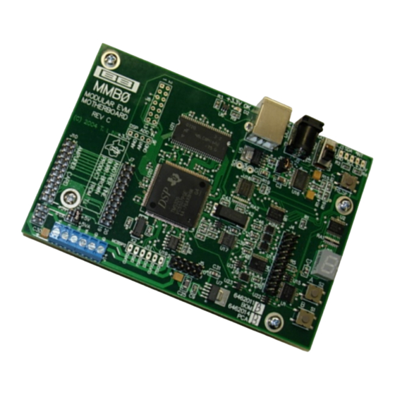
About the MMB0 The MMB0 is a modular EVM system motherboard. It is designed around the TMS320VC5507, a DSP from Texas Instruments that has an onboard USB interface. The MMB0 also has 16MB of SDRAM installed. The MMB0 is not sold as a DSP development board, and it is not available separately. TI cannot offer support for the MMB0 except as part of an EVM kit. -
Page 11: Connecting An Ac Adapter
Connecting the Power Supply The MSOP-8EVM-PDK can be operated with a unipolar +5V supply, in which case an ac adapter or a lab power supply can be used. When the MMB0 DSP is powered properly, LED D2 glows green. The green light indicates that the 3.3V supply for the MMB0 is operating properly;... -
Page 12: Laboratory Power-Supply Connection
MSOP-8EVM-PDK Kit Operation www.ti.com 6.3.2 Connecting a Laboratory Power Supply A laboratory power supply can be connected through terminal block J14 on the MMB0, as shown in Figure To use a unipolar lab power supply configuration: • Disconnect J12 on the MMB0. -
Page 13: Adcpro Software Start-Up Display Window
The program for evaluating the MSOP-8EVM-PDK is called ADCPro. This program uses plug-ins to communicate with the EVM. The MSOP-8EVM-PDK plug-in is included in the MSOP-8EVM-PDK package. -
Page 14: Ads8326Evm-Pdk Plug-In Display Window
Figure 8. ADS8326EVM-PDK Plug-In Display Window Step 3. The MSOP-8EVM-PDK plug-in window has a status area at the top of the screen. When the plug-in is first loaded, the plug-in searches for the board. You will see a series of messages in the status area indicating this action. -
Page 15: Found New Hardware Wizard, Screen
MSOP-8EVM-PDK Kit Operation www.ti.com Figure 9. Found New Hardware Wizard, Screen 1 Figure 10. Found New Hardware Wizard, Screen 2 SBAU140 – December 2008 MSOP-8EVM and MSOP-8EVM-PDK Submit Documentation Feedback... -
Page 16: Found New Hardware Wizard, Screen 3
MSOP-8EVM-PDK Kit Operation www.ti.com Figure 11. Found New Hardware Wizard, Screen 3 Figure 12. Found New Hardware Wizard, Screen 4 MSOP-8EVM and MSOP-8EVM-PDK SBAU140 – December 2008 Submit Documentation Feedback... -
Page 17: Found New Hardware Wizard, Screen 5
MSOP-8EVM-PDK Kit Operation www.ti.com Figure 13. Found New Hardware Wizard, Screen 5 Step 6. When Windows installs the software driver, the plug-in downloads the firmware to the MMB0. Step 7. Windows will display the installation wizard a second time. Again, accept the default settings. -
Page 18: Evaluating With The Adcpro Software
The MSOP-8EVM device settings can be adjusted when not acquiring data. During acquisition, all controls are disabled and settings may not be changed. When you change a setting on the MSOP-8EVM device plug-in, the setting is immediately updated on the board. -
Page 19: Clockstop Mode-Max Sclk
24 = 6MHz. The number of SCLK cycles applied to the converter is fixed, and the period of the SCLK automatically scales to reach the desired sampling rate for the given device. Figure 16. Continuous Mode—Stretched SCLK SBAU140 – December 2008 MSOP-8EVM and MSOP-8EVM-PDK Submit Documentation Feedback... -
Page 20: Progress Bar While Collecting Data
ACDPro User's Guide. Troubleshooting If ADCPro stops responding while the ADSXXXXEVM-PDK is connected, unplug the power supply from the PDK. Unload and reload the plug-in before reapplying power to the PDK. MSOP-8EVM and MSOP-8EVM-PDK SBAU140 – December 2008 Submit Documentation Feedback... -
Page 21: Appendix A Bill Of Materials (Bom) And Schematic
Appendix A www.ti.com Appendix A Bill of Materials (BOM) and Schematic Table A-1 contains a complete bill of materials for the modular MSOP-8EVM. The schematic diagram is also provided. Table A-1. Bill of Materials Designators Description Manufacturer Mfg. Part Number... - Page 22 Revision History ECN Number Approved Initial Release +5Va 0.47uF +5Va +LVa +5Va JMP1 0.1uF +V(adc) JMP5 SCLK JMP6 R9 33 REF3025 JMP2 22.1 R10 33 VREF OPA353N 10uF 11 12 0 ohm 13 14 15 16 17 18 19 20 10uF 10uF +V(i/o)
- Page 23 EVALUATION BOARD/KIT IMPORTANT NOTICE Texas Instruments (TI) provides the enclosed product(s) under the following conditions: This evaluation board/kit is intended for use for ENGINEERING DEVELOPMENT, DEMONSTRATION, OR EVALUATION PURPOSES ONLY and is not considered by TI to be a finished end-product fit for general consumer use. Persons handling the product(s) must have electronics training and observe good engineering practice standards.
- Page 24 IMPORTANT NOTICE Texas Instruments Incorporated and its subsidiaries (TI) reserve the right to make corrections, modifications, enhancements, improvements, and other changes to its products and services at any time and to discontinue any product or service without notice. Customers should obtain the latest relevant information before placing orders and should verify that such information is current and complete.
Need help?
Do you have a question about the MSOP-8EVM and is the answer not in the manual?
Questions and answers