Advertisement
Quick Links
Advertisement

Subscribe to Our Youtube Channel
Related Manuals for Texas Instruments MSP-US-TRF6901


Summary of Contents for Texas Instruments MSP-US-TRF6901
- Page 1 MSP-US/EU-TRF6901 EVM Quick Start Guide Written By: Juan Alvarez Oct - 02...
- Page 2 Table of Content • Introduction (pg. 3) • Using the EVM as: – a link demonstration tool (pg. 4) – a code development tool (pg. 7) – an RF/device level evaluation tool (pg. 9) • Additional documentation (pg. 11) • Choosing an antenna (pg. 12)
- Page 3 Starts on page • The EVM kit is offered in 2 versions: – MSP-US-TRF6901. MSP430 pre-programmed with the European ISM band – MSP-EU-TRF6901. MSP430 pre-programmed with the US ISM band • The OBJECTIVE of this document is to get you started using the EVM kit.
- Page 4 PC to another PC using a wireless link at 32 kbps. • Hardware required: – 2 MSP-US-TRF6901 (or MSP-EU-TRF6901) EVM kits – 4 antennas (See pg. 13 for how to choose an antenna) –...
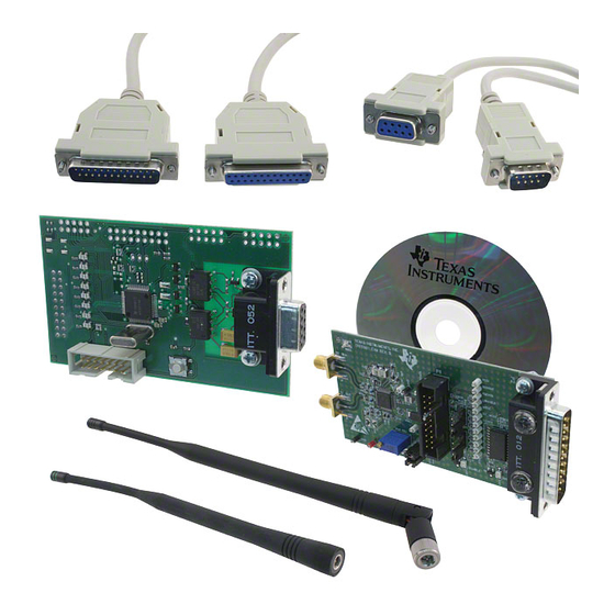
- Page 5 Demonstration setup for each ‘station’ MSP430 board (included in the kit) 4” antenna (not included in the kit) Serial Port Interface ‘A’ Parallel Port TRF6901 board (included in the kit) Plug the MSP430 board into the TRF6901 board using interface ‘A’ (per the illustration) Screw the pair of antennas to the Rx and Tx ports to the SMA connectors Connect the serial port cable to the EVM and the PC Connect a 6 to 8 V power supply to the Vcc and Gnd pins...
- Page 6 Link demonstration software start-up screen Make sure that you choose the correct serial port Press the ‘Connect to serial port’ button to start the demo after connecting the EVM to the PC using the serial port...
- Page 7 This section describes the steps required to use the EVM as a code development tool and program the MSP430 uC. • Hardware required: – 1 MSP-US-TRF6901 (or MSP-EU-TRF6901) EVM kit – 1 PC equipped with 1 serial port – 1 Power Supply –...
- Page 8 MSP-US/EU-TRF6901 MSP430 JTEG interface JTEG interface...
- Page 9 • This section describes the steps required to evaluate the TRF6901 device on a stand-alone . • Hardware required: – 1 MSP-US-TRF6901 (or MSP-EU-TRF6901) EVM kit – 1 PCs equipped with 1 parallel port – 1 Spectrum Analyzer – 1 Signal generator (or another EVM) –...
- Page 10 RF Evaluation Board Setup (Tx and Rx) Rx RF Port Tx RF Parallel Port Port Connect the parallel port between the EVM and the PC Connect a 6 to 8 V power supply to the Vcc and Gnd pins Determine what kind of evaluation you want to work on: •...
- Page 11 RF Evaluation Software Snap shots The software enables you to look at the block diagram (below) by double clicking on the white box Start up screen...
- Page 12 Additional Documentation More information available www.ti.com/ismrf You will find multiple sources of information to help you solve your inquiries, including data sheets, application notes, reference designs, development software utilities, and FAQs...
- Page 13 Choosing an Antenna • Custom built: a custom-built antenna can be used while the designer focuses on developing the system. For this case, a 4” wire can be soldered to a SMA connector. • Off-the-shelf: a designer may opt to purchase a pre fabricated tuned antenna.
- Page 14 Antenna Manufacturers • http://www.superpass.com/902 • http://www.galtronics.com/wdat -928M.html a.html • http://www.maxrad.com/ • http://www.antstar.com/ • http://www.mobilemark.com/ • http://www.aatinternational.co m/default.htm • http://www.cushcraft.com • http://www.antennafactor.com/ • http://www.hyperlinktech.com/ adocs/main.html web/antennas_900.php • http://www.dbiplus.com/produc • http://www.antennaworld.com/ ts.htm • http://www.aironet.com/ • http://www.radialllarsen.com/pr • http://www.lm- oducts/index.html electronics.com/portable.htm • http://www.rangestar.com/ •...
- Page 15 IMPORTANT NOTICE Texas Instruments Incorporated and its subsidiaries (TI) reserve the right to make corrections, modifications, enhancements, improvements, and other changes to its products and services at any time and to discontinue any product or service without notice. Customers should obtain the latest relevant information before placing orders and should verify that such information is current and complete.
Need help?
Do you have a question about the MSP-US-TRF6901 and is the answer not in the manual?
Questions and answers