Table of Contents
Advertisement
Quick Links
Thank you for requesting the MSP430F663x Sample Kit. This kit gives you an opportunity to
evaluate the first device in the MSP430 F6xx family.
This Getting Started guide reviews the contents of your kit and provides an overview for how to
quickly get started with the MSP430F6638 experimental device.
1
What is MSP430F6638? ..................................................................................................................1
2
Sample Kit Contents .......................................................................................................................2
3
Documentation Available Online ...................................................................................................2
4
Getting Started with F66xx/F56xx Development ..........................................................................2
4.1 Setting up the IDE .....................................................................................................................2
4.2 MSP-FET430UIF Installation.....................................................................................................3
4.3 MSP-TS430PZ100 USB Target Board......................................................................................3
4.3.1
On-Board Connectors....................................................................................................4
4.3.2
Jumper Settings.............................................................................................................4
4.4 Setting up a USB Code Example ..............................................................................................5
4.4.1
Attach the USB-FET Tool to the PC ..............................................................................5
4.4.2
MSP430F6638 Target Board Connections....................................................................5
4.4.3
USB Firmware for the F6638.........................................................................................5
4.4.4
Using CCS/IAR to Compile/Download/Run the Firmware .............................................6
4.5 USB Device First-Time Enumeration ........................................................................................8
4.6 Verifying USB Device Installation and Determining COM Port Assignment............................13
4.7 Running a USBCDC Demo Application using HyperTerminal ................................................14
5
Special Considerations for the MSP430F66xx Device...............................................................17
5.1 Memory Map ...........................................................................................................................17
5.2 Backup Battery Subsystem .....................................................................................................18
5.3 XT1 Oscillator..........................................................................................................................18
5.4 RTC_B Module........................................................................................................................18
6
Support and Updates....................................................................................................................19
1 What is MSP430F6638?
The MSP430F6638 is an F6xx-architecture-based MSP430 device equipped with Full Speed
USB2.0.
Please note that the included MSP430 samples are XMS430F6638 prototype device and have
not met or completed Texas Instrument's internal reliability qualification requirements. These
devices are for prototyping purposes only and not intended to be used in production systems.
Therefore, the devices are sampled on an "as is" basis and Texas Instruments makes no
warranty of fitness for a specific purpose.
SLAU316 - April 2010
Contents
Getting Started
1
Advertisement
Table of Contents

Related Manuals for Texas Instruments MSP430F663 Series


Summary of Contents for Texas Instruments MSP430F663 Series
-
Page 1: Table Of Contents
Texas Instrument’s internal reliability qualification requirements. These devices are for prototyping purposes only and not intended to be used in production systems. Therefore, the devices are sampled on an “as is” basis and Texas Instruments makes no warranty of fitness for a specific purpose. -
Page 2: Sample Kit Contents
The device is subject to errata items, as detailed in the MSP430F66xx Errata document that can be found in the product folder web page. Before proceeding, please also review the X430F66xx Experimental Device Disclaimer document, accompanying this document. 2 Sample Kit Contents One XMSP430F6638 device sample Target board with 100-pin socket (MSP-TS430PZ100USB), with eight 1x20 pin headers (four male and four female) and an USB Cable (Type A to B). -
Page 3: Msp-Fet430Uif Installation
(on a default installation) in directory: CCS: C:\Program Files\Texas Instruments\MSP430_USB_DRIVERS_v3\USB IAR: C:\ProgramFiles\IAR Systems\Embedded Workbench x.x\430\drivers\TIUSBFET\WinXP The MSP430 Hardware Tool User’s Guide (Appendix F) gives detailed instructions how to install the USB drivers. -
Page 4: On-Board Connectors
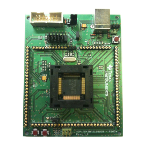
Figure 1. MSP-TS430PZ100 USB Target Board 4.3.1 On-Board Connectors • JTAG Connector: The 14-pin JTAG pin header is used to connect the USB-FET tool (MSPFET430UIF) • USB Connector: The USB type B connector on the target board is used to connect the USB cable (Type A to B) between PC and the target board 4.3.2 Jumper Settings The default jumper settings of the target board are:... -
Page 5: Setting Up A Usb Code Example
This section discusses about the two power scenarios (MSP-FET430UIF powered and USB powered) and the correct jumper settings required in both the cases. • USB Powered Scenario (default jumper setting): Connect pin 3-2 of JP3 to indicate to the MSP-FET430UIF that external on-board power is used. Close jumper JP4 connection in order to use the USB bus power. -
Page 6: Using Ccs/Iar To Compile/Download/Run The Firmware
CCSv4 .zip, that is present in the “MSP430 USB CDC+HID API Stacks” zip file, to a known location on the PC <...Your Working Directory \ USB CDCv1.19 for CCSv4 > b) Start CCSv4 Core Edition (Start Programs Texas Instruments Code Composer Studio v4 Code Composer Studio v4 Core Edition) c) If opening the example projects for the first time: Upon being asked to select a workspace directory in the “Workspace Launcher”... - Page 7 Select the USBCDC_Example1 project and Make sure that under PROJECT OPTIONS Category: FET Debugger Setup tab CONNECTION option, the Texas Instruments USB-IF or Texas Instruments LPT-IF is selected. e) Next use PROJECT REBUILD ALL to build and link the source code. f) Next use PROJECT DOWNLOAD and DEBUG to start the download and debug process.
-
Page 8: Usb Device First-Time Enumeration
h) Refer to the FET User’s Guide, FAQ on Debugging #1 if the debugger is unable to communicate with the device. Use DEBUG GO to start the application. If the device is connected to the PC for the first time with the firmware running, device installation/first time enumeration occurs. Refer Section 4.6 USB Device First-Time Enumeration When a USB device is attached to a USB host (PC), the host enumerates it;... - Page 9 3. Select "Install from a list or specific location (Advanced)" as shown below and then click "Next". 4. In the “Choose your search and installation options” window, select “Search for best driver in these locations” options and use the browse button to enter the file path that contains the USB API firmware in the combo-box.
- Page 10 <...Your Working Directory \ USB CDCv1.19 for CCSv4 (or IAR) \ USBCDC_Example1 > Once the file path has been entered in the box, click “Next” to proceed 5. Wait while the wizard searches the driver files associated Getting Started...
- Page 11 6. If Windows XP is configured to warn when unsigned (non-WHQL certified) drivers are about to be installed, the following screen will be displayed unless installing a Microsoft WHQL certified driver. Click on "Continue Anyway" to continue with the installation. If Windows XP is configured to ignore file signature warnings, no message will appear.
- Page 12 8. Windows should then display a message indicating that the installation was successful. Click "Finish" to complete the installation for the first port of the device. Getting Started...
-
Page 13: Verifying Usb Device Installation And Determining Com Port Assignment
4.6 Verifying USB Device Installation and Determining COM Port Assignment To verify if the device is properly installed and to determine the COM port assignment of the device, use Device Manager, which is Windows’ means of viewing all peripheral devices available in the system. -
Page 14: Running A Usbcdc Demo Application Using Hyperterminal
NOTE: The number assigned to the COM port (shown here as COM35) varies depending on the computer hardware configuration. Windows will check what COM ports are unused or free in the target PC and assigns that port number to the device. If the installation was successful, then unplugging and re-plugging the target board should alternatively cause the device to disappear and re-appear in the Device Manager (assuming the “Scan for new hardware”... - Page 15 Set appropriate PORT SETTINGS as shown below and press OK. Find below the ASCII set-up configurations for this demo. This window can be opened by navigating through File Properties Settings (tab) ASCII setup Getting Started...
- Page 16 Appropriate phrases entered in the HyperTerminal window help control the LED on the MSP430F6638 target board Mentioned below are the valid LED control phrases that can be typed in the HyperTerminal Window: LED ON Getting Started...
-
Page 17: Special Considerations For The Msp430F66Xx Device
LED OFF LED TOGGLE – SLOW LED TOGGLE – FAST Carriage Return/an Enter command followed by any of the above instructions results in the following: LED ON: Turns on the LED and returns the phrase "LED is ON" back to HyperTerminal LED OFF: Turns off the LED and returns the phrase "LED is OFF"... -
Page 18: Backup Battery Subsystem
Flash Memory Size 256KB Main: Interrupt vector 00FFFFh to 00FF80h Main: Code memory 047FFFh to 008000h RAM Size 16KB + 2KB Application RAM 02400h-063FFh 0023FFh-001C00h USB RAM Flash Boot Strap Loader Peripherals Information Memory 512 Byte Info A 01980h – 019FFh Info B 018FFh –... -
Page 19: Support And Updates
However it is important to know that only select RTC registers and four words of backup RAM are maintained during the above mentioned conditions. On wakeup from LPM5 or when primary supply is made available once again it is necessary to reconfigure the RTC registers to their previous state. - Page 20 IMPORTANT NOTICE Texas Instruments Incorporated and its subsidiaries (TI) reserve the right to make corrections, modifications, enhancements, improvements, and other changes to its products and services at any time and to discontinue any product or service without notice. Customers should obtain the latest relevant information before placing orders and should verify that such information is current and complete.
Need help?
Do you have a question about the MSP430F663 Series and is the answer not in the manual?
Questions and answers