Table of Contents
Advertisement
Quick Links
Advertisement
Table of Contents

Related Manuals for CYP PU-8H8HBTL


Summary of Contents for CYP PU-8H8HBTL
- Page 1 PU-8H8HBTL 8 x 8 HDMI HDBaseT™ LITE Matrix OPERATION MANUAL...
- Page 3 DISCLAIMERS The information in this manual has been carefully checked and is believed to be accurate. CYP (UK) Ltd assumes no responsibility for any infringements of patents or other rights of third parties which may result from its use. CYP (UK) Ltd assumes no responsibility for any inaccuracies that may be contained in this document.
- Page 4 SAFETY PRECAUTIONS Please read all instructions before attempting to unpack, install or operate this equipment and before connecting the power supply. Please keep the following in mind as you unpack and install this equipment: • Always follow basic safety precautions to reduce the risk of fire, electrical shock and injury to persons.
-
Page 5: Table Of Contents
CONTENTS 1. Introduction ...........6 2. Applications ...........6 3. Package Contents ........6 4. System Requirements ......7 5. Features ..........7 6. Operation Controls and Functions ..8 6.1 Front Panel ........... 8 6.2 Rear Panel ............. 9 6.3 Side Panel ...........10 6.4 Remote Control ........10 6.5 IR Cable Pin Assignment .......11 6.6 RS-232 Pin Assignment......12 6.7 RS-232 and Telnet Commands ....13... -
Page 6: Introduction
IP, RS-232, IR remote, or manual selection buttons. This single box solution will enable an installer to confidently integrate an eight zone multi-room AV system. The PU-8H8HBTL is designed to be used with the PU-514L-RX Receiver which enables the use of 2-Way IR control feature. -
Page 7: System Requirements
4. SYSTEM REQUIREMENTS HDMI equipped source devices, connect with HDMI cables or DVI equipped source, connect with DVI to HDMI cables HDMI equipped displays (TVs or monitors) or HDMI equipped AV receivers, connect with HDMI cables Industry standard CAT5e/6/7 cables HDBaseT™... -
Page 8: Operation Controls And Functions
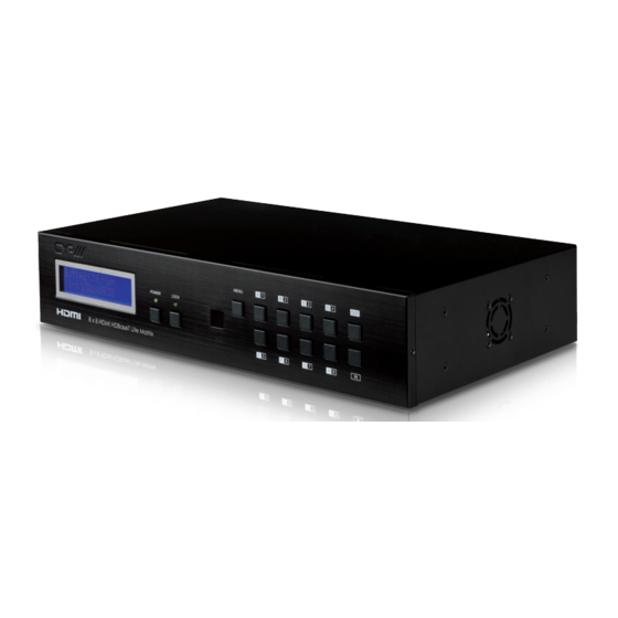
6. OPERATION CONTROLS AND FUNCTIONS 6.1 Front Panel MENU POWER LOCK LCM: Displays the setting information of each input and output setting. POWER: Press this button to power the device on/off. The LED will illuminate green when the power is on, red when it is in 'Standby' mode. -
Page 9: Rear Panel
6.2 Rear Panel IR OUT IR OUT IR OUT IR OUT IR OUT IR OUT IR OUT IR OUT IR OUT CONTROL CAT5e/6 OUT CAT5e/6 OUT CAT5e/6 OUT CAT5e/6 OUT CAT5e/6 OUT CAT5e/6 OUT CAT5e/6 OUT CAT5e/6 OUT IR IN IR IN IR IN IR IN... -
Page 10: Side Panel
DC 24V: Plug the 24 V DC power supply into the unit and connect the adaptor to an AC outlet. Warning: Please do not connect the CAT5e/6/7 cable into the receiver's CONTROL port. 6.3 Side Panel Fan Ventilator: These are air ventilation areas, DO NOT block these areas or cover it with any object. Please allow adequate space around the unit for air circulation. -
Page 11: Ir Cable Pin Assignment
6.5 IR Cable Pin Assignment IR Blaster Power 5 V IR Blaster Signal IR Extender IR Signal Power 5 V Grounding... -
Page 12: Rs-232 Pin Assignment
6.6 RS-232 Pin Assignment PU-8H8HBTL Remote Control Console Assignment Assignment Baud Rate: 19200 bps Data Bit: 8-bit Parity: None Stop Bit: 1-bit Flow Control: None... -
Page 13: Rs-232 And Telnet Commands
6.7 RS-232 and Telnet Commands Command Description A1~A8 Switch Output A to 1~8 B1~B8 Switch Output B to 1~8 C1~C8 Switch Output C to 1~8 D1~D8 Switch Output D to 1~8 E1~E8 Switch Output E to 1~8 F1~F8 Switch Output F to 1~8 G1~G8 Switch Output G to 1~8 H1~H8... -
Page 14: Telnet Control
6.8 Telnet Control Before attempting to use the telnet control, please ensure that both the Matrix (via the 'LAN /CONTROL' port) and the PC/Laptop are connected to the active networks. To access the telnet control in Windows 7, click on the 'Start' menu and type "cmd"... - Page 15 Once in the command line interface (CLI) type "telnet", then the IP address of the unit and "23", then hit enter. Note: The IP address of the Matrix can be displayed on the device's LCM monitor by pressing the Menu button twice. This will bring us into the device which we wish to control. Type "HELP" to list the available commands. Type “IPCONFIG”...
-
Page 16: Web Gui Control
6.9 Web GUI Control On a PC/Laptop that is connected to the same active network as the Matrix, open a web browser and type device's IP address on the web address entry bar. The browser will display the device's status, control and User setting pages. - Page 17 Clicking on the 'User Setting' tab allows you to reset the IP configuration. The system will ask for a reboot of the device every time any of the settings are changed. The IP address needed to access the Web GUI control will also need to be changed accordingly on the web address entry bar.
- Page 18 7. CONNECTION DIAGRAM ZONE ZONE ZONE ZONE IR In (ALL) IR OUT IR OUT IR OUT IR OUT IR OUT IR OUT CAT5e/6 OUT CAT5e/6 OUT CAT5e/6 OUT CAT5e/6 OUT IR IN IR IN IR IN IR IN IR IN IR IN Wireless Router...
- Page 19 ZONE ZONE ZONE ZONE Displays HDMI Outputs IR Out/In Receiver Units Single CAT 5e/6 Cable Model Shown: HDBaseT Lite 8×8 HDMI Matrix IR OUT IR OUT IR OUT T5e/6 OUT CAT5e/6 OUT CAT5e/6 OUT CAT5e/6 OUT IR IN IR IN IR IN MAIN 24V HDMI IN...
-
Page 20: Specifications
8. SPECIFICATIONS Video Bandwidth 225 MHz/6.75 Gbps Input Ports 8×HDMI, 9×IR Extender, 1×RS-232, 1×RJ- 45(Control), 1×Mini USB Type B (For firmware update only) Output Ports 8×CAT5e/6/7, 9×IR Blaster ESD Protection Human-body Model: ± 8kV (Air-gap discharge) ± 4kV (Contact discharge) Power Supply 24 V/6.25 A DC (US/EU standards, CE/ FCC/UL certified) - Page 21 CAT5e/6/7 Cable Specification Cable Range Pixel clock Video Data Supported Video Type rate Rate CAT5e/6/7 60 m <=225 MHz <=5.3 Gbps Up to 1080p, 60 Hz, (HD Video) 36 bits 3D(data rates lower than 5.3 Gbps or below 225 MHz TMDS clock).
-
Page 22: Acronyms
9. ACRONYMS ACRONYM COMPLETE TERM Command Line Interface Digital Theater System Digital Visual Interface EDID Extended Display Identification Data Graphical User Interface HDCP High-bandwidth Digital Content Protection HDMI High-Definition Multimedia Interface HDTV High-Definition Television Liquid Crystal Module Universal Serial Bus Video Graphics Array WUXGA Widescreen Ultra Extended Graphics Array... - Page 24 CYP (UK) Ltd., Unit 7, Shepperton Business Park, Govett Avenue, Shepperton, Middlesex, TW17 8BA Tel: +44 (0) 20 3137 9180 | Fax: +44 (0) 20 3137 6279 Email: sales@cypeurope.com www.cypeurope.com v1.00...
Need help?
Do you have a question about the PU-8H8HBTL and is the answer not in the manual?
Questions and answers