
Related Manuals for CYP PU-8H8HBTPL-4K22


Summary of Contents for CYP PU-8H8HBTPL-4K22
- Page 1 PU-8H8HBTPL-4K22 8 x 8 HDMI HDBaseT™ LITE Matrix (w. PoC, 4K resolution support, & HDCP2.2) OPERATION MANUAL...
- Page 3 DISCLAIMERS The information in this manual has been carefully checked and is believed to be accurate. CYP (UK) Ltd assumes no responsibility for any infringements of patents or other rights of third parties which may result from its use. CYP (UK) Ltd assumes no responsibility for any inaccuracies that may be contained in this document.
- Page 4 SAFETY PRECAUTIONS Please read all instructions before attempting to unpack, install or operate this equipment and before connecting the power supply. Please keep the following in mind as you unpack and install this equipment: • Always follow basic safety precautions to reduce the risk of fire, electrical shock and injury to persons.
-
Page 5: Table Of Contents
CONTENTS 1. Introduction ...........6 2. Applications ...........6 3. Package Contents ........6 4. System Requirements ......7 5. Features ..........7 6. Operation Controls and Functions ..8 6.1 Front Panel ........... 8 6.2 Rear Panel ............. 9 6.3 Side Panel ...........10 6.4 Remote Control ........11 6.5 IR Cable Pin Assignment .......11 6.6 RS-232 Protocol ........12 6.7 RS-232 and Telnet Commands ....12... -
Page 6: Introduction
3D TV and 3D source. This matrix features control via manual selection buttons, IR, RS-232, Telnet or Web GUI. CYP provide control drivers for all the major control systems. This unit also supports UART RS232 pass-through to the receivers. -
Page 7: System Requirements
1080p signals can be transmitted up to 60m via CAT5e/6/6a/7 PoC (Power over Cable) feature available on compatible receivers only Features bi-directional IR from input and output locations The PU-8H8HBTPL-4K22 can be controlled via RS-232, remote control, on-panel control and IP Control (Telnet & Web GUI) 2U Size Design... -
Page 8: Operation Controls And Functions
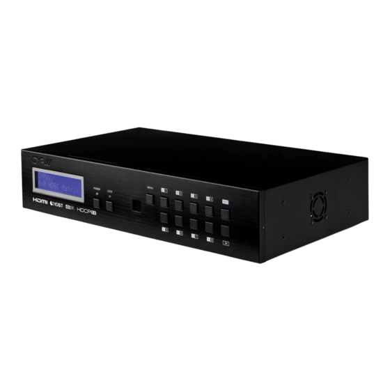
6. OPERATION CONTROLS AND FUNCTIONS 6.1 Front Panel MENU POWER LOCK LCM : Displays the setting information of each input and output setting. POWER: Press this button to power the device ON/OFF. The LED will illuminate green when the power is on, red when it is in 'Standby' mode. -
Page 9: Rear Panel
6.2 Rear Panel IR OUT IR OUT IR OUT IR OUT IR OUT IR OUT IR OUT IR OUT IR OUT CONTROL CAT5e/6 OUT CAT5e/6 OUT CAT5e/6 OUT CAT5e/6 OUT CAT5e/6 OUT CAT5e/6 OUT CAT5e/6 OUT CAT5e/6 OUT POE 24V IR IN IR IN IR IN... -
Page 10: Side Panel
HDMI IN 1~8: Connect to the HDMI input source devices such as a DVD player or a Set-top Box with HDMI cable or DVI to HDMI cable. DC 24V MAIN POWER: Plug the 24 V DC power supply into the unit and connect the adaptor to an AC outlet. -
Page 11: Remote Control
6.4 Remote Control POWER: Press this button to switch on the device or set it to standby mode. IN: Input ports selection 1~8. OUT: Output ports selection A~H. 6.5 IR Cable Pin Assignment IR Blaster Power IR Signal IR Extender IR Signal Power Ground... -
Page 12: Rs-232 Protocol
6.6 RS-232 Protocol MATRIX REMOTE CONTROLLER Assignment Assignment ► ◄ Baud Rate: 115200bps Data bit: 8 bits Parity: None Flow Control: None Stop Bit: 1 6.7 RS-232 and Telnet Commands COMMAND DESCRIPTION PARAMETER Switch output A to input N. N=1~8 Switch output B to input N. - Page 13 COMMAND DESCRIPTION PARAMETER IPCONFIG Display the current IP configuration NONE RSTIP Set IP configuration to DHCP None Power off None Power on None STOREN Store current I/O to position N N=1~8 SHOWN Show current port N I/O position N=1~8 PRESETN Preset the store I/O position N N=1~8 NameN N1...
-
Page 14: Telnet Control
6.8 Telnet Control Before attempting to use the Telnet control, please ensure that both the Matrix (via the 'LAN /CONTROL' port) and the PC/Laptop are connected to the same active networks. To access the Telnet control in Windows 7, click on the 'Start' menu and type "cmd"... - Page 15 This will bring us into the unit which we wish to control. Type "help" to list the available commands. Note: Commands will not be executed unless followed by a carriage return. Commands are case-insensitive. If the IP is changed then the IP Address required for Telnet access will also change accordingly.
-
Page 16: Webgui Control
6.9 WebGUI Control On a PC/Laptop which is connected to an active network system, open a web browser and type device’s IP address (available from LCM monitor or OSD menu) on the web address entry bar. The browser will display the device’s Switch, Data Routing, EDID Settings and System Settings. - Page 17 Click on 'EDID Settings' page to Setting EDID mode or update EDID. Click on 'System Settings' to control power on / off, Network status setting and reset to default settings. Note: It will need to click on save button once you finished network parameters setting.
-
Page 18: Connection Diagram
7. CONNECTION DIAGRAM ZONE ZONE ZONE ZONE Power Link Power Link Power Link Power Power Link IR 1 IR 2 IR 1 IR 2 IR 1 IR 2 IR 1 IR 2 Extender Blaster RS232 Out Extender Blaster RS232 Out Extender Blaster RS232 Out CAT5e/6 In... - Page 19 ZONE ZONE ZONE Displays HDMI Outputs IR In/Out Link Power Link Power Link Power Link Receiver Units IR 1 IR 2 IR 1 IR 2 IR 1 IR 2 IR 1 IR 2 Extender Blaster RS232 Out Extender Blaster RS232 Out Extender Blaster RS232 Out Extender Blaster...
-
Page 20: Specifications
8. SPECIFICATIONS 8.1 Technical Specifications Video Bandwidth 300 MHz/9 Gbps Input Ports 8×HDMI, 9×IR (3.5mm), 1×RS-232 (9-pin D-sub), 1×Control (RJ-45), 1×USB (Service only) Output Ports 8×CAT5e/6/7, 9×IR (3.5mm) Video Resolutions 480i~1080p@24/50/60, 4K@24/25/30, 4K@50/60 (YUV420) & VGA~WUXGA IR Frequency 30~50 kHz Baud Rate 115200 bps Power Supply... -
Page 21: Supported Resolutions
8.2 Supported Resolutions Resolution Input Output 640×480@60 720×480@60 720×576p@50 800×600@60 1024×768@60 1280×720@50 1280×720p@50 1280×720p@60 1280×1024@60 1600×1200@60 1920×1080i@50 1920×1080i@60 ... -
Page 22: Acronyms
9. ACRONYMS ACRONYM COMPLETE TERM CAT5e Category 5 Cable CAT6 Category 6 Cable CAT7 Category 7 Cable Command Line Interface Digital Theater System Digital Visual Interface Graphical User Interface HDCP High-bandwidth Digital Content Protection HDMI High-Definition Multimedia Interface HDTV High-Definition Television Infrared Liquid Crystal Module Power over Cable... - Page 24 CYP (UK) Ltd., Unit 7, Shepperton Business Park, Govett Avenue, Shepperton, Middlesex, TW17 8BA Tel: +44 (0) 20 3137 9180 | Fax: +44 (0) 20 3137 6279 Email: sales@cypeurope.com www.cypeurope.com v1.00...
Need help?
Do you have a question about the PU-8H8HBTPL-4K22 and is the answer not in the manual?
Questions and answers