
Related Manuals for CYP PUV-442-4K22


Summary of Contents for CYP PUV-442-4K22
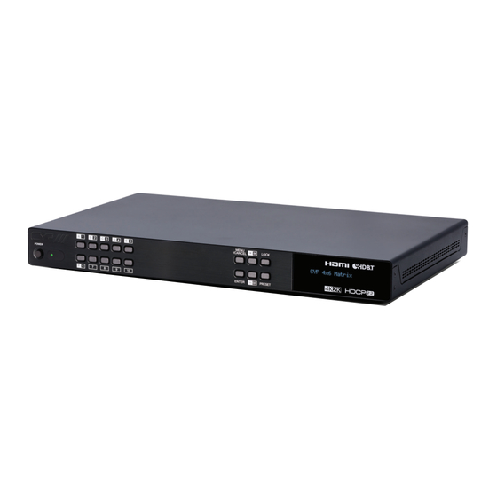
- Page 1 PUV-442-4K22 4 x 6 HDMI HDBaseT™ Matrix with Audio Matricing (4K, HDCP2.2, HDMI2.0, PoH, LAN, OAR, 100m) OPERATION MANUAL...
- Page 3 DISCLAIMERS The information in this manual has been carefully checked and is believed to be accurate. CYP (UK) Ltd assumes no responsibility for any infringements of patents or other rights of third parties which may result from its use. CYP (UK) Ltd assumes no responsibility for any inaccuracies that may be contained in this document.
- Page 4 SAFETY PRECAUTIONS Please read all instructions before attempting to unpack, install or operate this equipment and before connecting the power supply. Please keep the following in mind as you unpack and install this equipment: • Always follow basic safety precautions to reduce the risk of fire, electrical shock and injury to persons.
-
Page 5: Table Of Contents
CONTENTS 1. Introduction ...........6 2. Applications ...........6 3. Package Contents ........7 4. System Requirements ......7 5. Features ..........8 6. Operation Controls and Functions ..9 6.1 Front Panel ........... 9 6.2 Rear Panel ...........10 6.3 Side Panel ...........12 6.4 Remote Control ........13 6.5 OLED Menu ..........14 6.6 IR Cable Pin Assignment .......15 6.7 RS-232 Protocol ........15... -
Page 6: Introduction
1. INTRODUCTION This 4×6 HDMI and HDBaseT Matrix supports routing and transmission of video (resolutions up to 4K@60Hz w/ HDMI 2.0 & HDCP 2.2) and audio (multi-channel digital/stereo analogue) while providing flexible control via IR, RS-232, Telnet or WebGUI. As many as four UltraHD sources may be routed to any of six destinations, four via single Cat.5e/6/7 cables (up to 100m at 1080p or up to 60m at 4K@30Hz) and two via HDMI 2.0 outputs. -
Page 7: Package Contents
3. PACKAGE CONTENTS 1× 4 by 6 HDMI and HDBaseT Matrix with Audio Matrixing 1× Remote Control (CR-163) 2× IR Extender Cable 2× IR Blaster Cable 2× 24V/6.25A DC Power Adaptor 2× Power Cord 1× Rack Ear Set 1× Operation Manual 4. -
Page 8: Features
5. FEATURES HDMI 2.0, HDCP 1.4 and HDCP 2.2 compliant Routes 4 HDMI sources to 6 displays using 4 HDBaseT outputs and 2 independent or mirrored HDMI outputs HDBaseT 5-Play™ convergence: High-Definition video and audio, 100BaseT Ethernet, 48v PoH (Power over HDBaseT) and control (Bi- directional IR &... -
Page 9: Operation Controls And Functions
6. OPERATION CONTROLS AND FUNCTIONS 6.1 Front Panel POWER: Press this button to power the unit on or place it into stand- by mode. Note: Network functionality and PoH (if the second power supply is connected) remain active when the unit is in stand-by mode. POWER LED: This LED will illuminate GREEN to indicate the unit is on and receiving power. -
Page 10: Rear Panel
-/OUT: Within the menu, this button moves you down within the menu tree. Otherwise, this button starts routing mode and allows you to begin your output destination selections. PRESET: Press this button to recall saved presets. A maximum of 8 presets can be stored in the unit. - Page 11 CAT5e/6 OUT & IR IN A~D: Connect the Cat.5e/6 outputs via an appropriate cable to the input ports of compatible HDBaseT receivers for HDMI audio/video and IR/RS-232 control signal transmission. In order for an IR signal to be transmitted along with the HDMI signal an IR extender must be connected to the associated IR In port.
-
Page 12: Side Panel
RS-232: Connect directly to your PC/laptop to send RS-232 commands to control the unit (refer to section 6.7). LAN: Connect to an active Ethernet network to allow for Telnet and WebGUI control of the matrix (refer to sections 6.9 and 6.10) as well as to share the network (including Internet, if available) with connected compatible LAN equipped HDBaseT receivers. -
Page 13: Remote Control
6.4 Remote Control POWER: Press to power the unit on or place it MUTE LOCK POWER into stand-by mode. LOCK: Press to lock/unlock the front panel of the matrix unit. MUTE: Mutes Zone Audio outputs. HDBaseT audio can only be muted when an independent, 10/J PATTERN MENU/... -
Page 14: Oled Menu
6.5 OLED Menu 1ST LEVEL 2ND LEVEL 3RD LEVEL EDID EDID Mode Independent EDID Select 1~6 (Default EDID settings) 7~12 (Sink's EDID settings) 13~16 (User's EDID settings) Network Link Status (Idle) IP Address Subnet Mask Gateway Address MAC Address DHCP mode HDMI Mirroring Output E Output F... -
Page 15: Ir Cable Pin Assignment
6.6 IR Cable Pin Assignment IR Blaster Power IR Signal IR Extender IR Signal Power Ground 6.7 RS-232 Protocol MATRIX REMOTE CONTROLLER Assignment Assignment ► ◄ Baud Rate: 115200bps Data Bits: 8 Parity: None Flow Control: None Stop Bits: 1... -
Page 16: Rs-232 And Telnet Commands
6.8 RS-232 and Telnet Commands 6.8.1 Command Syntax The RS-232/Telnet command structure for this unit is both flexible and powerful, and allows for multiple parameters to be set across multiple ports simultaneously within a single command transmission. This section will detail the command syntax used to send both simple (single port/ single parameter) commands as well as the more complex (multi-port/ parameter) commands. - Page 17 Multi-Slot Command Format (ZoneAvPair) The ZoneAvPair command allows for multiple slots on a single HDBaseT or HDMI output to be assigned the same value simultaneously. Use the following syntax to accomplish this. Note that each additional slot uses the “+” character for separation. The number of slots allowed in a single command is limited by the number of slots on that specific interface.
- Page 18 Complex Multi-Slot/Parameter Command Format (ZoneAvPair) The ZoneAvPair command can also control multiple slots with multiple parameter groupings however the syntax is slightly different. Each command can only affect a single port at a time. Each additional set of slots/parameters are separated by the “&” character. ZoneAvPair HDBT_Out {Port} Slot {Slot1}+{Slot2}+{Etc.} {Param1=Value}, {Param2=Value} &...
- Page 19 COMMAND DESCRIPTION ZoneLineOut A AudioSrc=OAR_In A Zone Audio output “A” plays OAR audio from the TV connected to HDBaseT output “A” HDMI Mirroring Command Example If you have rack (head end) based AVR’s for surround sound rooms we recommend using the HDMI outputs and the HDMI mirroring mode to easily have the audio and video sent to the AVR follow the signal sent to that zone’s TV.
- Page 20 COMMAND DESCRIPTION ExtLineOut 1 AudioSrc=OpticIn 1 Route Optical input 1 to Extended Line output “1” ExtLineOut 1 AudioSrc=CoaxIn 1 Route Coaxial input 1 to Extended Line output “1” Above are just a few example of the audio selections available. Please refer to the full command listing for all possible commands.
- Page 21 6.8.3 Full Command List COMMAND DESCRIPTION Help Display all available commands. (Except hidden commands.) Display all available commands. (Except hidden commands.) Help {Command} Detailed description of the specified command. ? {Command} Detailed description of the specified command. SaveMuteSetting ? Display the current Save Mute Setting configuration.
- Page 22 COMMAND DESCRIPTION ZoneLineOut M Bass=XXX Set the bass value for a zone line output. M = A~D XXX = -12~+12 (units: dB) ZoneLineOut M Volume=XXX Set the volume for a zone line output. M = A~D XXX = 0 ~ -100 (units: dB) ZoneLineOut M Volume=Fast XXX Adjust the volume of a zone line output in large steps (2dB steps).
- Page 23 COMMAND DESCRIPTION ZoneLineOut M Name={NameString} Set the verbose name of a zone line output. Maximum 32 characters. M = A~D Note: Can only rename one port at a time. Multi-port is not supported. ExtLineOut M AudioSrc=XXX Set the audio source for an extended line output.
- Page 24 COMMAND DESCRIPTION ExtLineOut M Volume=Fast XXX Adjust the volume of an extended line output in large steps (2dB steps). M = 1~2 XXX = “Up” or “Down” ExtLineOut M Volume=Slow XXX Adjust the volume of an extended line output in small steps (0.5dB steps).
- Page 25 COMMAND DESCRIPTION HDMI_Out M AudioSrc=XXX Set the audio source for an HDMI output. M = E~F Available XXX values: HDMI_In n [n = 1~4] OpticIn n [n = 1] CoaxIn n [n = 1] AnalogIn n [n = 1~2] OAR_In n [n = A~D] FollowVideo HDMI_Out M Mute Mute an HDMI output’s audio.
- Page 26 COMMAND DESCRIPTION HDMI_Out M Status Display the status & properties of an HDMI output including audio/ video matrix. M = E~F HDMI_Out M Name={NameString} Set the verbose name of an HDMI output. Maximum 32 characters. M = E~F Note: Can only rename one port at a time.
- Page 27 COMMAND DESCRIPTION HDBT_Out M VideoSrc=Default Reset the video source of an HDBaseT Tx output to the factory default. M = A~D HDBT_Out M Status Display the status & properties of an HDBaseT output including audio/video matrix. M = A~D HDBT_Out M Name={NameString} Set the verbose name of an HDBaseT output.
- Page 28 COMMAND DESCRIPTION Enter light stand-by mode. (RS-232, Ethernet and PoH functionality is still active.) Turn the power on. Enter deep stand-by mode. (Only RS-232 functionality is still active.) Report the current power status. PRESET Save M Save the current A/V routing as a preset.
- Page 29 COMMAND DESCRIPTION EDID HDMI_In M=XXX Set the EDID source for a single HDMI port. M = 1~4 Available XXX values: 1~6 [Factory EDIDs] 7~12 [Connected sink EDIDs] 13~16 [User EDIDs] EDID M Name={NameString} Set the verbose name of a user EDID slot.
- Page 30 COMMAND DESCRIPTION ZoneAvPair HDBT_Out M Slot N VideoSrc=XXX Assign a video source to a Zone A/ V Pair slot on an HDBaseT output. M = A~D N = 1~10 Available XXX values: HDMI_In n [n=1~4] ZoneAvPair HDBT_Out M Slot N Load Load and activate the contents of a Zone A/V Pair slot on an HDBaseT output.
- Page 31 COMMAND DESCRIPTION ZoneAvPair HDMI_Out M Slot N Load Load and activate the contents of a Zone A/V Pair slot on an HDMI output. M = E~F N = 1~10 IR_Route HDBT_Out M0 M1 M2 Select the IR source(s) for an HDBaseT output.
- Page 32 COMMAND DESCRIPTION IR_Route IR_Out M0 M1 M2 Select the IR source(s) for an IR Output jack (next to each HDMI input). M0 is the output port index. M1 is the function to use. M2 is the IR input source. M0 = 1~4 (supports multiple port selection by using “+”.) Available M1 values: Add [Add M2 source to M0]...
-
Page 33: Telnet Control
6.9 Telnet Control Before attempting to use Telnet control, please ensure that both the unit and the PC/Laptop are connected to the same active networks. To access Telnet in Windows 7, click on the “Start” menu and type “cmd” in the search field, then press “Enter”. - Page 34 Once in the CLI (Command Line Interface) type “Telnet” followed by the IP address of the unit and “23”, then hit “Enter”. This will connect us to the unit we wish to control. Type “help” to list the available commands. Note: Commands will not be executed unless followed by a carriage return.
-
Page 35: Webgui Control
6.10 WebGUI Control Install the Device Discovery Tool Please obtain the Device Discovery software from your authorised dealer and save it in a directory where you can easily find it. Note: The unit’s default IP address is 192.168.1.50 Connect the unit and your PC/Laptop to the same active network and execute the Device Discovery software. - Page 36 Login to the WebGUI By default, both the Username and Password are “admin” for the WebGUI. The administrator password can be changed within the “User Config” tab of the WebGUI if desired. The above function tabs will always display on left side of the WebGUI to aid with navigation.
- Page 37 6.10.1 Video Switch This page provides video routing settings including HDCP configuration. Output and Input Routing To begin assigning a new video route, please click the button of the HDBaseT output you wish to send video to (e.g. “HDBT_Out A”) and then click on the button of the preferred HDMI input port (e.g.
- Page 38 Output and Input Naming All inputs and outputs can be renamed as required. To rename the HDBaseT output ports and HDMI input ports please click the “edit” icon ( ). Click the “Save” button to confirm the change. Note: Blank spaces (“ ”) are not allowed in names. HDMI Output Setting...
- Page 39 The two HDMI outputs (port E & port F) allow support for the maximum HDMI timing up to 18Gbps (4096×2160@60Hz) and can be used for normal source routing (listed as “Independent” within the WebGUI) and mirroring (listed as “Mirror” within the WebGUI) for local monitoring purposes or zone monitoring (e.g.
- Page 40 6.10.2 Zone Audio This advanced matrix offers a complete audio routing function. The Zone Audio ports offer analogue audio breakaway capability. The audio source, treble, bass, volume and audio delay adjustments can be set on this page. Output and Input Routing Click the buttons from left to right to choose each output’s source.
- Page 41 6.10.3 Extended Audio The Extended Audio ports offer additional analogue audio breakaway capability. The audio source, treble, bass, volume and audio delay adjustments can be set on this page. Output and Input Routing Click the buttons from left to right to choose each output’s source. Once the new source has been selected, the change will happen immediately.
- Page 42 6.10.4 HDMI Audio The audio routed to the two HDMI outputs (ports: E & F) and their associated settings are adjusted on this page. Output and Input Routing Click the buttons from left to right to choose each output’s source. Once the new source has been selected, the change will happen immediately.
- Page 43 6.10.5 HDBaseT Audio The audio routed to the four HDBaseT outputs (ports: A~D) and their associated settings are adjusted on this page. Output and Input Routing Click the buttons from left to right to choose each output’s source. Once the new source has been selected, the change will happen immediately. Audio source options include HDMI, Optical, Coaxial, Line, and OAR.
- Page 44 6.10.6 Zone A/V Pairing The zone A/V pairing function allows the end user to control the matrix, using the supplied remote control, in a customised manner while in remote rooms (zones) containing an HDBaseT receiver and IR extender. Each zone can have a different set of video/audio sources assigned to the buttons on the remote control for easy switching.
- Page 45 Video and Audio Pairing Edit Please click the “edit” icon ( ) to edit the video and audio routing settings. Once you have completed your selections press “Save”. 6.10.7 EDID Settings This matrix provides the option of six standard EDIDs, six sink sourced EDIDs and four customer uploaded EDIDs that can be assigned to each input port individually.
- Page 46 Sink EDID Download To save an existing custom EDID to your local PC please press the “Download” button next to the Customer EDID Settings item you would like to save. An EDID Download window will appear, allowing you to save the EDID file to your local PC.
- Page 47 The unit comes with the following 6 default EDIDs: FHD/2CH: 1080p/60Hz(148M), 2.0 LPCM, 8-bit colour. FHD/MCH: 1080p/60Hz(148M), 7.1 LPCM and bitstream, 8-bit colour. 4K UHD/2CH: 3840×2160p/30Hz (297M), 2.0 LPCM, deep colour (8/10/12-bit). 4K UHD/MCH: 3840×2160p/30Hz (297M), 7.1 LPCM and bitstream, Deep Colour (8/10/12-bit).
- Page 48 6.10.9 User Config The WebGUI and Telnet username/password are set on this page. Two management levels are available: “Administrator” and “General User”. The administrator username (“admin”) cannot be changed. The “Administrator” user has access to change all settings. The “General User”...
- Page 49 Click the “Download” button to save the current system configuration to your local PC. The current system configuration will be saved as XML file. The system configuration can also be restored from a saved XML file by clicking the “Choose File” button to locate the saved XML file, then clicking the “Restore”...
-
Page 50: Connection Diagram
7. CONNECTION DIAGRAM 1.5m 1.5m 1.5m 1.5m 60° 60° 60° 60° HDMI Source Devices • HDMI Input • IR Output Audio Source Devices • Analogue Audio Input • Digital Audio Input (Coaxial/Optical) Analogue Audio Outputs RS-232 RS-232 Equipped PC/Laptop DIGITAL ANALOG EXTENDED ZONE... -
Page 51: Specifications
8. SPECIFICATIONS 8.1 Technical Specifications Video Bandwidth HDMI: 600MHz/18Gbps HDBaseT: 340MHz/10.2Gbps Input Ports 4×HDMI 4×RCA [Stereo Audio] 1×Coaxial [S/PDIF Audio] 1×Optical [S/PDIF Audio] Output Ports 2×HDMI 4×Cat.5e/6/7 8×RCA [Stereo Audio] 4×RCA [Extended Stereo Audio] Control Ports 5×IR Extender 5×IR Blaster 1×RS-232 (9-pin D-sub) 1×LAN (RJ-45) Service Port... -
Page 52: Video Specifications
Silkscreen Colour Black Operating Temperature 0˚C - 40˚C/32˚F - 104˚F Storage Temperature −20˚C - 60˚C/−4˚F - 140˚F Relative Humidity 20 - 90% RH (No-condensing) Power Consumption 8.2 Video Specifications 8.2.1 Supported HDMI Resolutions Resolution (Hz) Input Output 480i@60 480p@60 ... -
Page 53: Audio Specifications
8.2.2 Maximum HDMI Cable Length HDMI Resolution Input Output 8-bit 1080p 10 meters 10 meters 12-bit 1080p 10 meters 10 meters 3840×2160@60Hz (YCbCr 4:2:0) 5 meters 5 meters 3840×2160@60Hz (YCbCr 4:4:4) 3 meters 3 meters Note: 1. 18Gbps (4K@60Hz YCbCr 4:4:4) HDMI signals will be converted to 10.2Gbps (4K@60Hz YCbCr 4:2:0) signals when output over the four HDBaseT ports. - Page 54 8.3.2 Linear PCM Audio Channels (kHz) LPCM 2.0@44.1 LPCM 5.1@44.1 LPCM 7.1@44.1 LPCM 2.0@88.2 LPCM 5.1@88.2 LPCM 7.1@88.2 LPCM 2.0@176.4 LPCM 5.1@176.4 LPCM 7.1@176.4 LPCM 2.0@32 LPCM 5.1@32 LPCM 7.1@32 LPCM 2.0@48 LPCM 5.1@48 LPCM 7.1@48 LPCM 2.0@96 LPCM 5.1@96 LPCM 7.1@96 LPCM 2.0@192 LPCM 5.1@192...
-
Page 55: Category Cable Specifications
8.4 Category Cable Specifications Cable Type Cable Length Supported Video Format Cat.5e/6 100 meters Most common Full HD video: Up to 1080p@60Hz, 36-bit colour Data rates lower than 5.3Gbps or below 225MHz TMDS clock 70 meters Full HD & Ultra HD video: 1080p@60Hz, 48-bit colour 4K@24/25/30Hz, 24-bit colour Cat.6a/7... -
Page 56: Acronyms
9. ACRONYMS ACRONYM COMPLETE TERM Cat.5e Category 5 (enhanced) Cable Cat.6 Category 6 Cable Cat.7 Category 7 Cable Command Line Interface Digital Visual Interface EDID Extended Display Identification Data Graphical User Interface High-Definition HDCP High-bandwidth Digital Content Protection HDMI High-Definition Multimedia Interface High Dynamic Range HTTP HyperText Transfer Protocol... - Page 60 CYP (UK) Ltd., Unit 7, Shepperton Business Park, Govett Avenue, Shepperton, Middlesex, TW17 8BA Tel: +44 (0) 20 3137 9180 | Fax: +44 (0) 20 3137 6279 Email: sales@cypeurope.com www.cypeurope.com v1.00...
Need help?
Do you have a question about the PUV-442-4K22 and is the answer not in the manual?
Questions and answers