
Subscribe to Our Youtube Channel
Related Manuals for Michell Instruments XTP601 Series


Summary of Contents for Michell Instruments XTP601 Series
- Page 1 XTP601 Process Oxygen Analyzer User’s Manual 97313 Issue 8.1 November 2020 (For use with firmware V1.11)
- Page 2 Please fill out the form(s) below for each instrument that has been purchased. Use this information when contacting Michell Instruments for service purposes. Product Name Order Code Serial Number Invoice Date Installation Location Tag Number Product Name Order Code Serial Number...
- Page 3 © 2020 Michell Instruments This document is the property of Michell Instruments Ltd and may not be copied or otherwise reproduced, communicated in any way to third parties, nor stored in any Data Processing System without the express written authorization of Michell Instruments Ltd.
-
Page 4: Table Of Contents
XTP601 User’s Manual Contents Safety ..........................vii Electrical Safety ......................vii Pressure Safety ......................vii Temperature Safety .....................vii Toxic Materials ......................vii Repair and Maintenance ....................vii Calibration ........................vii Safety Conformity .......................vii Equipment Ratings ......................vii Abbreviations ........................viii Warnings .......................... viii INTRODUCTION ....................1 Features ......................2 Applications ....................... - Page 5 Figure 29 Field Calibration Reset Page ..............26 Figure 30 XTP601 Cutaway Showing Major Components ..........29 Figure 31 XTP601 Lid Removal .................30 Figure 32 XTP601 Cable Entries ................31 Figure 33 Terminal Block Locations ................32 Figure 34 XTP601 Dimensional Drawings ..............39 Michell Instruments...
- Page 6 XTP601 User’s Manual Appendices Appendix A Technical Specifications ................37 Dimensions Ex version ..............39 Appendix B Modbus Register Map ................41 Appendix C Hazardous Area Certification ..............47 Product Standards ..............47 Product Standards ..............47 Global Certificates/Approvals ............47 Special Conditions............... 48 Maintenance and Installation ............
-
Page 7: Safety
Repair and Maintenance The instrument must be maintained either by the manufacturer or an accredited service agent. For Michell Instruments’ worldwide offices contact information go to www.michell.com. Calibration The recommended calibration interval for the analyzer is 3 months. Depending on the application in which the instrument is used, the calibration interval may be reduced. -
Page 8: Abbreviations
XTP601 User’s Manual Abbreviations The following abbreviations are used in this manual: Ampere alternating current bara pressure in bar (absolute) barg pressure in bar (gauge) °C degrees Celsius °F degrees Fahrenheit direct current kilogram Kilopascal pound maximum milliampere ml/min milliliters per minute millimeters parts per million psig... -
Page 9: Introduction
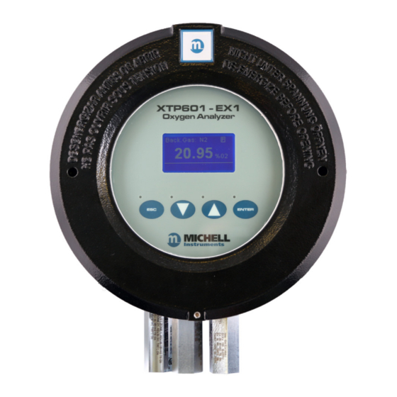
(with flame arrestors) Figure 1 XTP601 Oxygen Analyzer Versions The XTP601 Oxygen Analyzer is based on Michell Instruments’ advanced proprietary Thermo-Paramagnetic technology. It measures the percentage of oxygen in a wide range of gases, including nitrogen, hydrogen, carbon dioxide methane and biogas. -
Page 10: Features
INTRODUCTION XTP601 User’s Manual Features • The XTP601 can be supplied meeting the requirements of IEC 61508 SIL2, allowing the user to integrate the analyzer into their functional safety system. • There are 2 versions of the XTP601 available: General Purpose Analyzer with touch screen (capacitive buttons) Hazardous Area version of above with flame arrestors •... -
Page 11: Applications
-40°C to +60°C (-40°F to +140°F) (for Silicone version) -15°C to +60°C (5°F to +140°F) (for Viton version) – Standard -10°C to +60°C (14°F to +140°F) (for Ekraz version) NOTE: Silicone O-ring is not suitable for oxygen-enriched samples, i.e. O > 21%. Michell Instruments... -
Page 12: Operation
XTP601 User’s Manual OPERATION OPERATION The XTP601 is not certified for use with ambient oxygen levels that are enriched (i.e. over 21% O This analyzer has been manufactured within our quality procedures and is configured according to the purchase order. When it is installed and used as per the manufacturer’s guidelines, it will operate within the stated specification. -
Page 13: Powering Up The Analyzer
During warm-up (less than 25 minutes) a heating symbol will flash in the top right hand corner of the page. This symbol will remain until the temperature has stabilized for a minimum of 5 minutes. The analyzer will be ready for use within 30 minutes from power-up. Michell Instruments... -
Page 14: User Interface
XTP601 User’s Manual OPERATION User Interface 2.3.1 Interface Controls XTP601-EX1 Oxygen Analyzer Backlit LCD Blue LEDs ENTER Up/Down ENTER Arrow Button Button Buttons Figure 4 User Interface The diagram above illustrates the user interface, which consists of a backlit Liquid Crystal Display and 4 touch-sensitive pads that facilitate user interaction through the glass of the enclosure. -
Page 15: Esc' Button
‘ENTER’ Button Figure 8 ENTER Button ENTER ENTER button is used to select or de-select the highlighted item in a menu and to confirm a value. From the Main Page, pressing ENTER ENTER will access the Passcode Page. Michell Instruments... -
Page 16: Menu Structure
The passcode will be active for 5 minutes, so make a note of what was actually entered by going back to the passcode screen. Store this new passcode in a secure place. If you forget/lose the passcode, contact Michell Instruments for help. 97313 Issue 8.1, November 2020... -
Page 17: Menu Map
Down ( Down ( using the ) button. To return to the Main Page, either press the () button the required amount of times or press the button. Michell Instruments... -
Page 18: Front Page
XTP601 User’s Manual OPERATION 2.5.1 Front Page Figure 10 Front Page Parameter Description Background Gas Background Gas Displays the background gas that the unit was calibrated in Real oxygen reading in % Display resolution = 0.01 (if HSR=OFF) (Display resolution 0.1% when min value is >=20%) HSR oxygen reading (extrapolated quick response value of real oxygen reading) Real oxygen value is displayed in status bar (if HSR = ON) -
Page 19: Chart Page
Chart data is only stored in volatile memory and therefore is not saved. Chart interval is saved and available in a Modbus register. • Chart data is not available via serial comms as the Application Software is able to perform more sophisticated charting functions. Michell Instruments... -
Page 20: Secondary Parameters Page
XTP601 User’s Manual OPERATION 2.5.3 Secondary Parameters Page Figure 12 Secondary Parameters Page Parameter Description Sensor cell temperature display in set unit (°C, °F or Kelvin) CELL T CELL T Display Resolution = 0.1 Temperature display of Microcontroller in selected temperature unit This gives an indication of the internal GUB temperature PCB TEMP PCB TEMP... -
Page 21: Alarms Log Pages
– this is useful to check the Modbus ModBus Rx Code ModBus Rx Code communications to ensure that good data is coming through. If no code is received then ‘ --- --- ’ is displayed Michell Instruments... -
Page 22: Main Menu (Passcode Required)
XTP601 User’s Manual OPERATION Main Menu (Passcode Required) In order to change any settings on the User Menu pages, the user must enter a passcode. There is also a separate passcode for service engineers to allow factory setting changes. To access the User Menu press the ENTER ENTER button from the Main Page to call up a... -
Page 23: Settings Page
0.00 and 100.00% so that any drift below 0.00 and above 100.00 (for suppressed LIMIT 0-100% LIMIT 0-100% ON/OFF ON/OFF zero) is not visible mA outputs also limited accordingly Unit’s network address for Modbus communications Modbus ID Modbus ID 1-127 1-127 Michell Instruments... -
Page 24: Human Machine Interface (Hmi) Page
XTP601 User’s Manual OPERATION 2.7.2 Human Machine Interface (HMI) Page Figure 18 HMI Page It is possible to change parameters within the HMI, as shown below: Setting Description/Operation Options LCD contrast setting CONTRAST CONTRAST 0-100% 0-100% in 10% steps BRIGHTNESS BRIGHTNESS LCD backlit setting 0-100%... -
Page 25: Reset Page
Section 3.3. To reset/delete highlight the item using the Down ( Down ( ) button. Press ENTER ENTER to select the item, then press the () button 3 times to confirm the change. Press ENTER ENTER deselect the item. Michell Instruments... -
Page 26: Alarms Page
XTP601 User’s Manual OPERATION 2.7.4 Alarms Page Figure 21 Alarms Page The analyzer has 2 user-configurable alarms which are freely assignable within the calibrated range. The alarm relays are Single Pole Change-Over (SPCO) and are rated to 250 V, 5 A maximum. Both alarms can be set as high, low or off. Setting Description/Operation Options... -
Page 27: External Compensation Page
(excluding the 0% point as this will always be assumed to be 1 = no effect). Below 0% (< 4 mA), the compensation factor is fixed to 1. Above 100% the compensation factor is extrapolated beyond the last factor. Michell Instruments... -
Page 28: External Sensor Page
XTP601 User’s Manual OPERATION 2.7.6 External Sensor Page Figure 23 External Sensor Page This page sets up the type and range of the 4-20 mA external sensor signal that may be connected to the XTP601 for viewing in the Main Page. The range is adjustable between the MIN and MAX values but is not adjustable for Other Other... -
Page 29: Outputs Page
21.5 mA. This is to comply with the NAMUR convention and the user can choose either high or low. Setting Description/Operation Options Will drive mA output high or low if cell temperature is out of Low/High NAMUR ERR NAMUR ERR tolerance. Michell Instruments... -
Page 30: Field Cal Page
XTP601 User’s Manual OPERATION 2.7.8 Field Cal Page Figure 26 Field Cal Page Setting Description/Operation 1 POINT or 2 POINT CAL TYPE CAL TYPE Cal reference gas for 1 point cal, lower cal reference gas for 2 point cal REF GAS 1 REF GAS 1 Actual measured O for REF GAS 1... -
Page 31: Calibration
NOTE: Analyzers are calibrated in background gas suitable for the specific application. Customer's calibration gases must match the process gas. Please refer to Test Result Sheet or a Michell Instruments' representative. For range 0 to 25% the analyzer will have calibration points between 0 to 21% and will retain specification up to 23% O . -
Page 32: 1-Point Calibration
XTP601 User’s Manual CALIBRATION 1-Point Calibration This is a single point offset overlaid on top of the factory calibration. It is designed to correct minor drift and minor changes during transit. This calibration makes the unit very accurate at the calibration point and improves accuracy throughout the range. The calibration gas should be of a value that is within the main area of interest, i.e. -
Page 33: 2-Point Calibration
ENTER ENTER to highlight ACTUAL 2 value and press the () button 3 times. Ensure that the Adjusted value now equals REF Gas 2 value (±0.01%). Press ENTER ENTER to de-select. Press to return to the Main Menu. Michell Instruments... -
Page 34: Field Calibration Reset
XTP601 User’s Manual CALIBRATION The Adjusted reading will now be the same as that displayed on the Main Page and be equal to the upper calibration gas. The calibration process is complete. Return to sampling the process gas. NOTE: The analyzers leave the factory with the field calibration function turned off. -
Page 35: Installation
Maintenance and servicing of the product must only be carried out by suitably trained personnel or returned to an approved Michell Instruments’ Service Center. Before the cover is refitted, the flamepath/threaded joint between the cover and body must be thoroughly wiped... -
Page 36: Unpacking
INSTALLATION XTP601 User’s Manual Unpacking If sold separately (not part of a sampling system), the XTP601 will be supplied in a custom box which should be retained for future use (such as service return). The box contains a small carton containing 2 lid keys and 1 hex key (for the grub screw). Any cable glands supplied will also be in the smaller carton. -
Page 37: System Components
DRAWING TITLE: DRAWING No: NOR DISCLOSED TO A THIRD PARTY WITHOUT 3rd ANGLE Motherboard 0 DEC. PLACE: ± 0.5 THE CONSENT OF MICHELL INSTRUMENTS. PROJECTION 1 DEC. PLACE: ± 0.2 90486 XTP601 EX Assembly 2 DEC. PLACE: ± 0.1 HOLES Ø:± 0.1... -
Page 38: Set-Up
INSTALLATION XTP601 User’s Manual Set-Up • The XTP601 is designed to be panel or wall mounted. There are 2 bolt holes and 2 lugs (1 per corner) see Figure 11. Dimensional drawings can be found in Appendix A.1. Mount the analyzer before attempting to remove the lid. -
Page 39: Mechanical Installation
PTFE tape used must be unsintered. This is to prevent an explosion due to conventional PTFE tape acting as a potential fuel source. Unsintered PFTE tape is available as an accessory from Michell Instruments (PTFE- TAPE-02). 4.4.2... -
Page 40: Calibration Gases
INSTALLATION XTP601 User’s Manual Ideally a flowmeter and needle valve would be placed in front of the analyzer and the vent would be open to the atmosphere. 4.4.3 Calibration Gases Cylinders of the appropriate Zero and Span gases should be available for installation and commissioning. -
Page 41: Power Supply (Pl9 - Green)
The analyzer has Modbus RTU communications over RS485 protocol. • Type: Modbus RTU over RS485 • RS485: 2 wire (plus ground), half duplex • Baud Rate: 9600 • Parity: None • Data bits: 8 • Stop bits: 1 Michell Instruments... -
Page 42: Analog (4-20 Ma) Outputs And Communications (Pl5 - Green)
INSTALLATION XTP601 User’s Manual 4.5.5 Analog (4-20 mA) Outputs and Communications (PL5 - Green) Warning: Do not attempt to loop-power this instrument via the 4-20 mA output as this will irreversibly damage the main pcb. PIN 7 PIN 6 PIN 5 PIN 4 PIN 3 PIN 2... -
Page 43: Analog (4-20 Ma) Inputs And Sensor Excitation Voltage (Pl4 - Green)
If fitted in a Hazardous Area (EX) version of the XTP601 the light guide not be dismantled by the user. Dismantling the Light Guide will invalidate the the certification. NOTE: Only 1 light guide can be fitted to each analyzer. Michell Instruments... - Page 44 XTP601 User’s Manual APPENDIX A Appendix A Technical Specifications 97313 Issue 8.1, November 2020...
-
Page 45: Appendix A Technical Specifications
Digital Communications Modbus RTU over RS485 Protocol Power Supply 24 V DC; 1.5 A max Analyzer is supplied with 3 x M20 cable entries. Cable glands, Cable Entries conduit entries and blanking plugs are available as accessories. Michell Instruments... - Page 46 XTP601 User’s Manual APPENDIX A Operating Conditions 5 °C to +60 °C (+41 °F to +140 °F) Ambient Temperature 750 mbar to 1250 mbar Atmospheric Pressure Mechanical Specification Warm Up Time < 25 minutes Stabilization Time 5 minutes Dimensions 234 x 234 x 172 mm (9.2 x 9.2 x 6.7”) (w x d x h) Weight 9.7 kg (21.4 lbs) 316 &...
-
Page 47: Figure 34 Xtp601 Dimensional Drawings
NOTE 1: The GP1 model has 1/4" NPT female gas connections. EX1 and GP2 models have 1/8" NPT female gas connections. NOTE 2: Fixing mounts are NOT symmetrical. This is to ensure correct orientation. GAS IN GAS OUT Figure 34 XTP601 Dimensional Drawings M20 CABLE ENTRIES EARTHING POINT Michell Instruments... - Page 48 APPENDIX B XTP601 User’s Manual Appendix B Modbus Register Map 97313 Issue 8.1, November 2020...
-
Page 49: Appendix B Modbus Register Map
Set Clock MONTH 01–12 Set Clock YEAR 00–99 without HSR -199.00–199.99% with HSR -199.00–199.99% Cell Temperature -99.9–99.9 or equiv in F or K PCB temperature (from MSP) -99 to 99 C or equiv in F or K Atmos pressure 0–1500mBar Michell Instruments... - Page 50 APPENDIX B XTP601 User’s Manual Addr Function Access Ranges/Resolution Type mA1 Input in % (comp signal) 0.0–100.0 % mA2 Input (ext sensor signal) See Reg Details Status Flags register 0–65535 Clock HOURS/MIN 00–23 / 00–59 Clock SEC/DAY 00–59 / 01–31 Clock MONTH/YEAR 01–12 / 00–99 MINIMUM (stats)
- Page 51 -100/+20 °C, -148.0/+68.0°C, 173.0/293.0 K Tempr: -50.0/+100.0 °C, -58.0/+212.0 °F, 223.0/373.0 K Pressure: 0.0/44.1 psia, 0.0/3.0 barA, 0.0/304.0 kpa Register Type G: -200.00 to +200.00 Range = 0 to 40000 represents -200.00 to +200.00 Conversion: (RegValue – 20000)/100.00 Michell Instruments...
- Page 52 APPENDIX B XTP601 User’s Manual Register Type I – Status/Error Meaning Namur LED Displays HSR or depending on setting 0001 (system) out of range (beyond calibration range, 0002 e.g. 0–25%) 0004 Low alarm ON YELLOW 1 ON 0008 High alarm ON YELLOW 2 ON Ext Comp i/p signal error RED FLASH...
- Page 53 10 = Alarm1 is a High Alarm 3, 2 00 = Alarm2 is Inactive (off) 01 = Alarm2 is a Low Alarm 10 = Alarm2 is a High Alarm 0 = Namur Error Level Low (3.2mA) 1 = Namur Error Level High (21.4mA) Michell Instruments...
- Page 54 APPENDIX C XTP601 User’s Manual Appendix C Hazardous Area Certification 97313 Issue 8.1, November 2020...
-
Page 55: Appendix C Hazardous Area Certification
Viton: Ta =-15°C to +50°C Ekraz: Ta = 10°C to +60°C Ekraz: Ta = 10°C to +50°C Global Certificates/Approvals ATEX CML 20ATEX1038X IECEx IECEx CML 20.0018X cQPSus LR1507-6 These certificates can be viewed or downloaded from our website at: http://www.michell.com Michell Instruments... -
Page 56: Special Conditions
Maintenance and servicing of the product must only be carried out by suitably trained personnel or returned to an approved Michell Instruments’ Service Center. Flame paths are not intended to be repaired. - Page 57 XTP601 User’s Manual APPENDIX D Appendix D Quality, Recycling, Compliance & Warranty Information Michell Instruments...
-
Page 58: Appendix D Quality, Recycling, Compliance & Warranty Information
XTP601 User’s Manual Appendix D Quality, Recycling, Compliance & Warranty Information Michell Instruments is dedicated to complying to all relevant legislation and directives. Full information can be found on our website at: www.michell.com/compliance This page contains information on the following directives: •... - Page 59 APPENDIX E XTP601 User’s Manual Appendix E Analyzer Return Document & Decontamination Declaration Michell Instruments...
-
Page 60: Appendix E Analyzer Return Document & Decontamination Declaration
Has the equipment been cleaned and decontaminated? NOT NECESSARY Michell Instruments will not accept instruments that have been exposed to toxins, radio-activity or bio-hazardous materials. For most applications involving solvents, acidic, basic, flammable or toxic gases a simple purge with dry gas (dew point <-30°C) over 24 hours should be sufficient to decontaminate the unit prior to return. - Page 61 XTP601 User’s Manual NOTES Michell Instruments...
- Page 62 A PST Brand (www.ProcessSensing.com) http://www.michell.com...
Need help?
Do you have a question about the XTP601 Series and is the answer not in the manual?
Questions and answers