Icom IC-FR6100 Instruction Manual
Vhf/uhf dpmr repeater
Hide thumbs
Also See for IC-FR6100:
- Service manual (44 pages) ,
- Instruction manual (16 pages) ,
- Service manual addendum (341 pages)
Table of Contents
Advertisement
Quick Links
Download this manual
See also:
Service Manual
Advertisement
Table of Contents

Related Manuals for Icom IC-FR6100


Summary of Contents for Icom IC-FR6100
- Page 1 INSTRUCTION MANUAL VHF dPMR REPEATER iFR5100 UHF dPMR REPEATER iFR6100...
-
Page 2: Forward
CAREFULLY IC-FR5100/IC-FR6100 before attempting to operate the re- vhf/uhf dpmr repeaters designed and built with Icom’s state of the art technol- peater. ogy and craftsmanship. With proper care, this product SAVE THIS INSTRUCTION MANUAL– should provide you with years of trouble-free opera- This tion. -
Page 3: Table Of Contents
SUPPLIED ACCESSORIES PRECAUTIONS R WARNING HIGH VOLTAGE! NEVER The following accessories are supplied. attach an antenna or internal antenna connector during trans- mission. This may result in an electrical shock or burn. Handles For handles attachment Spacers R WARNING HIGH VOLTAGE! NEVER install the antenna at any place that person touch the an- tenna easily during transmission. -
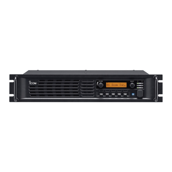
Page 4: Panel Description
PANEL DESCRIPTION ■ Front panel Function display q INTERNAL SPEAKER u MICROPHONE CONNECTOR [MIC] You can listen to received audio. This 8-pin modular jack accepts the optional micro- phone. w VOLUME CONTROL [VOLUME] (p. 7) KEEP the [MIC] connector cover over the con- Rotate to adjust the audio output level. -
Page 5: D Function Display
PANEL DESCRIPTION D Function display I C O M I n c . q SIGNAL STRENGTH ICON r COMPANDER ICON Indicates the relative signal strength level. Appears when the compander function is activated. The Compander function reduces noise compo- w LOW POWER ICON nents from the transmitted audio to provide clear communication. -
Page 6: D Accessory Connector
PANEL DESCRIPTION D Accessory connector Pin No. Pin Name Description Specification No connection — Output terminal for serial communication data. — Input terminal for serial communication data. — Output terminal for request-to-send data. — Input terminal for clear-to-send data. — No connection —... -
Page 7: Installation And Connections
INSTALLATION AND CONNECTIONS ■ Unpacking ■ Antenna connection After unpacking, immediately report any damage to For radio communications, the antenna is a critical the delivering carrier or dealer. Keep the shipping car- component, along with output power and sensitivity. tons. Select antenna(s), such as a well-matched 50 ˘... -
Page 8: Front Panel Connection
Input port for PC programming CAUTION: DO NOT short pin 1 to ground as this can damage the internal 8 V regulator. DC voltage is applied to pin 1 for microphone operation. Only Icom micro- phones are recommended. ■ Rear panel connection SP-22 EXTERNAL SPEAKER ACC CONNECTOR (p. -
Page 9: Power Supply Connection
INSTALLATION AND CONNECTIONS ■ Power supply connection ■ Mounting the repeater D Using the supplied handles Make sure the repeater’s power switch is turned OFF when connecting a DC power cable. The handles are convenient for mounting the repeater into a 19 inch rack. The handles can be installed on R WARNING! Voltages greater than 16 V DC will the repeater’s front panel. -
Page 10: Receiving And Transmitting
OPERATION ■ Receiving and transmitting D Base station operation D Repeater operation Receiving Ask your dealer for details of the repeater’s program- q Push [POWER] to turn ON the power. ming. w Set the squelch and audio levels. ➥ First, rotate [SELECT]* ➥... -
Page 11: Maintenance
If you are unable to locate the cause of a problem or The following chart is designed to help correct prob- solve it through the use of this chart, contact the near- lems which are not equipment malfunctions. est Icom Dealer or Service Center. PROBLEM POSSIBLE CAUSE SOLUTION REF. -
Page 12: Options
Icom repeater. Icom is not responsible for the destruction or damage to an Icom repeater in the event the Icom repeater is used with equipment that is not manufactured or ap- proved by Icom. -
Page 13: About Ce
ABOUT CE INSTALLATION NOTES • Compliance of base station transmitter installa- • Installation with a vertical type antenna at VHF- tions with EN50385 The installation of this equipment and it’s associated You need to consider the distances between the an- antenna should be made in such a manner as to re- tenna and any point where persons may have access. - Page 14 The RF power at the antenna input will be 12.5 watts. The dipole antenna has a forward gain of 0 dBd or CE Versions of the IC-FR5100/IC-FR6100 1.6, giving an EIRP of 20 watts. which display the “CE” symbol on the serial...
-
Page 15: About Ce
ABOUT CE DECLARATION OF CONFORMITY We Icom Inc. Japan 0168 1-1-32, Kamiminami, Hirano-ku Osaka 547-0003, Japan Declare on our sole responsibility that this equipment complies with the essential requirements of the Radio and Telecommunications Terminal Equipment Directive, 1999/5/EC, and that any applicable Essential Test Düsseldorf 16th Apr. - Page 16 < Intended Country of Use > A-6851H-1EU Printed in Japan © 2010 Icom Inc. 1-1-32 Kamiminami, Hirano-ku, Osaka 547-0003, Japan Printed on recycle paper with soy ink.
Need help?
Do you have a question about the IC-FR6100 and is the answer not in the manual?
Questions and answers