
Subscribe to Our Youtube Channel
Related Manuals for Omron Sti F3SJ-A Series

Summary of Contents for Omron Sti F3SJ-A Series
- Page 1 F3SJ-A Series (Version 2) User's Manual Safety Light Curtain Cat. No. 0997622-6F...
- Page 2 Introduction Thank you for purchasing the F3SJ Series Safety Light Curtain (hereinafter referred to as the "F3SJ" ). This is the instruction Manual describing the use of F3SJ. Always heed the following points when using the F3SJ: Be sure to have F3SJ be handled by a "Responsible Person" who is well aware of and familiar with the machine to be installed. The term "Responsible Person"...
- Page 3 •EC Type-Examination in accordance with the EU Machinery Directive, Type 4 ESPE (EN61496-1), Type 4 AOPD (prEN61496-2) •EMC Competent Body Certificate (Power supply for test: OMRON S82K) •TÜV SÜD Product Service GmbH Type Approval, Type 4 ESPE (EN61496-1), Type 4 AOPD (prEN61496-2), SIL1, 2, 3 (EN61508-1 through -7), Application: EN954-1 Category B,1,2,3,4 5.
- Page 4 PROFITS OR COMMERCIAL LOSS IN ANY WAY CONNECTED WITH THE PRODUCTS, WHETHER SUCH CLAIM IS BASED ON CONTRACT, WARRANTY, NEGLIGENCE, OR STRICT LIABILITY. In no event shall responsibility of OMRON for any act exceed the individual price of the product on which liability is asserted.
- Page 5 Performance data given in this document is provided as a guide for the user in determining suitability and does not constitute a warranty. It may represent the result of OMRON’s test conditions, and the users must correlate it to actual application requirements.
-
Page 6: Precautions On Safety
Precautions on Safety Precautions on Safety Regarding the alert symbols and meanings used for the safe uses In order to use the F3SJ safely, the precautions listed in this manual indicated by alert symbols and descriptions must be followed. Failure to follow all precautions and alerts may result in an unsafe use or operation. - Page 7 For installation Make sure to test the operation of the F3SJ after installation to verify that the F3SJ operates as intended. Make sure to stop the machine until the test is complete. Unintended function settings may cause a person to go undetected, resulting in serious injury.
- Page 8 Make sure that the F3SJ is securely mounted and its cables and connectors are properly secured. Make sure that foreign material such as water, oil, or dust does not enter the F3SJ or the connector while the cap is removed. Do not use the sensor system with mirrors in a retro-reflective configuration as shown below.Doing so may hinder detection.
- Page 9 Double or reinforced insulation from hazardous voltage must be applied to all input and output lines. Failure to do so may result in electric shock. Extension of the cable must be within a specified length. If it isn't, safety function may not work properly, resulting in danger.
-
Page 10: Precautions For Safe Use
Precautions for Safe Use Precautions for Safe Use Make sure to observe the following precautions that are necessary for ensuring safe use of the product. • Thoroughly read this manual and understand the installation procedures, operation check procedures, and maintenance procedures before using the product. •... - Page 11 Cleaning Do not use thinner, benzene, or acetone for cleaning, because they affect the product's resin parts and paint on the case. Object detection The F3SJ cannot detect transparent and/or translucent objects. F3SJ-A User’s Manual...
-
Page 12: Checking The Contents
Checking the Contents Before use, confirm that the items below were shipped with the product. If you find that an item is missing, please contact your local branch office or distributor. Product Quantity F3SJ-A main unit Emitter x 1, Receiver x 1 Top/bottom mounting brackets 4 sets Intermediate mounting brackets... -
Page 13: How To Read This Manual (Explanation Of Symbols)
How to Read This Manual (Explanation of Symbols) Indicates the description of an essential point regarding a function, such as an important point regarding operation or advice on how to use it. Indicates the page number for related content. Indicates a reference for when there is trouble, or an explanation of difficult words. F3SJ-A User’s Manual... - Page 14 F3SJ-A User’s Manual...
-
Page 15: Table Of Contents
Contents Legislation and Standards READ AND UNDERSTAND THIS DOCUMENT Precautions on Safety Precautions for Safe Use viii Precautions for Correct Use viii Checking the Contents How to Read This Manual (Explanation of Symbols) Chapter1 Overview and Specifications Basic Configuration and Names Application Examples Detect the Approach to a Hazardous Zone Using Multiple Sets in Combination... - Page 16 Interlock Function External Test Function Self-Test Function Auxiliary Output (Non-Safety Output) Resetting Lockout External Device Monitoring Function Muting System Upgrading F3SJ for Muting System Standard Muting Mode Wiring Diagrams Installation Standard for Muting Sensors Installation Example 1 of Standard Muting Mode (using 2 muting sensors) Installation Example 2 of Standard Muting Mode (using 4 muting sensors) Override Function External Test Function...
- Page 17 Setting Zone Adjacent Conditions Indicator/Input & Output Setting Auxiliary Output (Non-Safety Output) Designated Beam Output Function External Indicator Output (Non-Safety Output) Interlock Function External Device Monitoring Function Operating Range Change Operating Range Change Function Operation Monitoring Incident Light Level Display Disturbance Light Level Display Status Information Display Maintenance Information...
- Page 18 Setting Tool Mounting a Protect Bar Mounting an Environment-Resistant Case Mounting Top/Bottom Mounting Brackets Intermediate Mounting Brackets Mounting Procedure Adjustment Procedure Wiring Wiring Precautions Power Supply Unit Wiring Procedure Chapter5 Input/Output Circuit and Applications Input/Output Circuit Wiring Examples Using only F3SJ Connecting 2 Muting Sensors Connecting 4 Muting Sensors Connecting to an F3SP-B1P...
- Page 19 European Standards U.S. Federal Regurations U.S. Standards Canadian Standards Revision History F3SJ-A xvii User’s Manual...
- Page 20 F3SJ-A xviii User’s Manual...
-
Page 21: Chapter1 Overview And Specifications
Chapter1 Overview and Specifications Basic Configuration and Names Application Examples Features Indicator Display Patterns Ratings Ratings/Specifications Model Name List/Response Times Power Cable Length Compatibility with former version F3SJ-A User’s Manual... -
Page 22: Basic Configuration And Names
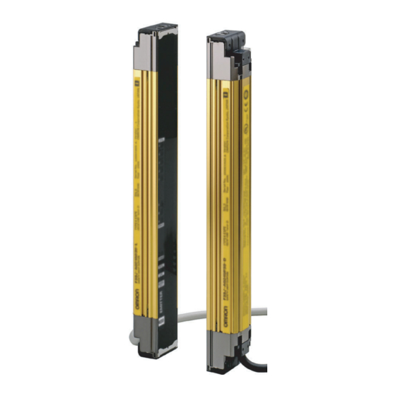
Overview and Specifications Basic Configuration and Names This section describes the system configuration and part names of the F3SJ. Beam center-line mark Beam Emitter To attach or detach the cap and power cable, remove 4 screws shown above. Indicator Receiver Connection cable (Grey) Connection cable (Black) Extension cable... - Page 23 Overview and Specifications Component Model name Description Extension Cable with connector on one F39-JC A This extension cable is used to connect the F3SJ to a cable controller with discrete terminals (e.g. F3SX, G9SA, G9SB, G9SX) or to a safety processing system (e.g. DeviceNet safety).
- Page 24 Overview and Specifications Components to be selected if necessary Component Model name Description Optional bracket Use this bracket (sold separately) for dedicated applications. p.131 Series connection cable for F39-JJR06L Required for connecting multiple sets of F3SJ in a series. It is used close contact F39-JJR15L when you wish to perform series connection with minimum length.
-
Page 25: Application Examples
Overview and Specifications Application Examples Detect the Approach to a Hazardous Zone The F3SJ should be installed where workers require frequent access in order to perform tasks such as maintenance, and where physical barriers are difficult to install. Detect the Approach of a Person Detect a Person's Limbs F3SJ-A User’s Manual... -
Page 26: Using Multiple Sets In Combination
Overview and Specifications Using Multiple Sets in Combination By installing sensors on both sides of a machine as well as in front, you can move workpieces in and out more efficiently than when a physical barrier is installed. If the sensors are aligned in a U-shape, series-connection cables can be used between sets (up to 4 sets), so that only one control device is used, drastically reducing the amount of wiring in the panel. -
Page 27: For A System That Has A Machine Within A Detection Zone
Overview and Specifications For a System that Has a Machine Within a Detection Zone When the Zone Is Fixed (Fixed Blanking Function): For a system in which a fixed facility such as a worktable or a conveyor interrupts specific beams, the fixed blanking function can be used to disable the specific beams. -
Page 28: To Notify A Person Of Proximity To A Detection Zone (Warning Zone Function)
Overview and Specifications To Notify a Person of Proximity to a Detection Zone (Warning Zone Function) This function notifies a person that he/she is getting close to a detection zone before activating the safety functions. It can be used to prevent the unintended stopping of a machine due to the approach of a person. -
Page 29: Features
Overview and Specifications Features Protective Height Available in Incremental Sizes Protective height Series Protective height Detection capability F3SJ-A 245mm to 2117mm (in 9mm increments) Dia. 14mm F3SJ-A 245mm to 2,495mm (in 15mm increments) Dia. 20mm F3SJ-A 260mm to 2,500mm (in 20mm increments) Dia. -
Page 30: Muting/Override Function Are Provided
Overview and Specifications Muting/Override Function are Provided An F3SJ by itself can operate with muting or override function without using a controller. Definition of muting function and override function p.203 F3SJ-A User’s Manual... -
Page 31: Indicator Display Patterns
Overview and Specifications Indicator Display Patterns Emitter Receiver LEVEL LEVEL LEVEL-5 (Green) LEVEL-5 (Green) LEVEL-4 (Green) LEVEL-4 (Green) 1. Incident light level LEVEL-3 (Orange) LEVEL-3 (Orange) 1. Incident light indicator level indicator LEVEL-2 (Orange) LEVEL-2 (Orange) LEVEL-1 (Orange) LEVEL-1 (Orange) ERROR-C (Red) ERROR- C (Red) 2. -
Page 32: Internal Indicator For Muting System
Overview and Specifications Indicators Description Blinking Turns ON when safety outputs are OFF. OFF-state indicator Blinking Blinks at following states: - Lockout state - One or more beams are blocked during the maintenance status ON-state indicator Turns ON when safety outputs are ON. Blinking Blinks when no beams are blocked during the maintenance status... -
Page 33: Display Patterns Of The Incident Light Level Indicator
Overview and Specifications Display Patterns of the Incident Light Level Indicator incident light level indicator Safety Output Less than Less than Less than Less than 170% or 170% 130% 100% Less than Incident light level higher 130% 100% Operation is possible with incident light level of 100% or more, but to ensure stability, operate when all incident light level indicators F3SJ-A User’s Manual... -
Page 34: Ratings
Overview and Specifications Ratings Ratings/Specifications In the model names in this table, the contain the 4-digit number indicating the protective height (mm). F3SJ-A F3SJ-A F3SJ-A F3SJ-A F3SJ-A Detection capability Opaque objects Opaque objects Opaque objects Opaque objects Opaque objects Diameter 14mm Diameter 20mm Diameter 25mm Diameter 30mm... - Page 35 Overview and Specifications F3SJ-A F3SJ-A F3SJ-A F3SJ-A F3SJ-A Input voltage Test input, interlock selection input, reset input, and muting input are all: ON voltage: 9 to 24Vs (sink current 3mA max.) OFF voltage: 0 to 1.5V , or open External device monitoring input is: ON voltage: 9 to 24Vs (sink current 5mA max.) OFF voltage: 0 to 1.5V , or open Indicators...
- Page 36 Overview and Specifications F3SJ-A F3SJ-A F3SJ-A F3SJ-A F3SJ-A Material Casing (including metal parts on both ends): Aluminum, zinc die-cast Cap: ABS resin Optical cover: PMMA resin (acrylic) Cable: Oil resistant PVC Weight (packaged) - F3SJ-A Weight (g)=(protective height) x 1.7+ α - F3SJ-A P20/F3SJ-A P25/F3SJ-A...
-
Page 37: Model Name List/Response Times
Overview and Specifications Model Name List/Response Times Response Response F3SJ-A F3SJ-A F3SJ-A F3SJ-A F3SJ-A Number of time time beams (ON to OFF) (OFF to ON) F3SJ-A0270P55 6 beams 10ms 40ms F3SJ-A0320P55 7 beams 10ms 40ms F3SJ-A0370P55 8 beams 10ms 40ms F3SJ-A0420P55 9 beams 10ms... - Page 38 Overview and Specifications Response Response F3SJ-A F3SJ-A F3SJ-A F3SJ-A F3SJ-A Number of time time beams (ON to OFF) (OFF to ON) F3SJ-A0461P14 F3SJ-A0755P20 F3SJ-A1000P25 F3SJ-A1245P30 F3SJ-A2470P55 50 beams 13ms 52ms F3SJ-A0470P14 F3SJ-A0770P20 F3SJ-A1020P25 F3SJ-A1270P30 51 beams 13ms 52ms F3SJ-A0479P14 F3SJ-A0785P20 F3SJ-A1040P25 F3SJ-A1295P30 52 beams...
- Page 39 Overview and Specifications Response Response F3SJ-A F3SJ-A F3SJ-A F3SJ-A F3SJ-A Number of time time beams (ON to OFF) (OFF to ON) F3SJ-A0884P14 F3SJ-A1460P20 F3SJ-A1940P25 F3SJ-A2420P30 97 beams 17.5ms 70ms F3SJ-A0893P14 F3SJ-A1475P20 F3SJ-A1960P25 F3SJ-A2445P30 98 beams 17.5ms 70ms F3SJ-A0902P14 F3SJ-A1490P20 F3SJ-A1980P25 F3SJ-A2470P30 99 beams 17.5ms...
- Page 40 Overview and Specifications Response Response F3SJ-A F3SJ-A F3SJ-A F3SJ-A F3SJ-A Number of time time beams (ON to OFF) (OFF to ON) F3SJ-A1307P14 F3SJ-A2165P20 144 beams 20.0ms 80ms F3SJ-A1316P14 F3SJ-A2180P20 145 beams 22.5ms 90ms F3SJ-A1325P14 F3SJ-A2195P20 146 beams 22.5ms 90ms F3SJ-A1334P14 F3SJ-A2210P20 147 beams 22.5ms...
- Page 41 Overview and Specifications Response Response F3SJ-A F3SJ-A F3SJ-A F3SJ-A F3SJ-A Number of time time beams (ON to OFF) (OFF to ON) F3SJ-A1730P14 191 beams 25.0ms 100ms F3SJ-A1739P14 192 beams 25.0ms 100ms F3SJ-A1748P14 193 beams 25.0ms 100ms F3SJ-A1757P14 194 beams 25.0ms 100ms F3SJ-A1766P14 195 beams...
-
Page 42: Power Cable Length
Overview and Specifications For series connections, use the calculations below. When 2 sets are series-connected: •Response time (ON to OFF) :Response time of primary sensor + Response time of secondary sensor 1 -1 (ms) •Response time (OFF to ON) :Response time (ON to OFF) x 4 (ms) When 3 sets are series-connected: •Response time (ON to OFF) :Response time of primary sensor + Response time of secondary sensor 2 + Response time of 3rd unit - 5 (ms) -
Page 43: Compatibility With Former Version
* To use Ver.1 and Ver.2.0(or Ver.2.1) sensors in combination, setting of Ver.1 F3SJ must be changed. For a rental console dedicated to setting change, contact Omron's sales representative. You can check a label on your F3SJ for its version as shown below. - Page 44 Overview and Specifications F3SJ-A User’s Manual...
-
Page 45: Chapter2 System Configuration And Functions
Chapter2 System Configuration and Functions How to Select a System Selection Flow Chart Combination of Functions Basic System Wiring Diagrams Interlock Function External Test Function Self-Test Function Auxiliary Output (Non-Safety Output) Resetting Lockout External Device Monitoring Function Muting System Upgrading F3SJ for Muting System Standard Muting Mode Wiring Diagrams Installation Standard for Muting Sensors... -
Page 46: How To Select A System
System Configuration and Functions How to Select a System Selection Flow Chart Required system configuration depends on functions to be used. Use the following flow chart to determine the system. Using muting function Using fixed blanking Basic system Using floating blanking Changing operating range Using/changing other function Basic system + Functional setting... -
Page 47: Basic System
System Configuration and Functions Basic System Basic system indicates the F3SJ with its default factory settings. The basic system provides basic safety light curtain functions. Most functions can be used without performing additional configuration. Wiring Diagrams Wiring using manual reset mode, external device monitoring function (Grey) Communication line (+) (Pink) Communication line (-) - Page 48 System Configuration and Functions Wiring for Auto Reset Mode Wiring the emitter’s circuit as shown below provides auto reset mode. (Grey) Communication line (+) (Pink) Communication line (-) : External test switch (connect to 0V if a switch is not required) : Lockout reset switch (connect to 24V if a switch is not required) : Load or PLC, etc.
-
Page 49: Interlock Function
System Configuration and Functions Ref.: Minimum Wiring Required to Check the Operation of the F3SJ (Wiring for auto reset mode and deactivated external device monitoring function) (Grey) Communication line (+) (Pink) Communication line (-) +24V DC Power supply Interlock Function The F3SJ turns the safety outputs OFF when its power is turned on or its beam is interrupted and holds this state until reset input is applied. - Page 50 System Configuration and Functions Manual Reset When a reset input is given while no interrupting object exists in a detection zone, the safety outputs turn ON. This allows the machine to be manually reset using a reset switch after ensuring safety, preventing unexpected startup (EN1037).
-
Page 51: External Test Function
System Configuration and Functions External Test Function This function forcibly stops the emission using an external signal. It can be used to verify that a safety system should properly stop when F3SJ is interrupted. To stop the emission, apply 9 to 24V to the emitter's test input line. The voltage must be applied for a period 4 times that of Toff or longer. -
Page 52: Auxiliary Output (Non-Safety Output)
System Configuration and Functions •Incidence of disturbance light •Failure of safety output circuit •Broken or short-circuited cable Error indication patterns and causes of errors p.186 How to reset lockout: See p.33 for basic system and p.55 for muting system For information about lockout, see p.203 Waveform of Safety Outputs When the F3SJ is receiving light, the safety outputs cyclically turn OFF as shown below to test the output circuit. -
Page 53: Resetting Lockout
System Configuration and Functions Unblocked Unblocked /Blocked Blocked Toff Safety output Toff x2 or less *1 Toff x2 or less *1 Auxiliary output 1 *1 When a reversed signal of safety output is assigned to the auxiliary output 2 by the setting tool, a delay time of the auxiliary output 2 from the safety output is Toff x 3 or less. -
Page 54: External Device Monitoring Function
System Configuration and Functions External Device Monitoring Function This function detects malfunctions, such as welding, in external relays (or contactors) that control the hazardous zone of a machine. This function constantly monitors that a specified voltage is applied to the receiver's external device monitoring input line, and enters lockout state when an error occurs. -
Page 55: Muting System
System Configuration and Functions Muting System The muting function temporarily disables the safety function of the F3SJ, keeping the safety outputs ON even if beams are blocked. This makes it possible to install safety light curtains for AGV passage, enabling both safety and productivity. -
Page 56: Upgrading F3Sj For Muting System
Through-beam or retro-reflective photoelectric sensors, proximity sensors, or limit switches can be used as muting sensors. (recommendation: OMRON E3Z series, E2E series (3-wire type), D4N series) Use 3-wire type PNP output or N.O. type contact. Two-wire type sensor cannot be used. - Page 57 System Configuration and Functions Setting Change by the Setting Tool Following functions can be configured by the setting tool. See p.81 for details. •Selecting muting mode (for the PC tool for F3SJ only) •Selecting muting range •Teaching muting beams •Specifying muting beams manually •Setting muting time limit •Enabling Interlock Function Muting Function p.81...
-
Page 58: Standard Muting Mode
System Configuration and Functions Standard Muting Mode Operation mode configured for F3SJ factory shipment.Turning muting inputs 1 and 2 ON with time difference enables muting function. For details of setting change, see Muting in Chapter 3. Muting Function p.81 Start Conditions If both of the following 2 conditions are present for the F3SJ, muting is activated. - Page 59 System Configuration and Functions # of connections *1 Value (s) Single 0.15 2 connected 0.26 3 connected 0.29 4 connected 0.32 • T1min: Muting input time limit (minimum value) This is set to 0.03 sec., the minimum value for the input time difference between muting input 1 and 2. A muting error occurs when the input time difference between muting input 1 and 2 is less than this value.
-
Page 60: Wiring Diagrams
System Configuration and Functions Wiring Diagrams Wiring When Using Muting and External Device Monitoring Function M1 *4 (Grey) Communication line (+) (Pink) Communication line (-) *1 *1 * 2 +24V DC Power supply : External test switch (connect to 0V if a switch is not required) : Lockout reset switch (connect to 24V if a switch is not required) : Contact by muting sensor A1 : Contact by muting sensor B1... - Page 61 System Configuration and Functions Wiring When External Device Monitoring Function Is Not Required 1.Disabling external device monitoring function by the setting tool 2.The external device monitoring function is disabled by connecting auxiliary output 1 and external device monitoring input as shown below, when auxiliary output 1 settings have not been changed (output operation mode is "safety output information"...
-
Page 62: Installation Standard For Muting Sensors
System Configuration and Functions Installation Standard for Muting Sensors •Set the muting sensors so that they can detect all of the passing detection objects (palettes, automobiles, etc.). Do not install in a position so that only the front or rear end of the detection object is detected. - Page 63 System Configuration and Functions The muting sensor outputs are turned ON (muting inputs are HIGH) and the safety function of the F3SJ is disabled. Hazardous zone Reflector F3SJ Workpiece Reflector F3SJ When muting sensors A1 and B1 are turned ON in this order, the muting function is enabled. In this state, the safety function of the F3SJ is disabled.
- Page 64 System Configuration and Functions The muting function is released Hazardous zone F3SJ Reflector Workpiece Reflector F3SJ Muting sensor A1 is turned OFF, the muting function is released, and the safety function of the F3SJ is enabled. Installation Distance The minimum distance, D1 [ m ], required for muting sensors to keep the muting function enabled is <...
- Page 65 System Configuration and Functions Wiring Diagrams Using a photoelectric switch as a muting sensor Using an N.O contact type switch as a muting sensor Two-wire type muting sensor cannot be used. Reflector A1, B1: N.O contact type switch A1, B1: Regressive reflection photoelectric switch + 24V DC - PNP Output...
-
Page 66: Installation Example 2 Of Standard Muting Mode (Using 4 Muting Sensors)
System Configuration and Functions •T3: Muting input time with allowable waveform cracks This is the maximum value for the waveform cracks allowed for muting input 1 and 2 when muting is in effect. It is set to 0.1 sec. Installation Example 2 of Standard Muting Mode (using 4 muting sensors) This installation example uses 4 through-beam type photoelectric sensors as muting sensors. - Page 67 System Configuration and Functions The muting sensors are blocked and the safety function of the F3SJ is disabled Hazardous zone F3SJ Workpiece Muting sensors A1 and B1 are turned OFF but A2 and B2 are ON, so the muting function is still working.
- Page 68 System Configuration and Functions Use the PC tool for F3SJ to change following values: T1min: Muting input time limit value (minimum) T1max: Muting input time limit value (maximum) Muting function p.91 To enable the muting function, D2, D3, and d2 must satisfy formulas (3), (4), and (5), respectively. This distance must prevent the muting function from being enabled by a person passing through the muting sensors.
- Page 69 System Configuration and Functions Timing Chart T3(0.1s ) max. Muting sensor A1 T1min to T1max T3(0.1s ) max. Muting sensor B1 T3(0.1s ) max. Muting sensor A2 T3(0.1s ) max. Muting sensor B2 T2 max. 0.15s max. *1 Enabled Muting state Disabled Blinking Muting lamp...
- Page 70 System Configuration and Functions Reference: Bidirectional Muting Shown below is an example of bidirectional muting with 4 retro-reflective photoelectric sensors. It can be used for applications of workpiece approaching from both directions. Connect outer muting sensors A1 and A2 to the muting input 1 and inner muting sensors B1 and B2 to the muting input 2.
- Page 71 System Configuration and Functions Reference: Preventing light interference of muting sensor When a photoelectric sensor is used as a muting sensor, light interference may cause a muting error of F3SJ. Light interference may occur due to: Reflected light Direct light Light from other F3SJ A1 B1 F3SJ...
-
Page 72: Override Function
System Configuration and Functions Override Function The override function forcibly turns the safety outputs ON when the muting start condition is not satisfied. If a workpiece stops while passing through the detection zone of the F3SJ, as shown below, causing a muting error, the normal state cannot be recovered unless the workpiece is removed from the muting sensors and the detection zone of the F3SJ. - Page 73 System Configuration and Functions •When 60 seconds has elapsed under the override state (The setting tool can be used to change this time to between 1 and 600 sec.) •All muting sensors are turned OFF •When the reset input is turns from OFF to ON and/or the test input turns from ON to OFF Override state can be released if a sensor transitions to lockout as well.
-
Page 74: External Test Function
System Configuration and Functions External Test Function This function forcibly stops the emission using an external signal. It can be used to verify that the safety system should stop properly when the F3SJ is interrupted. To stop the emission, apply 9 to 24V to the emitter's test input line. The voltage must be applied for a period 0.3s plus 4 times of Toff or longer. -
Page 75: Auxiliary Output (Non-Safety Output)
System Configuration and Functions Auxiliary Output (Non-Safety Output) The auxiliary output is used to monitor the status of the F3SJ. This output can be connected to a device such as a relay, indication lamp, programmable controller, etc. Do not use the auxiliary output or external indicator output for safety applications. Human body may not be detected when F3SJ fails, resulting in serious injury. - Page 76 System Configuration and Functions Operation of the F3SJ's Internal Indicator When Using the External Device Monitoring Function The internal indicator cannot be used to check the input to the external device monitoring input. F3SJ-A User’s Manual...
-
Page 77: Chapter3 What Can Be Done By The Setting Tool
Chapter3 What can be done by the setting tool Using the Setting Tool Preparation F3SJ Status When Setting Tool Is Connected Protection of Setting by Password Setting Adjusted to Application Fixed Blanking Function Floating Blanking Function Warning Zone Function Muting Function Override Function Setting Zone Adjacent Conditions Indicator/Input &... -
Page 78: Using The Setting Tool
Receiver Enlarged view of area enclosed by dotted line Serial No. : Version : Year : OMRON Corporation Kyoto, JAPAN : Serial No. : Year of manufacture : F3SJ version (Make sure it is version 2 or later.) F3SJ-A User’s Manual... -
Page 79: List Of Functions That Can Be Changed By The Setting Tool
What can be done by the setting tool List of Functions that Can Be Changed by the Setting Tool : Available –: Unavailable Setting Console PC Tool for F3SJ Function/Monitor Item F39-MC21 F39-GWUM Setting Adjusted to Application Fixed Blanking Function Floating Blanking Function Warning Zone Function Muting Function... - Page 80 What can be done by the setting tool Shown below is an example of description in Chapter 3, taking “External Device Monitoring” for instance. Ex. “External Device Monitoring Function” Changing Setting of Functions External Device Monitoring Function Overview Settings for external device monitoring can be changed. Example •To adjust allowable delay time to a device’s response time Functional Description...
-
Page 81: Preparation
What can be done by the setting tool Preparation You can use various functions of F3SJ and change its settings if you purchase optional accessories described below. Setting Console F39-MC21 Provides easy setting on site. For F3SJ-A P25 and P55 series, use the setting console of □□□□... - Page 82 What can be done by the setting tool •CD-ROM (Setting software SD Manager and communication unit driver) •Communication Unit •Branch Connector (with Connector Cap) •Dedicated cable •Plugged Dedicated Cable •Instruction Manual (Installation Guide) It allows a user to check F3SJ's operation status and change functional settings in the setting software SD Manager.
-
Page 83: F3Sj Status When Setting Tool Is Connected
What can be done by the setting tool F3SJ Status When Setting Tool Is Connected Maintenance Status Connecting setting tool turns F3SJ into maintenance status, allowing change of setting, operation monitoring, and check of maintenance information. Under the maintenance status, F3SJ operates as shown below: •Safety output keeps OFF status. -
Page 84: Internal Indicator While Writing/Monitoring With The Setting Tool
What can be done by the setting tool Internal Indicator While Writing/Monitoring with the Setting Tool When using the setting tool to write settings to the F3SJ or while monitoring the incident light level indicator, the [BLANKING (TEST)] indicator and an indicator on receiver's power connector side (see below) blink. -
Page 85: Protection Of Setting By Password
What can be done by the setting tool Protection of Setting by Password Access Qualification The setting tool has the following two access levels: a user level, in which setting information can only be read out, and an administrator level, in which functional settings can be changed. The administrator level requires a password to log in. -
Page 86: Setting Adjusted To Application
What can be done by the setting tool Setting Adjusted to Application Fixed Blanking Function Overview Disables F3SJ’s specified beams. Install protective structure for all zones of disabled zone so that a worker should not be able to approach hazardous zone of a machine without passing through zones disabled by the fixed blanking function. - Page 87 What can be done by the setting tool • Fixed Blanking Monitoring Function For safety reasons, F3SJ transitions to lockout state*1 if part of an zone configured for fixed blanking receives light. If blanking zone cancellation*2 is set, fixed blanking function is canceled if part of an zone configured for fixed blanking receives light.
- Page 88 What can be done by the setting tool For detection capability when allowable beam is configured, see next table. Detection capability for allowable beam configuration [mm] F3SJ-A F3SJ-A F3SJ-A F3SJ-A F3SJ-A Allowable Beam Disable Lower 1 beam is enabled Upper 1 beam is enabled Lower 1 beam and upper 1 beam are enabled Lower 2 beams are enabled...
- Page 89 What can be done by the setting tool Restriction Condition between Fixed Blanking Zones More than one fixed blanking zone can be configured adjacently (Figures 1 and 2). But allowable beams cannot be set adjacently. (Figure 3) You cannot overlap fixed blanking zones. (Figure 4) Upper Upper Fixed blanking zone 1...
-
Page 90: Floating Blanking Function
What can be done by the setting tool Floating Blanking Function Overview Turns safety output OFF when F3SJ’s detection capability is enlarged or more than one object is detected. When floating blanking is used, detection capability gets larger. To calculate safety distance, you must use the detection capability under floating blanking. - Page 91 What can be done by the setting tool • Floating Beam Based on floating beam count setting, settings shown below do not turn OFF safety output as shown below. Measure the size (maximum diameter) of the interrupting object, and set a number of floating beams so that the size of the interrupting object is less than the dimensions in the graph.
- Page 92 What can be done by the setting tool F3SJ-A P55 series Available range for floating Number of floating beams : 1 Available range for setting Number of floating beams : 2 Number of floating beams : 3 Number of floating beams : 4 Interrupting object diameter [mm] •...
- Page 93 What can be done by the setting tool F3SJ-A P20 series Available range for floating Available range for setting Number of floating beams : 3 Number of Allowable beams : 2 Number of floating beams : 4 Number of Allowable beams : 3 Number of floating beams : 4 Number of Allowable beams : 2 Interrupting object diameter [mm] F3SJ-A...
- Page 94 What can be done by the setting tool Number of Floating Beams Number of Allowable Beams Setting not possible Only 1 1, 2 1, 2, 3 • Floating Blanking Mode Floating blanking has the following 2 modes. 1. Sequential Beam Mode 2.
- Page 95 What can be done by the setting tool Setting Example: F3SJ-A P20 series If number of floating beams is 3, minimum detection capability is 65mm.(Figure 1) If number of floating beams is 3, and if diameter of an interrupting object is 40mm or smaller, safety output is not turned OFF.
- Page 96 What can be done by the setting tool 2. Non-Sequential Beam Mode When total number of interrupted beams in an zone reaches the designated number or more, it is evaluated as interruption. Detection Capability p.77 • Setting Example If number of floating beams is 2, safety output is not turned OFF if 3 or more beams are interrupted. If 2 or less beams are interrupted, safety output is not turned OFF.
- Page 97 What can be done by the setting tool Setting Change In the setting console, all beams are set as a floating blanking zone. With the PC tool for F3SJ, it is possible to set a range of floating blanking zone. Configure for each CH in case of a series connection.
-
Page 98: Warning Zone Function
What can be done by the setting tool Warning Zone Function Overview Detection zone can be divided into original detection zone and warning zone. Warning zone output is non-safety output. You must not include it to calculation of safety distance. Otherwise safety distance may be reduced, resulting in serious injury. - Page 99 What can be done by the setting tool • Warning Zone Setting You can teach a warning zone by interrupting beams to be set as the zone, or manually specify number of beams from top or bottom beam. (figure 1 & 2) For manual specification, configure beam number in case of the PC tool for F3SJ, or number of beams in case of the setting console.
- Page 100 What can be done by the setting tool Setting Example: Configuring a warning zone information for auxiliary output 1 Reverse Output: None Detection Zone Warning Zone Safety output ON Safety output ON Safety output OFF Warning zone output OFF Warning zone output ON Warning zone output OFF Figure 8 Figure 7...
-
Page 101: Muting Function
What can be done by the setting tool Limitation for Combination with Other Functions You can use muting, fixed blanking, and floating blanking functions in combination only with the PC tool for F3SJ. Note that there is a limitation for setting with zones. The setting console cannot combine these functions. - Page 102 What can be done by the setting tool Muting Zone Setting Example •Setting from F3SJ’s upper beams (figure 1) •Setting multiple zones (figure 2) Upper Upper Muting zone Muting zone Muting zone Lower Lower Normal detecting beam Muting beams Figure 1 Figure 2 - Only one zone can be configured as a muting zone by the setting console, which cannot set more than one zone.
- Page 103 What can be done by the setting tool When condition 1 is satisfied but time condition of 2 is not, a muting sequence error occurs and receiver’s muting error indicator turns ON. A muting error is canceled when either of the following condition is satisfied. •Muting is started by a proper muting sequence.
- Page 104 What can be done by the setting tool The muting sensor is blocked and the safety function of the F3SJ is disabled Hazardous zone A1 B1 F3SJ A1 : Muting sensor to be connected to muting input 1 Workpiece B1 : Muting sensor to be connected to muting input 2 When muting sensors A1 and B1 are turned ON in this order, and the muting function is enabled.
- Page 105 What can be done by the setting tool A workpiece passed F3SJ’s detection zone Hazardous zone A1 B1 F3SJ A1 : Muting sensor to be connected to muting input 1 Workpiece B1 : Muting sensor to be connected to muting input 2 A workpiece passed F3SJ’s detection zone.
- Page 106 What can be done by the setting tool Also, muting sensors and F3SJ must be installed so that muting state caused by a workpiece should be ended before the next workpiece arrives at the first muting sensor. Hazardous zone Hazardous zone A1 B1 F3SJ A1 B1...
- Page 107 What can be done by the setting tool Indicates maximum time limit to allow waveform cracks regarding the muting input 1 and muting input 2 in the effective muting state. It is set as 0.1s. •T4: Muting end waiting time OFF delay time from F3SJ’s light incidence to release of muting state.
- Page 108 What can be done by the setting tool • For Wiring Muting inputs 1 and 2 must be N.O. and N.C. contact types of heterogeneous redundant input system respectively are recommended. Wiring when using position detection muting mode and external device monitoring function M 1*4 (Grey)Communication line (+) (Pink)
- Page 109 What can be done by the setting tool 1, Hazardous part of the machine is on the same side of a human body F3SJ Guard fence Worktable Under normal operation Robot arm Limit switch1 table Limit switch 2 (N.O. Contact) (N.C.
- Page 110 What can be done by the setting tool Time t1 [ s ] for F3SJ to enter muting state is within a range shown below: t1 < T1max... Equation (5) T1max [ s ] : Muting input time limit value (maximum) The PC tool for F3SJ can change T1max.
- Page 111 What can be done by the setting tool Setting Change Setting items vary according to the mode. Muting zone setting: Configure for each CH in case of a series connection. Other than the above: Configure in a bulk in case of a series connection. (to be written into the primary sensor only) Standard muting mode Function...
-
Page 112: Override Function
What can be done by the setting tool Override Function Overview Configures override function. The override function disables safety functions of the device. You must ensure safety using other measures during this function is enabled. All external indicators that indicate state of override function must be installed where workers can see them from all the operating positions. - Page 113 What can be done by the setting tool 1. Zone Adjacent Condition A condition to configure setting zones as adjacent beams. Except for some conditions, setting zones for these 4 functions can be configured adjacently by the PC tool for F3SJ. The setting console cannot combine other functions than muting and fixed blanking functions.
- Page 114 What can be done by the setting tool 2. Zone Overlap Condition A condition to configure setting zones as overlapped. Except for combination of muting zone and fixed blanking zone (figure 3), setting zones of these 4 functions cannot be configured as overlapped. (Figure 4) Zone overlap condition Fixed Blanking Floating Blanking...
-
Page 115: Indicator/Input & Output Setting
What can be done by the setting tool Indicator/Input & Output Setting Auxiliary Output (Non-Safety Output) Overview Auxiliary outputs 1 and 2 can be changed. Do not use auxiliary output or external indicator output for safety applications. Failure of these outputs may result in serious injury. - Page 116 What can be done by the setting tool Setting Change • Auxiliary Output 1 Configure in a bulk in case of a series connection. (to be written into the primary sensor only) Function Initial Setting Available Setup Item Setting Console PC Tool For F3SJ Output Operation Mode Safety Output See Output Operation Mode...
-
Page 117: Designated Beam Output Function
What can be done by the setting tool Beams for which output does not turn ON when interrupted, such as fixed or floating blanking beams, are excluded. Evaluation is not performed during overriding as well. Fixed blanking or floating blanking beam setting is required. Designated beam setting is required. - Page 118 What can be done by the setting tool Setting Change Configure for each CH in case of a series connection. Function Initial Setting Available Setup Item Setting Console PC Tool For F3SJ Designated Beam Zone Setting 0 Any beam – Designated Beam Incidence ON when ON when Interrupted/On...
-
Page 119: External Indicator Output (Non-Safety Output)
What can be done by the setting tool External Indicator Output (Non-Safety Output) Overview External indicator output detail and lighting-up pattern can be configured. Do not use the auxiliary output or external indicator output for safety applications. Failure of these outputs may result in serious injury. -
Page 120: Interlock Function
What can be done by the setting tool • External Indicator 2 (Emitter Side) PC Tool For Function Initial Setting Available Setup Item Setting Console F3SJ Output Operation Mode Lockout See Output Operation Mode Information *1 Reverse Output Mode Disabled *2 Enable/disable Lighting-Up Pattern ON *3... - Page 121 What can be done by the setting tool Setting Change • For Basic System Configure in a bulk in case of a series connection. (to be written into the primary sensor only) Function Initial Setting Available Setup Item Setting Console PC Tool For F3SJ Start Interlock Enabled...
-
Page 122: External Device Monitoring Function
What can be done by the setting tool External Device Monitoring Function Overview Settings for external device monitoring function can be changed. Example •To adjust allowable delay time to a device’s response time Functional Description • External Device Monitoring Function External Device Monitoring Function p.34 •... -
Page 123: Operating Range Change
What can be done by the setting tool Operating Range Change Operating Range Change Function Overview Can set F3SJ’s operating range shorter. Example •To set shorter operating range for F3SJ to prevent other photoelectric sensor to be affected •To set shorter operating range for short installation distance to prevent mutual interference Functional Description •... -
Page 124: Operation Monitoring
What can be done by the setting tool Operation Monitoring Incident Light Level Display Overview Provides readout of F3SJ’s receiving light intensity. Example To adjust beams while checking F3SJ’s receiving light intensity. Functional Description • Incident Light Level Display Provides indication of F3SJ’s receiving light intensity. Receiving light intensity indication can be checked by the setting tool. -
Page 125: Status Information Display
What can be done by the setting tool Status Information Display Overview Provides readout of F3SJ’s I/O information and status. This function is for the PC tool for F3SJ only. Functional Description F3SJ’s I/O information and status can be read out by the PC tool for F3SJ. Setting Change Configure in a bulk in case of a series connection. -
Page 126: Maintenance Information
What can be done by the setting tool Maintenance Information Error History Overview Details of errors that occurred in the past are displayed. Functional Description The PC tool for F3SJ can display the past 20 error codes, and the setting console can display the past 10 error codes.The PC setting tool for F3SJ can record error codes as well as F3SJ's internal temperature, which can be displayed too. - Page 127 What can be done by the setting tool • Accumulated power-on time This value represents the cumulative power-on time, from the time that the power was first supplied until the present. It is not possible to reset this value using the power-on time reset function. •...
-
Page 128: Load Switching Frequency
What can be done by the setting tool Load Switching Frequency Overview This value represents load switching frequency connected to F3SJ. Functional Description The number of times the F3SJ safety output has switched from ON to OFF is recorded in the F3SJ main unit every 15 minutes. -
Page 129: Setting Recovery
What can be done by the setting tool Setting Recovery Setting Recovery Function A sufficiently trained and qualified person must perform setting recovery. Incorrect setting may cause a person to go undetected, resulting in serious injury. To reset the configuration to previous one, safety distance may get longer. Always verify recalculation of safety distance and intended operation of F3SJ based on the change. -
Page 130: Other
What can be done by the setting tool Other Safety Distance Calculation Function Overview The safety distance specified by the international standard ISO13855-2002 (European standard EN999) is calculated. Functional Description This function displays the safety distance based on the international standard ISO13855-2002 (European standard EN999), according to the conditions that are input. - Page 131 What can be done by the setting tool Monitor Items Function Setting Console PC Tool For F3SJ Rated response time check F3SJ-A User’s Manual...
- Page 132 What can be done by the setting tool F3SJ-A User’s Manual...
-
Page 133: Chapter4 Wiring/Installation
Chapter4 Wiring/Installation Installation Conditions Detection Zone and Approach Safety Distance Distance from Reflective Surfaces Mutual Interference Prevention Series Connection Connection Procedure Attaching External Indicators Connection Procedure Output Operation Setting Change by the Setting Tool Dimensions When Using Standard Mounting Brackets When Using Optional Mounting Brackets When Using Spatter Protection Covers Setting Tool... -
Page 134: Installation Conditions
Wiring/Installation Installation Conditions Detection Zone and Approach Install a protective structure so that the hazardous part of a machine can only be reached by passing through the sensor's detection zone. Install the sensors so that part of the person is always present in the detection zone when working in a machine's hazardous zones. -
Page 135: Safety Distance
Wiring/Installation Safety Distance The safety distance is the distance that must be set between the F3SJ and a machine's hazardous part to stop the hazardous part before a person or object reaches it. The safety distance varies according to the standards of each country and the individual specifications of each machine. Always refer to the relevant standards. - Page 136 Wiring/Installation •Tm = Response time of the machine (s) •Ts = F3SJ's response time from ON to OFF (s) [Example] If Tm = 0.05s and Ts = 0.01s: S = 1,600mm/s x (0.05s + 0.01s) + 850mm = 946mm In case of horizontal approach of a human body to F3SJ's detection zone Use K = 1,600mm/s and C = (1200 - 0.4 x H) in formula (1) for calculation.Note that C must not be less than 850mm.
- Page 137 Wiring/Installation How to calculate the safety distance specified by American standard ANSI B11.19 (reference) If a person approaches the detection zone of the F3SJ perpendicularly, calculate the safety distance as shown below. S = K x (Ts + Tc + Tr + Tbm) + Dpf •S: Safety distance •K: Approach speed to the detection zone (the value recommended by OSHA standard is 1,600mm/s) Approach speed K is not specified in the ANSI B.11.19 standard.
-
Page 138: Distance From Reflective Surfaces
Wiring/Installation Distance from Reflective Surfaces Install the sensor system so that it is not affected by reflective surfaces. Failure to do so may hinder detection, resulting in serious injury. Install the sensor system at distance D or further from highly reflective surfaces such as metallic walls, floors, ceilings, or workpieces, as shown below. -
Page 139: Mutual Interference Prevention
Wiring/Installation Mutual Interference Prevention Do not use the sensor system with mirrors in a retro-reflective configuration. Doing so may hinder detection. It is possible to use mirrors to "bend" the detection zone to a 90-degree angle. When using more than 1 set of F3SJ, install them so that mutual interference does not occur, such as by configuring series connections or using physical barriers between adjacent sets. - Page 140 Wiring/Installation No Connection Mutual interference is prevented in up to 3 sets, using interference light avoidance algorithm. If 4 or more sets of F3SJ are installed and are not connected to each other, arrange them so that mutual interference does not occur. If 2 sets are installed near each other, reflection from the surface of the F3SJ may cause mutual interference.
- Page 141 Wiring/Installation 4. Keep sufficient distance between the F3SJs so that mutual interference does not occur Emitter Receiver Emitter Receiver Emitter Receiver Emitter Receiver Distance between emitter and Allowable installation distance D receiver (operating range L) For 0.2 to 3m 0.26m For 3m or more L x tan5 °...
-
Page 142: Series Connection
Wiring/Installation Series Connection From 2 to 4 sets of F3SJ can be series-connected. Series connection allows them to be used as a a safety light curtain, requiring only 1 set to be wired to a controller and preventing mutual interference. If any 1 set of series-connected F3SJ is blocked, both of the safety outputs turn OFF. - Page 143 Wiring/Installation Connect an emitter to another emitter, and a receiver to another receiver, as shown below. Do not face different models of emitters and Do not series-connect an emitter and receiver. receivers toward each other. They will enter They will enter lockout state. lockout state or will be unable to detect objects.
-
Page 144: Connection Procedure
Wiring/Installation Connection Procedure When Using the F39-JJR L Series Connection Cable for Close Contact (sold separately) Remove the connection cable of the secondary-side F3SJ. (driver comes with F39-JJR L) Remove the cap from the secondary-side F3SJ. Use the F39-JJR L series connection cable for close contact to connect them. Emitter power supply 1. - Page 145 Wiring/Installation When Using the F39-JJR3W Series Connection Cable for Extension (sold separately) Remove the caps from the primary sensor. (driver comes with key cap for muting) Use the F39-JJR3W series connection cable for extension to connect them. When changing the connection distance between the F3SJ, connect a F39-JC B Cable with connectors on both ends (sold separately).
-
Page 146: Attaching External Indicators
Wiring/Installation Attaching External Indicators An external indicator can be connected and turned ON based on the operation of the F3SJ. Indicators can be attached to emitters and/or receivers. Example: • Indicate that the F3SJ is in lockout • Indicate that a machine is stopped (safety output is OFF) •... -
Page 147: Output Operation
Wiring/Installation - Attaching/detaching of a cap or a series-connection cable may cause misalignment of rubber grommet in a connector assembly. Press the grommet to the bottom of the connector and attach the connector F3SJ again. Rubber Grommet Rubber Grommet Rubber Grommet in Right Position Misaligned Grommet Output Operation The external indicator output 1 (on the receiver side) is configured as "safety output reverse output... -
Page 148: Dimensions
Wiring/Installation Dimensions When Using Standard Mounting Brackets Backside Mounting Top/bottom mounting bracket Intermediate mounting bracket 2-Top/bottom mounting brackets 2-Mounting holes (Unit: mm) 4-M5 Intermediate mounting 2-M5 bracket 2-Mounting holes Beam 4-Mounting holes dia. 6 dia. 6.5 2-Mounting holes dia. 9 M12 Waterproof connector dia. - Page 149 Wiring/Installation Side Mounting Top/bottom mounting bracket Intermediate mounting bracket 2-Top/bottom (Unit: mm) mounting brackets 2-Mounting holes Beam dia. 6 4-Mounting holes dia. 6.5 2-Mounting holes dia. 9 M12 Waterproof connector Bracket mounting procedure (Mounting) p.153 F3SJ-A User’s Manual...
- Page 150 Wiring/Installation Dimensions A to E C + 74 C + 46.5 4-digit number of the model name (protective height) C - 20 Depends on the protective height. See the table below. Dimension E Number of intermediate Protective height mounting brackets 0245 to 0596 0600 to 1130 1136 to 1658...
-
Page 151: When Using Optional Mounting Brackets
Wiring/Installation When Using Optional Mounting Brackets F39-LJ2 Side-mounting Optional Bracket F39-LJ2 37.6 (Unit: mm) 4-M5 dia. 6.5 dia.9 Material: Stainless steel Dimensions A to C C + 74 C + 39.5 4-digit number of the model name (protective height) F3SJ-A User’s Manual... - Page 152 Wiring/Installation F39-LJ3 Free-location Mounting Bracket Backside mounting (Unit: mm) 6-M5 Material: Zinc die-cast F3SJ-A User’s Manual...
- Page 153 Wiring/Installation Side mounting (when using intermediate brackets for side mounting) (Unit: mm) 6-M5 Material: Zinc die-cast/stainless steel F3SJ-A User’s Manual...
- Page 154 Wiring/Installation Side mounting (when not using intermediate brackets for side mounting) (Unit: mm) 6-M5 2-dia. 5.5 53 42 Material: Zinc die-cast When performing side mounting without using intermediate brackets for side mounting, F39-LJ3 brackets cannot be used in combination with standard brackets. F3SJ-A User’s Manual...
- Page 155 Wiring/Installation Dimensions B, C, and F C - 90 4-digit number of the model name (protective height) Depends on the protective height. See the table below. Dimension F Number of intermediate Protective height mounting brackets 245 to 440 443 to 785 794 to 1140 1145 to 1490 1495 to 1840...
- Page 156 Wiring/Installation F39-LJ4 Top/bottom Mounting Bracket B Backside mounting F39-LJ4 Use standard brackets (Unit: mm) 4-M5 19(*1) Material: Stainless steel *1 A mounting width of 18 to 20 can be supported when mounting with M5 screws. Dimensions A to C C + 109 C + 66 4-digit number of the model name (protective height) F3SJ-A...
- Page 157 Wiring/Installation Side mounting F39-LJ4 Use standard brackets (Unit: mm) 4-M5 19(*1) Material: Stainless steel *1 A mounting width of 18 to 20 can be supported when mounting with M5 screws. Dimensions A to C C + 109 C + 66 4-digit number of the model name (protective height) F3SJ-A User’s Manual...
- Page 158 Wiring/Installation F39-LJ5 Replacement Bracket for F3SN Use these replacement brackets for an F3SN with a small protective height. (These brackets are designed for use with the F3SN's mounting holes.) Inward-facing mounting Use standard brackets F39-LJ5 (Unit: mm) 4-M5 dia. 6.5 dia.
- Page 159 Wiring/Installation Outward-facing mounting Use standard brackets F39-LJ5 (Unit: mm) 4-M5 dia.6.5 19.9 dia.9 Material: Stainless steel Dimensions A to C C + 65 C + 34 4-digit number of the model name (protective height) F3SJ-A User’s Manual...
- Page 160 Wiring/Installation Inward + outward-facing mounting Use standard F39-LJ5 brackets (Unit: mm) 4-M5 dia.6.5 19.9 dia.9 Material: Stainless steel Dimensions A to C C + 44 C + 12 4-digit number of the model name (protective height) F3SJ-A User’s Manual...
- Page 161 Wiring/Installation F3SN replacement correspondence table (F3SN mounting holes can be used without modification) •When replacing F3SN- P14 with F3SJ-A F3SN Replacement F3SJ Replacement method using F39-LJ5 Model name Protective height Model name Protective height F3SN- 0153P14 F3SN- 0180P14 F3SJ-A0245P14 Inward-facing mounting F3SN- 0189P14 F3SJ-A0245P14 Inward-facing mounting...
- Page 162 Wiring/Installation F39-LJ8 Space-saving Mounting Bracket Brackets that can save mounting space for top and bottom Backside mounting Use standard F39-LJ8 brackets (Unit: mm) 4-M5 Material: Stainless steel Dimensions A to C C + 23 C - 10.3 4-digit number of the model name (protective height) The F39-LJ8 and intermediate mounting brackets cannot be mounted simultaneously, so set the protective height to 600mm or less.
- Page 163 Wiring/Installation F39-LJ9 Mounting Bracket for F3W-C Replacement Use these brackets to replace F3W-C. Backside mounting Use standard F39-LJ9 brackets (Unit: mm) 4-M5 Material: Stainless steel Dimensions A to C C + 102.3 C + 77.3 4-digit number of the model name (protective height) F3SJ-A User’s Manual...
- Page 164 Wiring/Installation Side mounting Use standard F39-LJ9 brackets (Unit: mm) 4-M5 Material: Stainless steel Dimensions A to C C + 102.3 C + 77.3 4-digit number of the model name (protective height) F3SJ-A User’s Manual...
- Page 165 Wiring/Installation F3W-C replacement correspondence table (F3W-C mounting holes can be used without modification) •When replacing F3W-C with F3SJ-A Target F3W-C F3SN Replacement F3SJ Model Protective height Model Protective height F3W-C044 F3W-C084 F3SJ-A0320 30 F3W-C124 F3SJ-A0470 30 F3W-C164 F3SJ-A0620 30 *1 F3W-C204 F3SJ-A0795 30 *1 F3W-C244...
- Page 166 Wiring/Installation F39-LJ11 Top/bottom Mounting Bracket C Use standard brackets (Unit: mm) Hole size for mounting 4-M5 54.5 C (Protective height) 54.5 4-Mounting holes Material: Stainless steel Dimensions A to C C + 109 C + 69 4-digit number of the model name (protective height) F3SJ-A User’s Manual...
-
Page 167: F39-A01Po-Pac External Indicator Set
Wiring/Installation F39-A01P -PAC External Indicator Set •F39-A01P -PAC (Unit: mm) Material: Stainless steel When Using Spatter Protection Covers Dimensions of the Spatter Protection Cover F39-HJ (Unit: mm) -10 mm Material: PC (protective cover) Assembly Dimensions (Unit: mm) F3SJ-A User’s Manual... -
Page 168: Setting Tool
Wiring/Installation Setting Tool F39-GWUM PC Tool for F3SJ (625.7) 67.9 (46) (11.8) 35.8 (12) (16) Insulated vinyl round cord dia. 4.6 Standard length 0.5m 17.8 (4.5) F39-MC21 Setting Console Communication Jack Connection Indicator 52.8 Function Selection Indicator Channel Indicator Channel Keys Mode Indicator Up Key Right Key... -
Page 169: Mounting A Protect Bar
Wiring/Installation Mounting a Protect Bar External Dimensions of Protect Bar F39-PJ Backside mounting (Unit: mm) Hole size for mounting 3-M5 Protection Bracket (2) Hex. Bolt Using M5 Using M6 and M8 with Washer and Hole dia.9 (13.75) 2-M8 dia.6.5 16.5 3.75 4-M5 6.25... - Page 170 Wiring/Installation Side mounting (Unit: mm) Hole size for mounting 3-M5 Protection Bracket (2) Hex. Bolt Using M5 Using M6 and M8 dia.9 with Washer and Hole (13.75) 2-M8 dia.6.5 16.5 3.75 6.25 4-M5 (37) 2-M6 Protection Bracket (4) *1 (Protective 10 20 height) dia.5.5...
-
Page 171: Mounting An Environment-Resistant Case
Wiring/Installation Mounting an Environment-Resistant Case External Dimensions of Environment-Resistant Case F39-EJ Backside mounting (Unit: mm) Hole size for mounting dia. 60.5 Using M5 Using M6 and M8 dia. 9 2-M8 dia.6.5 4-M5 13.5 2-M6 (Protective height) 2-Mounting brackets (F39-EJ-R) *1 Mounting Bracket (F39-EJ-R) is not included. Material: Acrylic resin, nitrile rubber, stainless steel Dimensions A to D C+108... - Page 172 Wiring/Installation Side mounting (Unit: mm) Hole size for mounting dia. 60.5 Using M5 Using M6 and M8 dia. 9 2-M8 dia. 6.5 4-M5 13.5 2-M6 (Protective height) 2-Mounting brackets (F39-EJ-S) *1 Mounting Bracket (F39-EJ-S) is not included. Material: Acrylic resin, nitrile rubber, stainless steel Dimensions A to D C+108 C+76...
-
Page 173: Mounting
Wiring/Installation Mounting The procedures for using standard mounting brackets (included) are explained in this section. Top/Bottom Mounting Brackets Mounting screws (M5x18) x 4 Top/bottom mounting bracket (2) x 4 Top/bottom mounting bracket (1) x 4 Top/bottom mounting bracket (3) x 4 *1 The quantities shown here are the number of Mounting screws (M3x8) x 8 parts included in 1 top/bottom mounting bracket set... -
Page 174: Mounting Procedure
Wiring/Installation Mounting Procedure Attach the top/bottom mounting brackets. Place top/bottom mounting bracket (2) in the screw hole at the top/bottom of the F3SJ, and fasten it using the included screw (M5x18). Insert the bracket's protrusion into the groove on the case when attaching. - Page 175 Wiring/Installation Attach the intermediate mounting brackets (for backside mounting). For backside mounting, first lightly attach intermediate mounting bracket (1) to the equipment, wall surface, etc. Then, attach intermediate brackets (1) and (4) to the bracket that was lightly attached to the case in step 2 above, and lightly tighten them using the included mounting screws (M4x25).
- Page 176 Wiring/Installation Fasten to equipment. Attach top/bottom mounting bracket (1) to the equipment, wall surface, etc. If you are using an intermediate mounting bracket for side mounting, also attach the side-mounting intermediate bracket to the equipment, wall surface, etc. After the F3SJ is mounted, securely tighten the mounting screws (M3x10) that were lightly tightened in step 2 above.
-
Page 177: Adjustment Procedure
Wiring/Installation Adjustment Procedure Check the following points: - The optical surface of the emitter and receiver should be clean. - There should be no interrupting object in the detection zone of the F3SJ. Adjust the emitter's beams. Adjust the angle of the emitter while checking the incident light level indicator, and align the emitter so that it faces the center position where the incident light level indicator turns ON. -
Page 178: Wiring
Wiring/Installation Wiring Wiring Precautions Double or reinforced insulation from hazardous voltage must be applied to all input and output lines. Failure to do so may result in electric shock. Connect the load between the output and 0V line. (PNPoutput) Connecting between the output and +24V line is dangerous because the operation mode is reversed to "ON when blocked". -
Page 179: Power Supply Unit
"circuit protection such as a fuse is used to limit the current, which has a rating of 4.2A max." (24VDC power supply). Recommended power supply: OMRON S82K (15 W, 30 W, 50 W, 90 W type), S8VS (60 W type), S82J (10 W, 25 W, 50 W type) These products are approved by UL listing (UL508, class 2 power supply), CE marking compatible (EMC/Low Voltage Directive). -
Page 180: Wiring Procedure
Wiring/Installation Wiring Procedure Connect an emitter cable (F39-JC -L, grey, sold separately) to the emitter's connection cable (grey). Connect a receiver cable (F39-JC -D, black, sold separately) to the receiver's connection cable (black). Connect the 0V line of the power supply directly to the protective earth (PE). To ensure proper wiring, check that the color of the cable matches the color of the connector's resin cover (emitter: grey, receiver: black). - Page 181 Wiring/Installation Series Connection Cable for Close Contact(F39-JJR L, sold separately) 33.4 33.4 (Unit: mm) Set model name For emitter For receiver L (mm) F39-JJR06L F39-JJR06L-L Grey cable F39-JJR06L-D Black cable F39-JJR15L F39-JJR15L-L F39-JJR15L-D Series Connection Cable for Extension (F39-JJR3W, sold separately) (Unit: mm) 33.4 39.5...
- Page 182 Wiring/Installation Connection Cable (F39-JJR3K, sold separately) The connection cable is a standard included product. Purchase a replacement when damaged or lost. (Unit: mm) 33.4 Connector 21.4 Body color: Black M12 Waterproof connector (plug) Insulated vinyl round cable dia. 6, shielded 8-wire (Cross section of conductor: 0.15mm / Insulator diameter: 1mm) Set model name...
- Page 183 Wiring/Installation Internal wiring diagram (F39-JC B-L, F39-JC B-D) Connected to connection cable and Connected to single-end connector cable, Cable Cable with connectors on both ends with connectors on both ends, Controller F3SP-B1P White White Brown Brown Green Green Yellow Yellow Grey Grey Pink...
- Page 184 Wiring/Installation Internal wiring diagram (F39-JC C-L) Connected to emitter's connection cable Connected to controller G9SA-300-SC and Cable with connectors on both ends Blue Brown Brown Green Yellow Grey Green Pink Blue Grey Pink Female Male Shield Shield Internal wiring diagram (F39-JC C-D) Connected to receiver's connection cable Connected to controller G9SA-300-SC and Cable with connectors on both ends...
- Page 185 Wiring/Installation Universal indicator cable: A cable for connection with a commercial indicator (optional: F39-JJ3N) Vinyl insulated round cable: Dia. 6 33.4 8-cord (conductor cross section: 0.15mm /insulation diameter: 1mm) (10) (10) 21.4 3000 Connector F3SJ-A User’s Manual...
- Page 186 Wiring/Installation F3SJ-A User’s Manual...
-
Page 187: Chapter5 Input/Output Circuit And Applications
Chapter5 Input/Output Circuit and Applications Input/Output Circuit Wiring Examples Using only F3SJ Connecting 2 Muting Sensors Connecting 4 Muting Sensors Connecting to an F3SP-B1P Connecting to an F3SX-E-L2R2 Connecting to a G9SA-301 Connecting to a G9SA-300-SC Connecting to a G9SB-301-D Connecting to a G9SX-AD322-T15 F3SJ-A User’s Manual... -
Page 188: Input/Output Circuit
Input/Output Circuit and Applications Input/Output Circuit The numbers in white circles indicate the connector's pin numbers. The black circles indicate connectors for series connection. The words in brackets [ ] indicate the signal name for muting system. Indication External indicator output 2 +24V DC Brown Brown... -
Page 189: Wiring Examples
Input/Output Circuit and Applications Wiring Examples Some examples of a motor control system using F3SJ are shown. The category of these systems defined by EN954-1 is 4. Using only F3SJ •Use of relay contact welding detection and interlock is possible without a controller or relay unit - Manual reset mode - Using external device monitoring function Emitter... -
Page 190: Connecting 2 Muting Sensors
Input/Output Circuit and Applications Connecting 2 Muting Sensors • Attaching a key cap for muting (F39-CN6) enables the muting function to be used Attaching the key cap for muting (F39-CN6) p.36 Muting lamp (external indicator) - Auto reset mode - Using external device monitoring function Emitter Receiver F39-JC A-L... -
Page 191: Connecting 4 Muting Sensors
Input/Output Circuit and Applications Connecting 4 Muting Sensors • Attaching a key cap for muting (F39-CN6) enables the muting function to be used Attaching the key cap for muting (F39-CN6) p.36 Muting lamp (external indicator) - Auto reset mode - Using external device monitoring function Emitter Receiver :External test switch... -
Page 192: Connecting To An F3Sp-B1P
Input/Output Circuit and Applications Connecting to an F3SP-B1P •Reduced wiring due to connector connection •Safety relay included Emitter Receiver - Manual reset mode - Using external device monitoring function Model F39-JC Model F39-JC Interlock Test Reset Auxiliary selection output Safety Safety output 1 output 2... -
Page 193: Connecting To An F3Sx-E-L2R2
Input/Output Circuit and Applications Connecting to an F3SX-E-L2R2 •Emergency stop switch can be connected •Door switch, two hand control, single beam, or relay unit can be used in combination with F3SX •Various settings can be changed and input/output terminals can be monitored using the setting support software for F3SX L2 Module - F3SJ settings... - Page 194 Input/Output Circuit and Applications •Using a branch connector Connector connection is possible using a cable with connectors on both ends and branch connector for safety light curtains. F3SJ F3SJ Receiver Emitter Branch connector for safety light curtains F39-CN5 Grey Black Cable with connectors on both ends: Cable with connectors on both ends F39-JC...
-
Page 195: Connecting To A G9Sa-301
Input/Output Circuit and Applications Connecting to a G9SA-301 Emitter Receiver - F3SJ settings - Auto reset mode - Does not use external device monitoring function - G9SA-301 settings - Manual reset mode - Using feedback loop - Using emergency stop switch Model F39-JC Model F39-JC Communication... -
Page 196: Connecting To A G9Sa-300-Sc
Input/Output Circuit and Applications Connecting to a G9SA-300-SC •Reduced wiring due to connector connection - F3SJ settings - Auto reset mode - Not using external device monitoring Emitter Receiver - G9SA-300-SC settings - Manual reset mode - Using feedback loop Model F39-JC Model F39-JC +DC24V... -
Page 197: Connecting To A G9Sb-301-D
Input/Output Circuit and Applications Connecting to a G9SB-301-D •Thin (22.5mm thick) Emitter Receiver - F3SJ settings - Auto reset mode - Does not use external device monitoring function - G9SB-301-D settings - Manual reset mode - Using feedback loop F39-JC A-L F39-JC A-D Communication line (+) (Grey) -
Page 198: Connecting To A G9Sx-Ad322-T15
Input/Output Circuit and Applications Connecting to a G9SX-AD322-T15 •Can be configured for partial control and total control •Can be extended to connect a door switch or a relay unit Receiver Emitter - F3SJ settings - Auto reset mode - Not using external device monitoring - G9SX-AD322-T15 settings - Auto reset mode - Using feedback loop... -
Page 199: Chapter6 Checklists
Chapter6 Checklists Pre-Operation Checklists Maintenance Checklists F3SJ-A User’s Manual... -
Page 200: Pre-Operation Checklists
Checklists Pre-Operation Checklists Make sure to test the operation of the F3SJ after installation to verify that the F3SJ operates as intended. Make sure to stop the machine until the test is complete. Unintended function settings may cause a person to go undetected, resulting in serious injury. - Page 201 Checklists A secondary sensor farthest from its power supply has either of the followings: - Cap - Key cap for muting - Muting lamp (set of lamp and cable) Neither connector, cap, or bracket must be loose. Auxiliary outputs 1 and 2, and external indicator outputs 1 and 2 must not be used as safety output. Power supply's 0V must be grounded.
- Page 202 Checklists Under override state, a signal that indicates override state must be output from either of the followings: - External Indicator 1 or 2 - Auxiliary Output 1 Checking that Hazardous Parts Stop While the Machine Operates The hazardous parts stop immediately when a test rod is inserted into the detection zone at 3 positions: "directly in front of the emitter", "directly in front of the receiver", and "between the emitter and receiver".
-
Page 203: Maintenance Checklists
Checklists Maintenance Checklists Perform daily and 6-month inspection for the F3SJ. Otherwise, the system may fail to work properly, resulting in serious injury. Do not try to disassemble, repair, or modify this product. Doing so may cause the safety functions to stop working properly. - Page 204 Checklists The test rod is detected when it is moved around in the detection zone as shown in the diagram below. In other words, when a test rod is inserted into the detection zone, all 5 incident light level indicators turn OFF, and the OFF output indicator turns ON.
-
Page 205: Chapter7 Appendix
Chapter7 Appendix Troubleshooting Accessories (Sold Separately) Glossary Related Standards Revision History F3SJ-A User’s Manual... -
Page 206: Troubleshooting
Appendix Troubleshooting Lockout State If F3SJ detects any failure, it keeps safety output OFF and transitions to lockout state. Under lockout state, an emitter and a receiver set interlock indicator and OFF indicator blinking respectively, and F3SJ that detected the failure sets an error mode indicator ON or blinking based on the failure. Solve the problems based on the table below.*1 Eliminate the cause of the problem. - Page 207 Appendix Blink Emitter Receiver Error code Error Description Cause Solution 10, 11 Mutual Disturbance light is received. Block the disturbance light. p.120 interference error The receiver is receiving light See Chapter 4 "Mutual emitted from another photoelectric Interference Prevention". switch or F3SJ. p.119 19, *2 Power supply...
- Page 208 Appendix Emitter Receiver Error code Error Description Cause Solution A power cable or series Check connectors of power cable connection cable connector is and series-connection cables. detached. If not, a contact failure After cleaning the inside of the due to the loose connector, the cap (if any foreign material is intrusion of liquid (oil etc.) into the attached), tighten the cap more...
- Page 209 Appendix Emitter Receiver Error code Error Description Cause Solution Setting value error Function setting value configured Perform setting recovery to by the setting tool is out of valid restore factory settings. p.109 range. Muting enabling keycap is To use muting function, muting/ attached but muting/override override information must be information is not assigned to...
- Page 210 Appendix Emitter Receiver Error code Error Description Cause Solution Failure of interlock The interlock selection input line is Check wiring of interlock selection selection input line broken or short-circuited. input line. Interlock wiring The reset input line and interlock Check that wiring has been made error selection input line are not for auto reset or manual reset.
- Page 211 Appendix Emitter Receiver Error code Error Description Cause Solution Effect of noise is excessive. If other devices using the same power supply generate noise, do not share the same power supply with other devices and use it as that exclusive for the safety component.
- Page 212 Appendix Emitter Receiver Error code Error Description Cause Solution Auxiliary output 1 The auxiliary output line and 24V, Perform the proper wiring for error 0V, or other input/output line than auxiliary output 1. external device monitoring input line are short-circuited when diagnosis function of an auxiliary output 1 is being enabled.
-
Page 213: Problem Under Other State Than Lockout
Appendix Problem under other state than lockout Shown below are actions to take when F3SJ does not work properly while no lockout occurred or no error code is displayed. ON, blink, or OFF depending on the setting •Light intensity level indicators do not turn ON even if a beam receives light, while only the power indicator and OFF output indicator are being turned ON Emitter Receiver... - Page 214 Appendix •Safety output may be turned OFF even if a beam is not blocked. Cause Action Beam may be misaligned due to oscillation. Install F3SJ sop that it should not be affected by oscillation. Also, adjust F3SJ beams based on "Adjustment Procedure p.157 ".
-
Page 215: Accessories (Sold Separately)
Appendix Accessories (Sold Separately) Cable with connector on one end (2 cables per set, for emitter and receiver) Appearance Model name Cable length Specifications F39-JC3A M12 connector (8-pin) - 8 wires + Shield F39-JC7A F39-JC10A F39-JC15A F39-JC20A Cable with connectors on both ends: For connection with F3SP-B1P or cable extension (2 cables per set, for emitter and receiver) Appearance Model name... - Page 216 Appendix Series connection cable for close contact (2 cables per set, for emitter and receiver) Appearance Model name Cable length Specifications F39-JJR06L 0.06m Cap (10-pin) - Cap (10-pin) F39-JJR15L 0.15m Series connection cable for extension (2 cables per set, for emitter and receiver) Appearance Model name Cable length...
- Page 217 Appendix PC tool for F3SJ Appearance Model name Note F39-GWUM CD-ROM (SD Manager), branch connector, connector cap, dedicated cable, and dedicated cable with plug are provided. Key cap for muting Appearance Model name Note F39-CN6 Case color: Orange Can be used for emitter and receiver Control unit Appearance Model name...
- Page 218 Appendix Branch connector for safety light curtains Appearance Model name Note F39-CN5 Wire-saving connector for connection with F3SX Use in combination with F39-JC Cable with connectors on both ends for use with branch connector Cable Appearance Model name Note length F39-JC1T Wire-saving cable for connection with F3SX Use in combination with F39-CN5.
- Page 219 Appendix Control unit Appearance Model name Output Note - F39-JC A cable with connector on one G9SX-AD322-T15 Solid-state output end is required. (Instantaneous - F3SJ with PNP output can be connected. output X 3, OFF- - OFF-delay within 15 seconds can be set to delay output X 2) 16 levels.
- Page 220 Appendix Environment-resistant case Appearance Model name Note For emitter F39-EJ One environment-resistant case is provided in a set. Mounting bracket is not included. You must purchase optional back-mounting bracket (F39-EJ-R) or side-mounting bracket (F39-EJ-S). When environment-resistant case is used, operating range is from 0.2 to 7m (protective For receiver F39-EJ height of 1649mm or less) and from 0.2 to 5m (protective height of 1655mm or more).
- Page 221 Appendix Top/bottom mounting bracket (for top/bottom mounting) Appearance Model name Application Note F39-LJ1 (Standard brackets included 2 brackets for emitter, 2 with the F3SJ) brackets for receiver (4 brackets Purchase replacements when per set) damaged or lost. Side flat mounting bracket (4 brackets per set) Appearance Model name Application...
- Page 222 Appendix Space-saving mounting bracket Appearance Model name Application Note F39-LJ8 Brackets that can save 2 brackets for an emitter, 2 for a mounting space for top and receiver (4 brackets per set) bottom Mounting bracket for F3W-C replacement Appearance Model name Application Note F39-LJ9...
-
Page 223: Glossary
Appendix Glossary Term Definition Access qualification Function that requires a password to change setting to prevent careless change of F3SJ’s functional setting. Accumulated load This value indicates the cumulative value for load switching frequency, from when power was first switching frequency supplied to the F3SJ until the present. - Page 224 Appendix Term Definition Floating beam This refers to number of interrupted beams for which F3SJ does not transition to lockout or the safety output to turn OFF, when the floating blanking function is enabled. Floating blanking Safety output will not turn OFF unless any two or more beams are interrupted. Floating blanking This setting causes the F3SJ to enter lockout if an interrupting object is smaller than the dimensions of monitoring function...
- Page 225 Appendix Term Definition Non-sequential beam In this mode, interruption is determined to have occurred when the total number of interrupted beams is mode equal to or greater than the number of beams specified in the setting. Number of Allowable Allowable fixed blanking beams. Beams It represents a beam out of the target of fixed blanking monitoring although it is a fixed blanking zone.
- Page 226 Appendix Term Definition Teaching Function that configures a target beam as interrupted for following functional settings. - Muting function - Fixed blanking function - Floating blanking function - Warning Zone function - Designated beam output function Test input ON The external indicator turns ON when the test input is ON. When the test input is ON, the F3SJ activates information the external diagnosis function.
-
Page 227: Related Standards
Appendix Related Standards International Standards • IEC61496-1:2004 Safety of machinery - Electro-sensitive protective equipment - Part 1: General requirements and tests • IEC61496-2:2004 CDV Safety of machinery - Electro-sensitive protective equipment - Part 2: Particular requirements for equipment using active opto-electronic protective devices •... - Page 228 Appendix • ANSI B11.13:1992(R1998) Single- and multiple-spindle automatic bar and chucking machines • ANSI B11.14:1996 Coil slitting machines/systems • ANSI B11.15:2001 Pipe, tube, and shape bending machines • ANSI B11.16:2003 Metal powder compacting presses • ANSI B11.17:2004 Horizontal hydraulic extrusion presses •...
- Page 229 Appendix Revision History A manual revision code appears as a suffix to the manual number at the bottom of the front and back covers of this manual. 0997622-6 F Revision No. Revision Revision date Revisions symbol November, 2005 First edition February, 2006 Minor correction May, 2006...
- Page 230 Regional Headquarters OMRON Scientific Technologies Inc. 6550 Dumbarton Circle Fremont, CA 94555-3605 USA Tel:(1)510-608-3400 / Fax:(1)510-744-1442 OMRON EUROPE B.V.(Representative in EU) Wegalaan 67-69, 2132 JD Hoofddorp The NETHERLANDS Tel: (31)23-5681300 / Fax: (31)23-5681388 OMRON ASIA PACIFIC PTE. LTD. 83 Clemenceau Avenue,...
Need help?
Do you have a question about the Sti F3SJ-A Series and is the answer not in the manual?
Questions and answers