Novexx Solutions 64 Series Technical Manual
Hide thumbs
Also See for 64 Series:
- User manual (116 pages) ,
- Service manual (17 pages) ,
- User & service manual (15 pages)
Table of Contents
Advertisement
Quick Links
08/10 Rev. 5.05-01
Mounting the PLC
System Requirements ................................... 2
Printer ........................................................ 2
Applicator .................................................. 2
PLC module .............................................. 2
Assembly ...................................................... 3
Safety ........................................................ 3
Required Tools .......................................... 4
Fitting the Cable Harness .......................... 4
Fitting the PLC .......................................... 4
operation ................................................... 7
Appendix ..................................................... 10
Connection Diagram 64-xx ...................... 10
Signal-LEDs at the PLC .......................... 12
TECHNICAL MANUAL
64-xx
Advertisement
Table of Contents

Related Manuals for Novexx Solutions 64 Series


Summary of Contents for Novexx Solutions 64 Series
-
Page 1: Table Of Contents
08/10 Rev. 5.05-01 TECHNICAL MANUAL 64-xx Mounting the PLC System Requirements ........2 Printer ............2 Applicator ..........2 PLC module ..........2 Assembly ............3 Safety ............3 Required Tools .......... 4 Fitting the Cable Harness ......4 Fitting the PLC .......... 4 Connecting the PLC for LTP/LTPV operation ........... -
Page 2: System Requirements
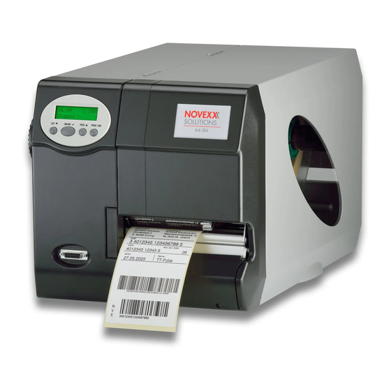
08/10 Rev. 5.05-01 TECHNICAL MANUAL Mounting the PLC 64-xx System Requirements Printer 64-xx dispenser with USI interface board installed. For details see topic section „Technical Da- ta“, chapter „System Requirements“. Applicator LTSI / LTP / LTPV PLC module Component Part number Picture PLC module for C0823 (LH) -
Page 3: Assembly
08/10 Rev. 5.05-01 TECHNICAL MANUAL Mounting the PLC 64-xx Assembly Safety WARNING! This unit operates at mains voltage! Coming into contact with electrically live components can cause potentially lethal electrical shocks and burns. Only authorised technicians are permitted to remove any parts of the enclosure. -
Page 4: Required Tools
08/10 Rev. 5.05-01 TECHNICAL MANUAL Mounting the PLC 64-xx Required Tools • Philips screwdriver sizes 1 and 3 • Screwdriver of medium size • Hex socket wrench WAF 4.5 • Allen key 3 mm with ball head • Flat nose pliers Fitting the Cable Harness 1. - Page 5 08/10 Rev. 5.05-01 TECHNICAL MANUAL Mounting the PLC 64-xx 4. Remove the cable clamp (1) from the prin- ter bottom (by means of a screwdriver). Fig. 4 shows the two fixing holes (2) to which the PLC module is screwed. The frontal hole was beforehand used to fix the power supply.
- Page 6 08/10 Rev. 5.05-01 TECHNICAL MANUAL Mounting the PLC 64-xx 8. Right now is the best moment to connect the PLC module to the USI board! See paragraph Connecting the PLC for LTP/LTPV operation on page 7 respective- ly paragraph Connecting the PLC for LTSI operation on page 8.
-
Page 7: Connecting The Plc For Ltp/Ltpv Operation
08/10 Rev. 5.05-01 TECHNICAL MANUAL Mounting the PLC 64-xx Connecting the PLC for LTP/ LTPV operation Also refer to section Connection Diagram 64-xx on page 10. The cable harness fitted earlier consists of three cables, labeled VENT, SENS and MOTOR. Two connectors on the PLC board are also labeled VENT and SENS (see figs. -
Page 8: Connecting The Plc For Ltsi Operation
08/10 Rev. 5.05-01 TECHNICAL MANUAL Mounting the PLC 64-xx Connecting the PLC for LTSI operation Also refer to section Connection Diagram 64-xx on page 10. The cable harness fitted earlier consists of three cables, labeled VENT, SENS and MOTOR (fig. 1). Two connectors on the PLC board are also labeled VENT and SENS. - Page 9 08/10 Rev. 5.05-01 TECHNICAL MANUAL Mounting the PLC 64-xx 3. Connect the plugs (1) and (2) to the USI board (fig. 4). Plug the plug (1) exactly into the position shown! When plugging in plug (2), pay attention to the information on the cable sleeve! 4.
-
Page 10: Appendix
08/10 Rev. 5.05-01 TECHNICAL MANUAL Mounting the PLC 64-xx Appendix Connection Diagram 64-xx LTP/LTPV USI board Mind the connection note on the cable sleeve! Applicator USI2 connector USI1 SENS VENT MOTOR Cable harness Connection board Notto be connected! Fig. 1: Correct connection of the PLC for LTP/LTPV to an 64-xx. - Page 11 08/10 Rev. 5.05-01 TECHNICAL MANUAL Mounting the PLC 64-xx LTSI USI board Jumper: On = 400mm-Applicator Mind the connection Off = 200mm-Applicator note on the cable sleeve!! Applicator USI2 connector USI1 SENS Motor D-Sub cable harness output VENT stage Connection power supply C0896 MOTOR...
-
Page 12: Signal-Leds At The Plc
08/10 Rev. 5.05-01 TECHNICAL MANUAL Mounting the PLC 64-xx Signal-LEDs at the PLC PLC status LEDs Input X0-X7 Operation mode switch Output Y0-Y7 Fig. 3: Control elements at the PLC. Operation mode Must be set to RUN for normal operation. switch PLC status Meaning... - Page 13 08/10 Rev. 5.05-01 TECHNICAL MANUAL Mounting the PLC 64-xx Input assignment: LTSI / LTP / LTPV Touchdown sensor: On = No touchdown signal Home position sensor: On = Applicator is not in home position Product sensor: On = Product detected Print_End signal coming from USI: On = Printing / feeding is active Error signal coming from USI...
- Page 14 08/10 Rev. 5.05-01 TECHNICAL MANUAL Mounting the PLC 64-xx LTSI LTP / LTPV Y2 Motor direction: Vacuum valve: On = Down movement On = Vacuum switched on (from feed start until appli- cation) Y3 Error signal to the 15-pin output connector at the USI (ana- logous to the USI description) Y4 Start_Print signal to the USI: On = Label printing is enabled...
Need help?
Do you have a question about the 64 Series and is the answer not in the manual?
Questions and answers