Table of Contents
Advertisement
Advertisement
Table of Contents

Related Manuals for Daikin iTM plus


Summary of Contents for Daikin iTM plus
- Page 1 Installation Manual iTM plus adaptor Model DCM601A72...
- Page 2 Disclosure To the User in USA Part 15 of FCC Note: This equipment has been tested and found to comply with the limits for a Class B digital device, pursuant to part 15 of the FCC Rules. These limits are designed to provide reasonable protection against harmful interference in a residential installation.
- Page 3 WARNING • Only qualified personnel must carry out the installation work. • Consult your Daikin dealer regarding relocation and reinstallation of the con- troller. Improper installation work may result in electric shocks or fire. • Install the controller in accordance with the instructions in the installation man- ual.
- Page 4 • Install the control wires for the controller at least 3.5 feet (1 meter) away from televisions or radios to prevent image interference or noise. Depending on the radio waves, a distance of 3.5 feet (1 meter) may not be sufficient to eliminate the noise. Installation Manual 3P291714-4B English DCM601A72 iTM plus adaptor...
-
Page 5: Table Of Contents
Connecting power supply ......................20 2.4.1 Terminal location and schematic wiring diagram ............20 2.4.2 Wiring specifications ...................... 21 Secure installation of iTM plus adaptor .............. 22 Screw mounting to control enclosure ..................22 3.1.1 Installation procedure ....................22 DIN rail mounting ........................23 3.2.1 Removal from DIN rail .................... - Page 6 Quick Operation Guide ..................30 Viewing target area and management point information in list format ........30 Displaying areas and management points ................30 Starting/stopping an area or management point ..............31 Installation Manual 3P291714-4B English DCM601A72 iTM plus adaptor...
-
Page 7: Before Installation
• Check that the iTM plus adaptor comes with all accessories. • Understand where the terminals and switches of the iTM plus adaptor are located. • Make sure that an appropriate space for installing the iTM plus adaptor is available. Checking that all accessories are included Based on the following accessory list, check that all accessories for the iTM plus adaptor are included. -
Page 8: Understanding External Dimensions
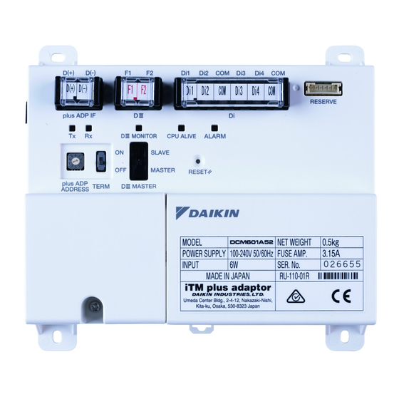
“2. Electric wiring”. 1.3.1 Front face All the terminals used during installation are located on the front face of the iTM plus adaptor. The power supply terminal is protected with a cover for safety. Remove the screw to detach the cover. - Page 9 [plus ADP ADDRESS] The switch for selecting the address of the iTM plus adaptor. For each iTM plus adaptor, set a unique number between 2 to 8.
-
Page 10: Determining Installation Place
Touch Manager and iTM Blink plus adaptor Determining installation place Be sure to install the iTM plus adaptor in a place that meets the conditions described in 1.4.1 to 1.4.3. 1.4.1 Installation place and mounting direction Below are the description of the installation place and mounting direction. Be sure to confirm. -
Page 11: Required Space
• Make sure that there is a minimum clearance of 25/32 in. between each unit and wiring ducts. • Multiple iTM plus adaptors can be installed without clearance in the horizontal direction. <Installation space required for iTM plus adaptor> Required installa-... -
Page 12: Electric Wiring
This chapter describes the procedure for connecting the iTM plus adaptor with intelligent Touch Manager, DIII-NET-compatible air conditioning devices and other equipment. In addition to air conditioners, the iTM plus adaptor can be connected and work with a wide range of equipment. However, the required connection procedures vary depending on the equipment to be connected. -
Page 13: Connecting Intelligent Touch Manager
2.1.1 Terminal location and schematic wiring diagram Connect the plus ADP IF terminal of the iTM plus adaptor to the plus ADP IF terminal on the rear face of the intelligent Touch Manager. Note that these terminals have polarity. Be sure to connect the positive wire to the “+”... -
Page 14: Address Setup And Termination Resistor
Touch Manager is always set to "1". Therefore, the setting range for the iTM plus adaptor is from “2” to “8”. Use the plus ADP ADDRESS switch on the front face of the iTM plus adaptor to set the address. -
Page 15: Connecting Diii-Net-Compatible Air Conditioning Equipment
The iTM plus adaptor allows you to connect additional 64 groups of air conditioners per unit. Considering that the intelligent Touch Manager can be connected with a maximum of seven iTM plus adaptors, you can control a total of 512 groups of air conditioners at a maximum using a single intelligent Touch Manager. -
Page 16: Terminal Location And Schematic Wiring Diagram
Make sure that the wires you are connecting to the F1 and F2 terminals are not power wires. Inadvertently connecting power wires to these terminals results in a failure of the air conditioner or iTM plus adaptor. <Schematic diagram of wiring between air conditioning equipment>... -
Page 17: Wiring Specifications
MASTER and SLAVE relationship for those controllers. Assign only one of those controllers to MASTER, and other controllers to SLAVE. The iTM plus adaptor is set to MASTER by default. Change the setting to SLAVE in any of the following cases: •... -
Page 18: Connecting An Emergency Stop Input Device Or Power Meter
• Wiring Adaptor for Electrical Appendices (1) (KRP2) Connecting an emergency stop input device or power meter The iTM plus adaptor can perform operations such as an emergency stop of air condition- ers according to the external signal input device, and an electricity usage calculation for each air conditioner (for power proportional distribution) according to the pulse inputs from a power meter. -
Page 19: Terminal Location And Schematic Wiring Diagram
2.3.1 Terminal location and schematic wiring diagram Use the terminal with the “Di” mark to connect the pulse signal line. The iTM plus adaptor accepts four types of signals through its four channel terminals, Di1, Di2, Di3, and Di4, and two COM terminals (ground). -
Page 20: Connecting Power Supply
Connecting power supply Connect the iTM plus adaptor to an power supply. WARNING Be sure to perform the operation during power-off conditions. Do not turn on the power supply before all wire connections are completed. Not doing so may cause an electric shock. -
Page 21: Wiring Specifications
• The power supply requires earth leakage breaker installation and earth wire connection. • After installing an earth leakage breaker, be sure to connect only the iTM plus adaptor to it. • To prevent accidents due to wire breakage or disconnection, secure the power supply cables to the blue resin cable mount with cable ties. -
Page 22: Secure Installation Of Itm Plus Adaptor
Screw mounting to control enclosure 3.1.1 Installation procedure Secure the iTM plus adaptor to the control enclosure using the supplied round-head wood screws. When done, remove the blue protective film from the upper portion of the unit body. <Mounting to control enclosure>... -
Page 23: Din Rail Mounting
Do not use screws to secure the iTM plus adaptor onto the DIN rail. Place the iTM plus adaptor over the top of the DIN rail so that the upper hook (1) on the rear face is hooked and push it in direction (3) until the lower hook (2) snaps into the DIN rail. -
Page 24: Removal From Din Rail
3.2.1 Removal from DIN rail Pull down the lever at the lower portion of the iTM plus adaptor (1) and pull the unit body (2) out toward you. Installation Manual 3P291714-4B English DCM601A72 iTM plus adaptor... -
Page 25: Setting Diii-Net Address For Each Air Conditioner
CAUTION • Make sure that the iTM plus adaptor is connected to the intelligent Touch Man- ager and that both units are powered on. You cannot perform address settings for air conditioners without turning on the power supply. -
Page 26: Setting Address With Wired Remote Controller
GROUP SETTING NOTE If the power is not supplied for the intelligent Touch Manager or iTM plus adaptor, you cannot change the value to “ ”. Turn on the power supply for both the intelligent Touch Manager and iTM plus adaptor, and wait for a while before starting the operation. - Page 27 The DIII-NET address has been set. <Step 5> GROUP SETTING 6. Press the Inspection/Test Operation button. You are now brought back to the screen shown in Step 6-2. <Step 6-1> GROUP SETTING <Step 6-2> English Installation Manual 3P291714-4B DCM601A72 iTM plus adaptor...
-
Page 28: Setting Address With Navigation Remote Controller
Forced Fan ON Setting NOTE If the power is not supplied for the iTM plus adaptor, the “Group Address” menu is not displayed. Turn on the power supply for the intelligent Touch Manager and wait for a while before starting the operation. -
Page 29: Setting An Unique Address To Each Unit (When Power Proportional Distribution (Option) Is Used)
When power distribution is enabled, you need to set a unique address for each unit. For how to set an address, refer to the Commissioning Manual Supplementary Volume Power Proportional Distribution (EM11A027). English Installation Manual 3P291714-4B DCM601A72 iTM plus adaptor... - Page 30 Touch the Down button to go to the area being selected and view the areas and management points in it. Touch the Up button to go to the area one level above the current area. Installation Manual 3P291714-4B English DCM601A72 iTM plus adaptor...
- Page 31 Select Start or Stop in the On/Off buttons. When operation is started, the icon color changes to green or red (depending on the system setting). When operation is stopped, the color changes to grey. English Installation Manual 3P291714-4B DCM601A72 iTM plus adaptor...
- Page 32 3P291714-4B EM11A030A (1306) HT...
Need help?
Do you have a question about the iTM plus and is the answer not in the manual?
Questions and answers