Furuno TZT16F Installation Manual
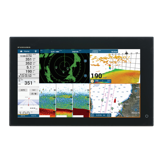
Multi function display
Hide thumbs
Also See for TZT16F:
- Operator's manual (17 pages) ,
- Operator's manual (17 pages) ,
- Installation manual (74 pages)
Table of Contents
Advertisement
Quick Links
Installation Manual
MULTI FUNCTION DISPLAY
TZT16F
Model
SAFETY INSTRUCTIONS ................................................................................................ i
SYSTEM CONFIGURATION ........................................................................................... ii
EQUIPMENT LISTS........................................................................................................ iii
1. MOUNTING..............................................................................................................1-1
1.1 Installation of Multi Function Display..................................................................................1-1
1.2 Installation of Transducers.................................................................................................1-6
2. WIRING....................................................................................................................2-1
2.1 Interface Connections (Rear of Unit) .................................................................................2-1
2.2 Composite Connector ........................................................................................................2-2
2.3 How to Secure and Waterproof Connections.....................................................................2-3
2.4 Power Cable ......................................................................................................................2-3
2.5 MULTI Cable......................................................................................................................2-4
2.6 DRS Radar Sensor Connections .......................................................................................2-5
2.7 Network Connector ............................................................................................................2-5
2.8 CAN bus (NMEA2000 Connector) .....................................................................................2-5
2.9 Transducer (Option)...........................................................................................................2-9
2.10 Example TZT16F System Configurations ........................................................................2-10
3. HOW TO SET UP THE EQUIPMENT......................................................................3-1
3.1 How to Set Time Zone, Time Format and Language.........................................................3-3
3.2 How to Set Units of Measurement .....................................................................................3-4
3.3 Initial Setup ........................................................................................................................3-5
3.4 How to Set Up the Radar .................................................................................................3-11
3.5 How to Set Up the Sounder .............................................................................................3-13
3.6 Wireless LAN Setting .......................................................................................................3-18
3.7 Ferry Mode.......................................................................................................................3-20
PACKING LISTS ......................................................................................................... A-1
OUTLINE DRAWINGS ................................................................................................ D-1
INTERCONNECTION DIAGRAMS.............................................................................. S-1
www.furuno.com
All brand and product names are trademarks, registered trademarks or service marks of their respective holders.
Advertisement
Table of Contents

Related Manuals for Furuno TZT16F


Summary of Contents for Furuno TZT16F
-
Page 1: Table Of Contents
2.7 Network Connector ......................2-5 2.8 CAN bus (NMEA2000 Connector) ..................2-5 2.9 Transducer (Option)......................2-9 2.10 Example TZT16F System Configurations ................2-10 3. HOW TO SET UP THE EQUIPMENT..............3-1 3.1 How to Set Time Zone, Time Format and Language............3-3 3.2 How to Set Units of Measurement ..................3-4 3.3 Initial Setup ........................3-5... - Page 2 The paper used in this manual is elemental chlorine free. ・FURUNO Authorized Distributor/Dealer 9-52 Ashihara-cho, Nishinomiya, 662-8580, JAPAN A : FEB 2020 Printed in Japan All rights reserved. Pub. No. IME-45110-A (TEHI ) TZT16F 0 0 0 1 9 7 1 0 7 1 0...
-
Page 3: Safety Instructions
If your vessel is configured with 0.70 m 0.45 m TZT16F an autopilot system, install an autopilot control unit (or emer- gency autopilot stop button) at each helm station, to allow you to disable the autopilot in an emergency. -
Page 4: System Configuration
The basic functions of the hub were verified, however the compatibility of all functions were not checked. FURUNO cannot guarantee proper operation. : When using a USB OTG as a USB host device, this equipment operates as a touch operation output device. -
Page 5: Equipment Lists
EQUIPMENT LISTS Standard supply Name Type Code No. Remarks Multi Function Display TZT16F Installation Materials CP19-02500 000-037-168 Accessories FP26-00401 001-175-940 Optional supply Name Type Code No. Remarks Bracket OP19-21 001-563-940 For hanger installations. Retrofit Kit OP19-23 001-563-980 For retrofit installations. - Page 6 EQUIPMENT LISTS Name Type Code No. Remarks Cable Assy. FRU-F12F12-100C 001-560-390 FRU-F12F12-200C 001-560-400 FRU-F7F7-100C 001-560-420 FRU-F7F7-200C 001-560-430 Fish Finder Power DI-FFAMP 000-037-175 For 2 to 3 kW Dual-frequen- Amplifier cy CHIRP transducers Transducer 000-015-204 600 W 520-5PSD* (for internal fish finder) 000-015-212 520-5MSD* 000-146-966...
- Page 7 EQUIPMENT LISTS Name Type Code No. Remarks CHIRP Transducer TM150M 000-035-500 300 W (for internal fish finder) B-75L 000-035-501 B-75H 000-035-502 600 W B-175H 000-035-504 1 kW B-175L 000-035-503 CHIRP Transducer B265LH-FJ12 000-037-609 1 kW (for internal fish finder) CM265LH-FJ12 000-037-610 ACCU-FISH function...
- Page 8 EQUIPMENT LISTS Dual Frequency CHIRP (For internal fish finder) Output power Model Remarks B265LH CM265LH TM265LH ACCU-FISH function available 1 kW B265LM B275LHW CM265LM ACCU-FISH function NOT available CM275LHW TM265LM TM275LHW Dual Frequency CHIRP (For DI-FFAMP) Output power Model 2 kW PM111LH PM111LHW R109LH...
-
Page 9: Mounting
MOUNTING Installation of Multi Function Display The TZT16F is designed to be mounted in a console or panel, or mounted on a desk- top. The installer of this equipment must read and follow the descriptions in this manual. Wrong installation or maintenance can void the warranty. - Page 10 A tool can be used to fasten the wing nuts; use caution so as not to damage the wings or thread. 3. Connect all cables at the back of the TZT16F. (See section 2.1) 4. Remove the hex bolts from the flush mounting plate.
- Page 11 1. MOUNTING 7. Attach the flush mount fixture to the TZT16F with hex bolts. ② ② Set TZT16F to the cutout. Attach the flush mounting Attach the flush mounting ① ① plate to the TZT16F. plate to the TZT16F. 8. Fasten each wing bolt (4 pcs.) so that the protector for screw touches the mount- ing panel.
- Page 12 TZT16F. 2. Place the TZT16F unit face-down on a a soft, clean surface. 3. Set the F Mount Panel to the TZT16F unit, then using the hex bolts attached to TZT16F, fix the F Mount Panel to the unit. TZT unit...
- Page 13 1.1.3 Desktop mounting (option) Follow the appropriate procedure below to mount the TZT16F. Use the optional kit Bracket16 (contents shown below), for mounting the TZT16F. Type: OP19-21 Code No. 001-563-940 Name Type Code No.
-
Page 14: Installation Of Transducers
1. MOUNTING 2. Place the TZT16F face-down on a soft, clean surface, then fit the washers and knob bolts as shown in the figure below, leaving a gap of approximately 30 mm. The washers have a leading edge which must face the unit. - Page 15 1. MOUNTING There are three methods for installing the ø22 ø24 transducer on the ship (thru-hull mount, in- side the hull and transom mount) and one of those methods is to be selected according to the structure of the ship. The procedure which follows below shows how to install a small transducer (520-5PSD/5MSD) as the representative example of installation.
- Page 16 1. MOUNTING Installation procedure 1. With the boat hauled out of the water, mark the location chosen for mounting the transducer on the bottom of the hull. 2. If the hull is not level within 15° in any direction, fairing blocks made out of teak should be used between the transducer and hull, both inside and outside, to keep the transducer face parallel with the water line.
- Page 17 1. MOUNTING 1.2.2 How to mount a transducer inside the hull NOTICE This installation method affects the ability to detect the bottom, fish and other objects because the ultrasound pulse is weakened when it passes through the hull. Therefore, refrain from this mounting method for a transducer that supports the RezBoost™...
- Page 18 7. Confirm the available fish finder from the list of available sounders, then tap the appropriate fish finder. For the purpose of this example, the default setting [TZT16F] (internal sounder) is selected as the source. 8. Tap the [<] icon to return to the [Fish Finder] menu.
- Page 19 1. MOUNTING Installation procedure 1. Lightly roughen the transducer face with #100 sandpaper. Also, use the sandpa- per to roughen the inside of the hull where the transducer is to be mounted. Wipe off any sandpaper dust from the face of the transducer. 2.
- Page 20 1. MOUNTING 1.2.3 How to install the transom mount transducer The optional transom mount transducer is very commonly employed, usually on relatively small I/O or outboard boats. Do not use this method on an inboard motor boat because turbulence is created by the propeller ahead of the transducer. DO NOT over-tighten screws, to prevent damage to the transducer.
- Page 21 1. MOUNTING Transducer preparation Before putting your boat in water, wipe the face of the transducer thoroughly with a liquid detergent. This will lessen the time necessary for the transducer to have good contact with the water. Otherwise the time required for complete "saturation" will be lengthened and performance will be reduced.
- Page 22 1. MOUNTING 525STID-PWD The optional triducer 525STID-PWD is designed for transom mounting. However, select the location where influ- Height without ences from bubbles and turbulences are speed sensor minimal to ensure the best performance. 191 mm (7-1/2") Allow adequate space above the bracket Height with Height Height...
- Page 23 1. MOUNTING 4. If you know your transom angle, the bracket is designed for a standard 13° transom angle. 11°-18° angle: No shim is required. Skip to step 3 in "Adjustments". Other angles: The shim is required. Skip to step 2 of "Adjustments". If you do not know the transom angle, temporarily attach the bracket and sensor to the transom to determine if the plastic shim is needed.
- Page 24 1. MOUNTING 5. Using the vertical adjustment space on the bracket slots, slide the sensor up or down to provide a projection of 3 mm Cable cover (1/8”). Tighten the screws. Cable clamp 50 mm (2") Hull projection 3 mm (1/8") How to attach the sensor to the bracket 1.
- Page 25 1. MOUNTING 3. If a hole has been drilled in the transom, open the appropriate slot in the transom cable cover. Position the cover over the cable where it enters the hull. Mark the two mounting holes. 4. At each of the marked locations, use a 3 mm or 1/8” bit to drill a hole 10 mm (3/8”) deep.
- Page 26 1. MOUNTING This page is intentionally left blank. 1-18...
-
Page 27: Wiring
WIRING Interface Connections (Rear of Unit) Rear of TZT16F Rear of TZT16F 12-10P Conversion Cable Ground wire FRU-CCB12-MJ-01 (Local supply, (0.4m, supplied) IV-8sq.)* Core Power Cable TO: Ship’s ground FRU-3P-FF-A002M- 001 2 m, supplied) TO: 12 to 24 VDC Transducer Cable... -
Page 28: Composite Connector
You can connect to external devices such as buzzers and event switches. Refer to section 2.5 for details. USB port The TZT16F has two USB Ver. 2.0 ports which can be used to connect an optional SD card unit or remote control unit, and to control a touch monitor. -
Page 29: How To Secure And Waterproof Connections
How to Secure and Waterproof Connections Where the unit is exposed to water spray or moisture, all the connectors and Multi ca- ble connections to the TZT16F must have at least IPx6 waterproof rating. All unused cable ends should be covered for protection. -
Page 30: Multi Cable
2. WIRING MULTI Cable Use the MULTI cable for the NMEA0183 equipment, external buzzer to supply power to the CAN bus. The connector has 9 wires and connector (SMP-11V). Use the table below for reference and connector (SMD-11V, local supply) when connecting the MULTI cable. -
Page 31: Drs Radar Sensor Connections
TZT16F Network Connector Like previous NavNet series equipment, the TZT16F may share Radar and Fish Find- er images, and other information, across a Ethernet connection. Up to six TZT16F units may be connected to the same network at one time. However, for configurations with one or more TZT2BB included, the maximum number of networked TZT16F units is four. - Page 32 , the TZT16F can display engine information on a dedicated Yamaha engine status display. How to connect the engine The TZT16F connects to the Yamaha engine network via the Yamaha Interface Unit. Arrange the Yamaha Interface Unit through a local Yamaha representative. Yamaha Interface Unit...
- Page 33 /Command Link Plus /Helm Master How to set up the engine display Once the TZT16F detects the Yamaha engine network, the engine can be set up on [Settings][Initial Setup][YAMAHA ENGINE SETUP]. See section 3.3 for details. 2.8.3 NMEA0183 equipment data input Note: To output NMEA0183 data, see paragraph 2.5.1.
- Page 34 The CAN bus output PGN setting (found under the [Initial Setup] menu) is global to the network. Note that only one TZT16F will output CAN bus data on the network at a time: the TZT16F which is powered ON first. If that display is turned OFF, another will take its place to output the data.
-
Page 35: Transducer (Option)
Transducer (Option) The 12-10P conversion cable (FRU-CCB12-MJ-01, 0.4m, supplied) is required when connecting a transducer that has a 10-pin connector to TZT16F. Matching Box MB- 1100 is also required when connect 1kW transducer to TZT16F. See the interconnec- tion diagram for transducer connection. The transducer that has a 12-pin connector... -
Page 36: Example Tzt16F System Configurations
300W/600W/1kW 2/3kW Transducer (Selectable) Note 1: Matching Box MB-1100 (optional supply) is required for some FURUNO trans- ducers. See the INTERCONNECTION DIAGRAM at the back of this manual. Note 2: Conversion cable FRU-CCN12-MJ-01 (supplied) is required for some trans- ducers. - Page 37 CAN bus backbone cable CAN bus CAN bus drop cable HUB-101* drop cable Multi Function Display Multi Function Display Multi Function Display Multi Function Display TZT16F TZT16F TZT16F TZT16F USB Hub* Conversion 12 to 24 12 to 24 VDC 12 to cable...
- Page 38 2. WIRING This page is intentionally left blank. 2-12...
-
Page 39: How To Set Up The Equipment
HOW TO SET UP THE EQUIPMENT This chapter shows you how to set up your system according to the equipment you have connected. Touch control description The touch control depends on the screen type. The basic operations to use during the installation setup are in the following table. - Page 40 3. HOW TO SET UP THE EQUIPMENT 5. Drag the menu to show [Initial Setup], then tap [Initial Setup]. Back icon Menu title Close icon Preview screen Preview screen Changes made in the Changes made in the Menu Menu menu can be menu can be items items...
-
Page 41: How To Set Time Zone, Time Format And Language
3. HOW TO SET UP THE EQUIPMENT How to Set Time Zone, Time Format and Lan- guage Before setting up your equipment, select the time zone, language and units to use on your equipment as shown below. 1. Tap the [Home] icon to show the home screen and display mode settings. 2. -
Page 42: How To Set Units Of Measurement
3. HOW TO SET UP THE EQUIPMENT How to Set Units of Measurement 1. Tap the [Home] icon to show the home screen and display mode settings. 2. Tap [Settings] to show the [Settings] menu. 3. Drag the main menu to display [Units], then tap [Units]. 4. -
Page 43: Initial Setup
3. HOW TO SET UP THE EQUIPMENT Initial Setup This section shows you how to set your system according to the sensors you have connected. Note: Some units are set to metric in this section, actual setting ranges vary depending on the unit of measurement set in the [Units] menu. 1. - Page 44 3. HOW TO SET UP THE EQUIPMENT Manual Fuel Management Setup Menu item Description Options (setting range) [Total Fuel Capacity] Enter the total fuel capacity of your 0 to 9,999(L). tank(s). [Manual Fuel Manage- Set to [ON] for manual fuel manage- [OFF], [ON].
- Page 45 Select the source for each data to input to the system. If two or more sources are connected for a data, select one using the pull-down dialog box. The FURUNO products are shown at the upper part of the list. [Sensor List] Show the information for sensors connected to your equipment.
- Page 46 The system ID for this device within the network. [IP Address] IP address for this unit within the network. [Quick Self Test] Displays various details regarding the TZT16F unit, radar and fish finder. [Certification Mark] Displays relevant certification for this equipment. [Service] Requires login password.
- Page 47 004/MCU-005 connection. Further, the cycling order of displays can be set. See the Operator’s Manual. [Sirius Radio Diag- Check the satellite radio of the FURUNO BBWX SiriusXM weather receiver nostic] for proper operation. See the Operator’s Manual. [Sirius Weather Diag-...
- Page 48 [OK], [Cancel] tings] [Initial Setup] menu - [Engine & Tank Automatic Setup] The TZT16F will automatically detect engines and tanks connected to the same net- work. This is the recommended method for setting up engines and tanks. [Initial Setup] menu - [Engine & Tank Manual Setup] The manual set up method should only be used if the automatic setup did not correctly detect your engines or tanks.
-
Page 49: How To Set Up The Radar
3. HOW TO SET UP THE EQUIPMENT How to Set Up the Radar 1. Tap the [Home] icon to show the home screen and display mode settings. 2. Tap [Radar] from the [Settings] menu. 3. Tap [Radar Source], then select the appropriate radar sensor. Note: If a DRS sensor is connected but does not appear in the [Radar Source] list, close the list and open it again. - Page 50 3. HOW TO SET UP THE EQUIPMENT Menu item Description Options (setting range) [Tuning Source] Select a display in the dual range display to [Range1], [Range2] manually tune. Not available (greyed out) with the radar sensor DRS4D-NXT, DRS4DL, DRS4DL+. [Manual Tuning] Manually tune the radar.
-
Page 51: How To Set Up The Sounder
3. HOW TO SET UP THE EQUIPMENT How to align the antenna heading You have mounted the antenna unit facing straight ahead in the direction of the bow. Therefore, a small but conspicuous target dead ahead visually should appear on the heading line (zero degrees). - Page 52 Select [ON] if you use this equipment in salt water. [ON], [OFF] [Fish Finder Select the sounder used. [TZT16F], [DFF1/ Source] Note: Where the TZT16F’s nickname has been changed BBDS1], [DFF3], in [INITIAL SETUP] [SENSOR LIST], the [Fish Finder [DFF1-UHD] Source] option reflects the name change. [Preset Frequency...
- Page 53 3. HOW TO SET UP THE EQUIPMENT Options (setting Menu item Description range) [Bottom Level HF] The default bottom level setting (0) determines that two [-40] to [40] strong echoes received in sequence are bottom echoes. If [Bottom Level LF] the depth indication is not stable in the default setting, adjust the bottom level here.
- Page 54 Note 3: When the DI-FFAMP is connected and [Transducer Setup Type] menu is set to [Manual], the message “Power amplifier unit detected: In order to manually adjust your transducer setup, please contact your Furuno dealer.” appears. Contact your FURUNO dealer for setup.
- Page 55 3. HOW TO SET UP THE EQUIPMENT Options Menu item Description (setting range) [Low Frequency Max] Display the low frequency maximum.* [Reset Default Set- Reset the Transducer Setup menu settings to default. [OK], [Cancel] tings] *: This item is only available for DFF3 users. When [Transducer Setup Type] is set to [Model] and connected to DFF3 Options Menu item...
-
Page 56: Wireless Lan Setting
Bow/Stern for LF Options Menu item Description (setting range) [Motion Sensor Select the sensor connected to your TZT16F unit. For all [SC30], Type] sensors other than SC-50 and SC-110, select [SC-30]. [SC50_SC110] Note: This menu item is not available when [Fish Finder Source] is set to [TZT16F]. - Page 57 How to create a wireless LAN network Smart devices connected to this wireless network may also connect directly to the unit, allowing use of the TZT16F applications. 1. Tap the Home icon ( ) to show the home screen and display mode set- tings.
-
Page 58: Ferry Mode
Ferry mode allows the user to change the screen orientation by 180°. Note that all the above heading sensors must support heading offset command from the TZT16F. Both heading sensors and radar sensors must be powered on when the TZT16F sends the command. Both the heading sensor and radar sensor must be powered when the TZT16F sends the heading offset command to them. - Page 65 11/Nov/2019 H.MAKI...
Need help?
Do you have a question about the TZT16F and is the answer not in the manual?
Questions and answers