
Related Manuals for Test Equipment Depot CW240


Summary of Contents for Test Equipment Depot CW240
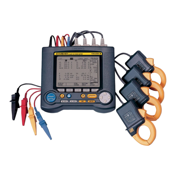
- Page 1 99 Washington Street Melrose, MA 02176 Fax 781-665-0780 TestEquipmentDepot.com User's CW240 Clamp-on Power Meter Manual Quick Setup Manual IM CW240P-E IM CW240P-E 1st Edition: Jul 2004 (KP)
-
Page 2: Table Of Contents
Index Introduction ..................1 Precautions for Safe Use of the CW240 ........2 1. Part Names and How to Use Parts ......1-1 Part Names and How to Use Parts ........1-1 Screen Configuration ............1-2 Operation Keys ..............1-8 2. Preparation for Measurements ........ 2-1 Connecting a Power Supply .......... -
Page 3: Introduction
Thank you for purchasing our CW240 Clamp-on Power Meter. This Quick Setup Manual briefly describes the key operations as well as setting examples of the CW240 upon actual measurement, so that you can operate the CW240 for the first time. -
Page 4: Precautions For Safe Use Of The Cw240
Precautions for Safe Use of the CW240 The following safety symbols are used on the CW240 and in this manual. WARNING Indicates a hazard that may result in the loss of life or serious injury of the user unless the described instructions is abided by. -
Page 5: Part Names And How To Use Parts
PC card slot AC adapter jack Button for extracting a PC card Power switch Battery holder Battery holder lock switch For more details, refer to the CW240 User's Manual Chapter 2, "Part Names and How to Use Parts" IM CW240P-E... -
Page 6: Screen Configuration
U WAVEFORM, I WAVEFORM) VOLT. QUALITY WIRING DIAGRAM WIRING CHECK For more details, refer to the CW240 User's Manual Section, "2.4 Screen Configuration" IM CW240P-E Test Equipment Depot - 800.517.8431 - 99 Washington Street Melrose, MA 02176 FAX 781.665.0780 - TestEquipmentDepot.com... - Page 7 Displaying Measure Screen ● How to Display Measure Screen Press the TOP MENU key. MENU Using the cursor key, select the MEASURE icon (highlighted). Press the ENTER key to display the Measure screen. ENTER (The List screen is used as an example.) IM CW240P-E...
- Page 8 • VT ratio • Current range • I4 (1P3W31, 3P4W4I) • CT ratio Function key labels • Sampling method • Frequency source/fixed clock • Interval time For more details, refer to the CW240 User's Manual Section 7.2.2, "Description of Display" IM CW240P-E...
- Page 9 Displaying Setup Screen ● How to Display Setup Screen Press the TOP MENU key. The Top Menu screen appears. MENU Using the cursor key, select the SETUP icon (highlighted). Press the ENTER key to display the top Setup screen. ENTER Using the cursor key, select VARIOUS SETUP (highlighted).
- Page 10 ● Description of Display Tab: Use the cursor key to select a tab. These show that the right and left direction cursor key is active. Cursor key: Moves to any setting items. Function keys: Use these keys to make each setting. These show that up and down direction cursor key is active, and appear only if there are two or more tab setting pages.
- Page 11 Appears if the amount of data exceeds the capacity of a PC card or the internal memory. Appears when the CW240 is configured so that data is saved in a PC card. Also, this mark blinks during an access to the PC card.
-
Page 12: Operation Keys
Copy destination setting: PC card, internal memory, or printer For more details, refer to the CW240 User's Manual Section 2.2, "Operation Keys" IM CW240P-E Test Equipment Depot - 800.517.8431 - 99 Washington Street Melrose, MA 02176 FAX 781.665.0780 - TestEquipmentDepot.com... -
Page 13: Preparation For Measurements
As backup power supply during a power failure, one of the following batteries can be used. Use it together with the AC adapter. • Alkaline batteries (supplied) • NiMH battery pack (optional) For more details, refer to the CW240 User's Manual Section 3.2, "Connecting a Power Supply" IM CW240P-E... -
Page 14: Connecting Voltage Probes And Current Probes
Insert the plug so that it is fastened with a voltage input terminal securely. Voltage probe, black (N terminal) Marker chips Clamp-on current probe For more details, refer to the CW240 User's Manual Section 3.3, "Connecting Voltage Probes" Section 3.4, "Connecting Clamp-on Probes" IM CW240P-E... - Page 15 <Example of three-phase three-wire two-current> Single load of three-phase three-wire two-current (3P3W2I) <Two-power-meter method> For more details, refer to the CW240 User's Manual Section 3.5, "Connection Diagrams of Voltage Probes and Clamp-on Probes" IM CW240P-E...
-
Page 16: Inserting A Pc Card Into The Cw240
With the front surface of the card facing up (the direction the arrow is pointing), insert the PC card securely into the PC card slot on the side of the CW240. For more details, refer to the CW240 User's Manual Chapter 11, "PC Card"... -
Page 17: Turning On The Power Switch
Turning ON the Power Switch Model Name Screen When the power switch is turned ON, the CW240 displays the following startup screen for approx. 2 seconds. Message Screen This screen displays the model, version number, the presence of options, and self-check results. -
Page 18: General Settings
The General 2/2 screen is displayed. For more details, refer to the CW240 User's Manual Section 6.2, "General Settings 1/2" Section 6.3, "General Settings 2/2" IM CW240P-E Test Equipment Depot - 800.517.8431 - 99 Washington Street Melrose, MA 02176 FAX 781.665.0780 - TestEquipmentDepot.com... - Page 19 Displaying General 1/2 Screen Using the right and left direction cursor key, select the General tab (highlighted). Wiring Press the F1 key (CHANGE). The window for selecting wiring appears. 3P3W+1P3W 3P4W4I 3P4W Using the cursor key, select a 3P3W3I desired wiring (highlighted). 3P3W2I 1P3W3I 1P3W...
- Page 20 Displaying General 2/2 Screen After settings of General 1/2 has been completed, display the General 2/2 screen using the up and down direction cursor key. F1 : ON F2 : OFF F1 : PLL synchronization F2 : Fixed clock F1 : 50Hz F1 : U1 F2 : 60Hz F2 : U3...
-
Page 21: Wiring
Chapter 4 Wiring 4. Wiring Displaying Wiring Diag. screen You can carry out wiring by viewing the Wiring Diag. screen. Displays the Measure screen. MENU ENTER Press the F1 key (DISPLAY CHANGE) for window callup. Using the cursor key, select WIRING DIAG. (highlighted). Press the ENTER key to display the Wiring Diag. -
Page 22: Wiring
Wiring WARNING • When attaching voltage probes to or clamping a clamp-on current probe on the circuit under test, turn off power to the circuit under test. It is extremely dangerous to connect or disconnect a voltage probe or clamp or unclamp a clamp-on current probe without turning off the circuit under test. -
Page 23: Checking Wiring
Checking Wiring You can confirm whether wiring is properly carried out or not by viewing the Wiring Check screen. Displays the Measure screen. MENU ENTER Press the F1 key (DISPLAY CHANGE) for window callup. Using the cursor key, select the WIRING CHECK (highlighted). Press the ENTER key to display the Wiring Check screen. - Page 24 NG and vice versa. For this reason, also check for an error in the vector diagram or measured values. IM CW240P-E Test Equipment Depot - 800.517.8431 - 99 Washington Street Melrose, MA 02176 FAX 781.665.0780 - TestEquipmentDepot.com...
-
Page 25: Measurements
Chapter 5 Measurements 5. Measurements Measuring an instantaneous value Settings Example: Measuring an instantaneous value of three-phase three-wire two-current (3P3W2I) 200-V line (50 Hz, 120-A load) using the clamp-on probe 96030 (rating: 200 A) Displays SETUP. MENU Top Menu screen ENTER General 1/2 Using the right and left direction cursor key, display the... - Page 26 Measurements Display a Measure screen. MENU ENTER List Screen Press the F1 (DISPLAY CHANGE) key to display the List screen. Using the cursor key, select LIST (highlighted). Press the ENTER key to confirm it. The List screen appears. ENTER IM CW240P-E...
- Page 27 <Description of the List screen> U1 to U3 : voltage rms values Uave : average voltage I1 to I3 : current rms values Iave : average current I4: 4 ch. current PA: phase angle f: frequency Analog input (optional) P : active power Q : reactive power S : apparent power PF : power factor...
- Page 28 Power Screen Press the F1 (DISPLAY CHANGE) key to display the Power screen. Using the cursor key, select POWER (highlighted). Press the ENTER key to confirm it. The Power screen appears. ENTER <Description of the Power screen> Q1 to Q3 : reactive power : total reactive power P1 to P3 : active power : total active power...
-
Page 29: Measuring Electric Energy (Integration Measurement)
Measuring Electric Energy (Integration Measurement) Making Settings Example: Measuring electric energy of three-phase three-wire two-current (3P3W2I) 200-V line (50 Hz, 120-A load) using the clamp-on probe 96030 (rating: 200 A) General 2/2 Setting Item Description (Setting value) Wh DISPLAY STANDARD Save 1/2 Setting Item Description (Setting value) - Page 30 <General 1/2> Decimal point position F1: The window for selecting the position of the decimal point appears. AUTO 000000 00000.0 0000.00 Using the cursor key, select the 000.000 desired position of the decimal point (highlighted). STANDARD Press the ENTER key to confirm it. IM CW240P-E...
- Page 31 <Save 1/2> F1 : MANUAL F1 : MANUAL F2 : TIME F2 : TIME F3: TIMER F3 : JUST Use the cursor key to shift the digit. F1 : + F2 : – F1 : PC CARD F2 : MEMORY F1 : PC CARD F2 : MEMORY F3 : PRINTER...
- Page 32 This changes the file name, proceeding to the Data Save screen. NOTE A file name will be automatically assigned if it has not been specified: File name: 240AMXXX (XXX: 000 to 029) IM CW240P-E Test Equipment Depot - 800.517.8431 - 99 Washington Street Melrose, MA 02176 FAX 781.665.0780 - TestEquipmentDepot.com...
- Page 33 < Save 2/2> After settings of Save 1/2 has been completed, display the Save 2/2 screen using up and down direction cursor key. Set the items to be saved to ON. (OFF if not) Use the cursor key to select items to be saved, and press the F1 key if the items are set to ON, and the F2 key if set to OFF.
- Page 34 Confirming Settings Displays the Measure screen. MENU ENTER Press the F1 key (DISPLAY CHANGE) for window callup. Using the cursor key, select INTEGRATE (highlighted). Press the ENTER key to display the Integrate screen. ENTER Press the F4 key to display the Setting Check screen. Check each item is set properly before pressing the ENTER key.
- Page 35 Wiring After the above settings have been completed, carry out wiring, referring to Chapter 4 in this manual. Integration Start Check that the Integrate screen is displayed. Press START&STOP key. Integration starts according to START the setting of the integration starting method. &STOP •...
- Page 36 <Forced end> Press START&STOP key displays the integration stop START confirmation message. &STOP Press the ENTER key to forcibly stop integration. ENTER "END" appears on the screen. "INTEG." "END" LED lights up LED lights up Integration in progress Status LED Integration stop date &...
-
Page 37: Measuring Harmonics
Measuring Harmonics Settings General 2/2 Setting Item Description (setting value) THP measure method THD-F (fundamental wave) Phase angle Fundamental wave method calculation method Harm. Graph Order ALL ORD. Displays SETUP. MENU ENTER General 1/2 Using right and left direction cursor key, display General 2/2 the General screen. - Page 38 The screen returns to the Top Menu screen. Wiring After the above settings have been completed, carry out wiring, referring to Chapter 4 in this manual. 5-14 IM CW240P-E Test Equipment Depot - 800.517.8431 - 99 Washington Street Melrose, MA 02176 FAX 781.665.0780 - TestEquipmentDepot.com...
- Page 39 Press the ENTER key to display the Harmonic window. ENTER (The List screen is used as an example.) For more details, refer to the CW240 User's Manual Chapter 6, "Configuring Settings" Section 6.5, "Save Data Settings 2/2" Chapter 7, "Making Measurements"...
- Page 40 <List> Element to be measured Using up and down direction cursor key, select the desired order. TOTAL: Total rms value * : Total harmonic F : Frequency distortion (frequency source) Switches the order display. ALL ORD. ODD ORD. Selects the display channel (element to be measured).
- Page 41 <Graph> Element to be measured Item Cursor measurement Using right and left direction cursor key, select the desired order. TOTAL : Total rms value * f : Frequency :Total harmonic distortion (frequency source) Switches the item. LEVEL/CONTENT/PA Selects the display channe (element to be measured).
-
Page 42: Displaying Waveform
This completes the settings, and return to the Top Menu screen. ENTER Wiring After the above settings have been completed, carry out wiring, referring to Chapter 4 in this manual. 5-18 IM CW240P-E Test Equipment Depot - 800.517.8431 - 99 Washington Street Melrose, MA 02176 FAX 781.665.0780 - TestEquipmentDepot.com... - Page 43 Press the ENTER key to display the Waveform window. ENTER The VOLT. & CURR. (U&I) screen is used as an example. For more details, refer to the CW240 User's Manual Chapter 6, "Configuring Settings" Subsection 6.5.4, "Waveform Data" Chapter 7, "Making Measurements"...
- Page 44 Changes the magnification of the vertical axis of current. Changes the magnification of the vertical axis of voltage. Changes the CH number to be displayed. (The CH number differs depending on setting of wiring.) <Vertical axis> • The display range of the vertical axis is determined on the basis of the measurement range set.
-
Page 45: Measuring Voltage Qualit (Voltage Fluctuation)
Measuring Voltage Quality (Voltage Fluctuation) Settings Example: Standard voltage: 100 V; Voltage swell: 120%; Voltage dip: 90%; Interruption: 10%; Hysteresis: 1% Save 1/2 Description Setting Item (Setting value) Measure Start TIME 2004/07/01 07:00 TIME Measure Stop 2004/07/03 07:00 Interval Time 5 min Data Save PC card... - Page 46 Displays the Measure screen. MENU Top Menu screen ENTER General 1/2 Using right and left direction cursor key, display the General 1/2 screen. Set up necessary items on the screen. For details, refer to Chapter 3 in this manual. General 2/2 Next, using up and down direction cursor key, display the General 2/2 screen.
- Page 47 <Save 1/2> F1: MANUAL Use the cursor key to F2: TIME shift the digit. F3: JUST F1: + F2: – F1: PC CARD F2: MEMORY F1: MANUAL F2: TIME F3: TIMER <Volt. Quality> F1: ON F2: OFF Use the cursor key to shift the digit.
- Page 48 Subsection 6.7, "Voltage Quality Settings" Chapter 7, "Making Measurements" Section 7.8, "Measuring Voltage Quality (Voltage Dip, Voltage Swell, or Instantaneous Interruption)" 5-24 IM CW240P-E Test Equipment Depot - 800.517.8431 - 99 Washington Street Melrose, MA 02176 FAX 781.665.0780 - TestEquipmentDepot.com...
- Page 49 ● Voltage Quality Measurement In this section, voltage dip, voltage swell or instantaneous interruption are measured and displayed. Input channel Date and time of I : Occurrence of an item under test occurrence Item O: End of detection Voltage (rms) Period of occurrence of the item under test Saves the data of voltage quality...
-
Page 50: Troubleshooting
Chapter 6 Troubleshooting 6. Troubleshooting This chapter describes how to handle problems that may arise with the CW240. If an error message has been displayed on the display screen, refer to Section 16.2, "Error Message Content and Actions" of the CW240 User's Manual. - Page 51 • Confirm that the capacity of the PC card has not been exceeded. • Confirm that the communication parameters of the CW240 and the controller, etc., match. Communication cannot be done • Confirm that the specifications of the cables through the RS-232 interface.
-
Page 52: Memory Capacity (For Reference)
32days 60min Internal 12min 13min 19min 8min 16min 13min 7min 1min Memory 12hours 13hours 19hours 8hours 16hours 13hours 7hours 60min 1min, 60min : Interval time For more details, refer to the CW240 User's Manual Section 8.3, "Memory (Reference)" IM CW240P-E... -
Page 53: Check Sheets
Chapter 8 Check Sheets 8. Check Sheets How to use these check sheets This Quick Setup Manual comes with check sheets so that you can accurately and effectively carry out on-site measurements and settings. Please make use of these sheets, describing necessary setting items in advance. Description on check sheets •... - Page 54 <1> 150V <2> 300V 4 Example <3> 600V <4> 1000V Voltage U range VT ratio 0001.00 VT ratio 1.00 0.01 to 9999.99 IM CW240P-E Test Equipment Depot - 800.517.8431 - 99 Washington Street Melrose, MA 02176 FAX 781.665.0780 - TestEquipmentDepot.com...
- Page 55 Site name: Prepared by: Date issued: Table 2: General 1/2 Item CW240 setting User setting A range (current range) Current input channels (CH) differ depending on the setting of the wiring and load. Setting of the current range (A range)
- Page 56 Check Sheet No. File name: Site name: Prepared by: Date issued: Table 3: Types of Clamp-on Current Probes *1 Model User setting – Current range (A range) <1> 200 mA <2> 500 mA 96036(2 A) – <3> 1 A <4> 2 A <1>...
- Page 57 File name: Site name: Prepared by: Date issued: Table 4: General 2/2 Item User setting CW240 setting VAR METHOD <1> ON <2> OFF SAMPLING METHOD <1> PLL synchronization <2> Fixed clock For fixed clock: <1> 50 Hz <2> 60 Hz...
- Page 58 Check Sheet No. File name: Site name: Prepared by: Date issued: Table 5: Save 1/2 Item User setting CW240 setting MEASURE START <1> MANUAL <2> TIME <3> JUST STOP <1> MANUAL <2> TIME <3> TIMER TIME Start date Stop date...
- Page 59 File name: Site name: Prepared by: Date issued: Table 6: Save 2/2 Item User setting CW240 setting <1> ON Saves data. Electric Energy data <2> OFF Does not save data. Demand data WAVEFORM data <1> ON Saves data. <2> OFF Does not save data.
- Page 60 <1> ON <2> OFF CONTENT <1> ON <2> OFF HARM. PA <1> ON <2> OFF TOTAL VAL <1> ON <2> OFF <1> ON <2> OFF IM CW240P-E Test Equipment Depot - 800.517.8431 - 99 Washington Street Melrose, MA 02176 FAX 781.665.0780 - TestEquipmentDepot.com...
- Page 61 Site name: Prepared by: Date issued: Table 8: Harmonic Output Order Setup Item User setting CW240 setting OUTPUT ORDER <1> Saves ALL ORD. (1st to 50th) <2> Saves ODD ORD. <3> Saves EVEN ORD. <4> Allows you to select harmonic orders individually.
- Page 62 Site name: Prepared by: Date issued: Table 10: Voltage Quality Item User setting CW240 setting VOLT. QUALITY MEAS. <1> ON Measures voltage quality. <2> OFF Does not measure voltage quality. <1> Change STANDARD VOLTAGE If selected: Select one of the following items:...
- Page 63 Sets LCD contrast (1 to 8). ID NUMBER 001 — 999 Year/Month/ Sets date and time (accurate time entry). DATE AND TIME Hour/Min/Sec 8-11 IM CW240P-E Test Equipment Depot - 800.517.8431 - 99 Washington Street Melrose, MA 02176 FAX 781.665.0780 - TestEquipmentDepot.com...