Chapters
Table of Contents

Subscribe to Our Youtube Channel
Related Manuals for Test Equipment Depot GSP-730


Summary of Contents for Test Equipment Depot GSP-730
- Page 1 99 Washington Street Melrose, MA 02176 Phone 781-665-1400 Toll Free 1-800-517-8431 Visit us at www.TestEquipmentDepot.com Spectrum Analyzer GSP-730 USER MANUAL GW Part No. 82SP-73000M01 ISO-9001 CERTIFIED MANUFACTURER...
- Page 2 This manual contains proprietary information, which is protected by copyright. All rights are reserved. No part of this manual may be photocopied, reproduced or translated to another language without prior written consent of Good Will company. The information in this manual was correct at the time of printing. However, Good Will continues to improve products and reserves the rights to change specification, equipment, and maintenance procedures at any time without notice.
-
Page 3: Table Of Contents
Save/Recall Files ........71 System Settings ........76 REMOTE CONTROL ............78 Interface Configuration ......80 Configure Remote Interface ...... 80 Command Syntax ........82 Command List .......... 85 FAQ ................104 APPENDIX ..............106 GSP-730 Default Settings ......106... - Page 4 GSP-730 User Manual GSP-730 Specifications ......108 GSP-730 Dimensions ......110 Declaration of Conformity ....... 111 INDEX ................112...
-
Page 5: Safety Instructions
SAFETY INSTRUCTIONS AFETY INSTRUCTIONS This chapter contains important safety instructions that you must follow during operation and storage. Read the following before any operation to insure your safety and to keep the instrument in the best possible condition. Safety Symbols These safety symbols may appear in this manual or on the instrument. - Page 6 GSP-730 User Manual Safety Guidelines Do not place any heavy object on the General instrument. Guideline Avoid severe impact or rough handling that CAUTION leads to damaging the instrument. Do not discharge static electricity to the instrument.
- Page 7 SAFETY INSTRUCTIONS Disconnect the power cord before cleaning. Cleaning Use a soft cloth dampened in a solution of mild detergent and water. Do not spray any liquid. Do not use chemicals containing harsh material such as benzene, toluene, xylene, and acetone. Location: Indoor, no direct sunlight, dust free, Operation ...
- Page 8 GSP-730 User Manual Power cord for the United Kingdom When using the instrument in the United Kingdom, make sure the power cord meets the following safety instructions. NOTE: This lead/appliance must only be wired by competent persons WARNING: THIS APPLIANCE MUST BE EARTHED...
-
Page 9: Getting Started
GETTING STARTED ETTING STARTED This chapter provides a brief overview of the GSP-730, the package contents, instructions for first time use and an introduction to the front panel, rear panel and GUI. GSP-730 Introduction ............8 Main Features ..................8 Package Contents .................. -
Page 10: Gsp-730 Introduction
GSP-730 User Manual GSP-730 Introduction The GSP-730 is a low-cost, basic spectrum analyzer. The GSP-730 has all the basic features of our more advanced models, but in a smaller package, designed especially for education. Main Features 150kHz~3GHz bandwidth Performance ... -
Page 11: Package Contents
GETTING STARTED Package Contents Check the contents before using the GSP-730. Opening the box Main unit Power cord x1 (region Contents dependent) (single unit) Quick Start Guide Calibration certificate User Manual CD ... -
Page 12: Appearance
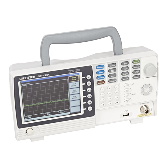
GSP-730 User Manual Appearance GSP-730 Front Panel LCD Display Function Menu keys Hardcopy key Keys GSP-730 Spectrum Analyzer Marker Preset Frequency 150 kHz 3 GHz Peak Trace Hardcopy Span Search Scroll wheel Hardcopy Display Amplitude Meas Setup System Autoset Limit Line... - Page 13 GETTING STARTED Sets the amplitude reference level, Amplitude Amplitude scale and amplitude units. Automatically searches the peak Autoset Autoset signal with maximum amplitude and displays it with appropriate horizontal and vertical scales. The Marker key is used to Marker Marker configure the markers, trace markers as well as other related functionality.
- Page 14 GSP-730 User Manual The Preset key will restore the Preset Preset spectrum analyzer to the factory settings. The hardcopy key is a quick save Hardcopy Hardcopy key that will save a screen-shot of the display. Configures the hardcopy options. Hardcopy setup...
- Page 15 GETTING STARTED RF INPUT 50 Ω RF input port. Accepts RF inputs. RF input terminal Maximum input: +30dBm (+20dBm measurable) Input impedance: 50Ω DC ±25V MAX. +30dBm MAX. Maximum DC voltage: ±25V N-type: female The numeric Numeric keypad GHz / keypad is used to...
-
Page 16: Rear Panel
GSP-730 User Manual Rear Panel USB B port RS232 port VGA port Security slot Power socket RS232 9 pin DSUB port. RS232 USB B Device port. USB 1.1/2.0 USB B VGA video-out port. Supports SVGA (480X640) Power Socket: Power Socket 100~240V, 50/60Hz. -
Page 17: Display
GETTING STARTED Display Marker information Function menu Reference level Traces and Soft menu waveforms keys Frequency/ Bandwidth settings Entry / Message area Trace icons Displays the reference level. For details, see page Reference level Displays marker information. For details see page Marker information Displays the current function menu. - Page 18 GSP-730 User Manual Displays the Start, Center and Stop frequencies, Frequency/ RBW, Span and Sweep settings. Bandwidth settings Main display showing the traces (page 62), limit Trace and waveforms lines (57) and marker positions (38).
-
Page 19: First Time Use Instructions
GETTING STARTED First Time Use Instructions Use the procedures below when first using the GSP-730 to tilt the stand, power up the instrument, update the firmware and restore the unit back to the default settings. Lastly, the Conventions sections will introduce you to the basic operating conventions used throughout the user manual. -
Page 20: Power Up And Down
Power Up into the power socket. 2. Press the power button to turn the GSP-730 on. 3. The GSP-730 will begin to boot up in under a few seconds. If system fails to start, please see your local GW Note Instek distributor. -
Page 21: Software Update
GETTING STARTED Software Update The GSP-730 allows the software to be updated Description by end-users. Before using the GSP-730, please check the GW Instek website or ask your local distributor for the latest software. The update file, MAIN1.BIN, must be placed in the root directory of a USB flash drive. -
Page 22: Usb Driver Installation
CD and install the driver. 5. To see if the driver has been successfully installed, you can check to see if the GSP-730 is recognized by the Windows Device Manager when the GSP-730 in connected to the PC. -
Page 23: Restoring Default Settings
GETTING STARTED The GSP-730 should be shown under the Ports (COM & LPT) node: If the USB driver installation fails, you can try to Note manually install the driver. You can tell that the driver hasn’t been installed if you see the AT91USBSerial icon in the ports node. -
Page 24: Conventions
The following conventions are used throughout the user manual. Read the conventions below for a basic grasp of how to operate the GSP-730 menu system and front panel keys. The F1 to F6 function keys on the right side of... - Page 25 GETTING STARTED Toggle State Pressing this menu key will toggle the state. Notice that any soft-menu key that can be toggled will have the active parameter underlined. Toggle State & Input Parameter Pressing this menu key will allow you to toggle the state of the function between on and off.
- Page 26 GSP-730 User Manual When you have navigated down a menu tree Return to the Start and you wish to return to the start of the menu of a Menu Tree. tree, simply press the same Menu again. For example if you pressed: >...
- Page 27 GETTING STARTED When prompted to enter a parameter, use the Using the numeric number keys (0~9), the decimal key (.) and the keypad minus key (-) to enter a value. After a value has been entered, the unit keys can be used to select the units.
- Page 28 GSP-730 User Manual ASIC OPERATION Frequency Settings ............28 Center Frequency ................28 Start and Stop Frequency ..............29 Center Frequency Step ............... 30 Span Settings ..............31 Span ....................... 31 Full Span ....................32 Zero Span ..................... 32 Last Span ....................33 Amplitude Settings ............
-
Page 29: Basic Operation
BASIC OPERATION Average Trace ..................65 Display ................67 Adjusting the LCD Brightness ............67 Setting a Display Line (Reference Level Line) ....... 67 Using the Video Out Port ..............68 Split Spectrum View ................68 Save/Recall Files ............... 71 Save/Recall Setup................ -
Page 30: Frequency Settings
GSP-730 User Manual Frequency Settings Center Frequency The center frequency function sets the center Description frequency and centers the display to the center frequency. Operation 1. Press >Center[F1] and enter the Frequency frequency and unit. 0kHz~3GHz Range: 1.5GHz Default Display... -
Page 31: Start And Stop Frequency
BASIC OPERATION Start and Stop Frequency The start/stop frequency function will set the Description start and stop frequency of the span. Operation 1. To set the start frequency, press > Frequency Start[F2] and enter the frequency and unit. 2. To set the stop frequency, press >... -
Page 32: Center Frequency Step
GSP-730 User Manual Center Frequency Step The Step function sets the step size of the center Description frequency when using the arrow keys. When the arrow keys are used to alter the center frequency, each press will move the center frequency by the step size specified by the Step function. -
Page 33: Span Settings
BASIC OPERATION Span Settings Span The Span function will set the frequency range Description of the sweep. The sweep will be centered around the center frequency. Setting the span will alter the start and stop frequencies. Operation 1. Press > Span[F1] and enter the span Span frequency range and unit. -
Page 34: Full Span
GSP-730 User Manual Full Span The Full Span function will set the span to the Description full frequency range. This function will set the start and stop frequencies to 0Hz and 3GHz respectively. Operation 1. Press > Full Span[F2]. Span... -
Page 35: Last Span
BASIC OPERATION Display Time domain 0Hz Span Example: Amplitude modulation The measurement functions such as ACPR and Note OCBW are not available with the zero span setting: Last Span The last span function returns the spectrum Description analyzer to the previous span settings. Operation 1. -
Page 36: Amplitude Settings
GSP-730 User Manual Amplitude Settings The vertical display scale is defined by the reference level amplitude, attenuation, scale and external gain/loss. Reference Level The reference level defines the absolute level of Description the amplitude on the top graticule in voltage or power. -
Page 37: Amplitude Units
BASIC OPERATION Amplitude Units The amplitude units can be set from dBm, Description dBmV or dBuV. 1. Press > Units …[F3] to change the Amplitude amplitude units. dBm, dBmV, dBuV Units: Scale/Div Sets the logarithmic units for the vertical Description divisions. -
Page 38: Autoset
GSP-730 User Manual Autoset The Autoset function searches the peak signals and picks the signal peak with the maximum amplitude, and then shows it in the display. Using Autoset Operation 1. Press > Autoset[F1]. Autoset Over the full amplitude range. -
Page 39: Limiting The Autoset Vertical Search Range
BASIC OPERATION RBW setting is reset to Auto when the Autoset Note function is used. Limiting the Autoset Vertical Search Range You can set the amplitude floor so that the Description signals lower than the setting will be ignored by the Autoset search. Operation 1. -
Page 40: Marker
GSP-730 User Manual Marker A Marker shows the frequency and amplitude of a waveform point. The GSP-730 can activate up to 5 markers or marker pairs simultaneously. The marker table and peak table functions help editing and viewing multiple markers in a single display. -
Page 41: Activating A Marker
BASIC OPERATION Activating a Marker There are two basic marker types, normal markers and delta markers. Normal markers are used to measure the frequency/time or amplitude of a point on the trace. Delta markers are used to measure the difference between a reference point and a selected point on the trace. - Page 42 GSP-730 User Manual Activate a Delta Marker Delta markers are marker pairs that measure Description the difference in frequency and amplitude between a reference marker and a delta marker. When delta markers are activated, the reference and delta marker appear at the...
- Page 43 BASIC OPERATION Delta maker No., Frequency, Amplitude Delta Marker Move Marker Manually Operation 1. Press > Marker[F1] and select a marker Marker number. 2. Use the left/right arrow keys to move the marker one screen division at a time or the use the scroll wheel to move the marker in fine increments (one pixel at a time).
- Page 44 GSP-730 User Manual Move Marker to Preset Locations The currently selected marker (normal marker Preset conditions or delta marker) can be moved to a number of preset positions: Move to center frequency. Center: Move to the highest peak. Peak Start: Move to start frequency.
-
Page 45: Move Marker To Trace
BASIC OPERATION Move Marker to Trace The Marker Trace function moves the selected Description marker to the currently active trace. Operation 1. Press > Marker[F1] and select a marker Marker number. 2. Press More[F6]>Marker Trace and select a trace to assign the selected marker to. If Auto is selected, the selected marker is automatically assigned a trace. -
Page 46: Show Markers In Table
Operation Press > Marker[F1] >More[F6]>All Mrk Marker Off[F3] and turn all the markers off. Show Markers in Table The GSP-730 has a Marker Table function to Description show all the active markers and measurements at once. Operation 1. Press > Marker[F1] >More[F6]>Marker Marker Table[F2] and turn the marker table on. - Page 47 BASIC OPERATION Edit Markers in Marker Table While the Marker Table function is the active Description function, the position of each marker and delta marker can be edited within the marker table. 1. Use the arrow keys to move the cursor to the frequency column of the desired marker.
-
Page 48: Peak Search
GSP-730 User Manual Peak Search The Peak Search key is used to find trace peaks. The currently active marker is used in conjunction with the peak functions to mark the peaks that are found. Peaks can be sorted by frequency or amplitude in the peak table. - Page 49 BASIC OPERATION Search for Peaks Peak Description key can be used to search for a Search number of different peaks. Searches for next highest Peak Search Next Peak: peak visible on the display. Searches for the next peak to Next Peak Right: the right of the marker.
-
Page 50: Peak Table
GSP-730 User Manual Example: Next Peak Right Example: Next Peak Left Peak Table The Peak Table function will display up to 5 Description peaks. The amplitude and frequency for each peak is listed. Peak Operation 1. Press >More [F6]>Peak Table[F1] and turn Search the peak table on. - Page 51 BASIC OPERATION 2. Press Peak Sort[F2] and set the sorting type: Sort by frequency in Freq: ascending order. Amp: Sort by amplitude in ascending order. The bottom-half of the screen shows the peak Display table with the peak marker no., frequency and amplitude.
-
Page 52: Measurement
GSP-730 User Manual Measurement This section describes how to use the automatic measurement modes. The GSP-730 includes the following measurements: ACPR → from page 51. OCBW → from page 54. Channel Analysis Overview Channel analysis measurement includes ACPR... - Page 53 BASIC OPERATION The frequency distance Adjacent channel offset between the adjacent 1 ~ 2 channels and main channel. Range: 1 Between 0Hz~3GHz (0Hz excepted) The ratio of occupied OCBW% bandwidth to the amount of power consumed. Range: 0% to 100%, 0.1% resolution.
- Page 54 GSP-730 User Manual disabled. 2. The display splits into two screens. The top screen shows the sweep waveform. The bottom screen shows the ACPR settings and measurement results in real time. Turn ACPR off to return back to the normal mode.
- Page 55 BASIC OPERATION 1. Press ADJCH Setup…[F3] to setup the adjacent Operation: channels: Setting up the adjacent channel(s) Sets the bandwidth of Adj CH BW 1[F1] the 1 adjacent channel. Sets the channel offset Adj CH Offs 1[F2] of the 1 adjacent channel.
- Page 56 GSP-730 User Manual OCBW Occupied bandwidth measurements are used Description to measure the power of the occupied channel as a percentage to the power of the channel. Example OCBW CH BW Operation: 1. Press > OCBW %[F3] and turn OCBW...
- Page 57 BASIC OPERATION CH BW Channel power and OCBW power results 3. Press Channel Setup…[F1] and set the following: Set the bandwidth of the Main CH BW[F1] main channel. Main CH Space[F2] Specify the channel spacing. The main channel bandwidth and space Note settings are shown in the setup area at the bottom of the screen, not on the soft-key icon.
- Page 58 GSP-730 User Manual Move Channels 1. Press again or press Return[F6] Meas Up/Down repeatedly to return to the start of the Measure menu tree. 2. Press CH Up[F5] to go to the next main channel. 3. Press CH Down[F6] to go to the previous main channel.
-
Page 59: Limit Line Testing
BASIC OPERATION Limit Line Testing The Limit Line function is used to set the upper or lower amplitude limits over the entire frequency range. The limit lines can be used to detect whether the input signal is above, below or within the limit lines. -
Page 60: Creating A Limit (Point By Point)
High, Low Limit: 2. Press Edit Table[F2], and turn the edit table on. The GSP-730 is split into two screens. The top screen shows the trace and the selected limit line (high or low) and the bottom screen shows the limit line table. - Page 61 BASIC OPERATION frequency column of the desired point. Cursor 4. Enter the new frequency and amplitude of the point using the keypad and the unit keys. 5. Repeat steps 3-5 for the remaining points (A maximum of ten points). 6. To delete the selected point, press Delete [F3]. 7.
- Page 62 GSP-730 User Manual Fail: Pass: Upper limit Upper limit Lower limit Lower limit Before pass/fail testing can begin, limit lines Note for the upper and/or lower limits must first be saved and activated. See the page 57. Operation 1. Press >Pass/Fail[F4] to turn the testing...
-
Page 63: Bandwidth
BASIC OPERATION Bandwidth BW key sets the resolution bandwidth (RBW). The resolution bandwidth and the sweep time are related. Please take into account how the sweep time is effected by the resolution bandwidth. Resolution Bandwidth Setting (RBW) The RBW (Resolution Bandwidth) defines the Description width of the IF (intermediate frequency) filter that is used to separate signal peaks from one... -
Page 64: Trace
GSP-730 User Manual Trace The GSP-730 is able to set the parameters of up to 3 different traces on the display at once. Each trace is represented by a different color and is updated with each sweep. To save or recall traces to/from memory, see page 71. - Page 65 BASIC OPERATION The maximum or minimum Peak Hold points are maintained for the selected trace. The trace points are updated each sweep if new Min Hold maximum or minimum points are found. View will hold the selected View trace and stop updating the trace data for the selected trace.
-
Page 66: Trace Math
GSP-730 User Manual Trace Math Performs trace math from two traces (A, B) and Description stores the results in trace A or swaps the data from trace A to trace B. Swaps the data from trace A to Math functions A <-->... -
Page 67: Average Trace
BASIC OPERATION Average Trace The Average function averages the currently Description selected trace for a user-defined number of times before it is displayed. This feature smoothes the noise level, but has the drawback of slowing down the display update rate. Operation 1. - Page 68 GSP-730 User Manual Example: Average:Off Average: On (8)
-
Page 69: Display
BASIC OPERATION Display The Display key configures the basic display settings as well as the split screen modes. Adjusting the LCD Brightness The LCD brightness levels can be adjusted to Description five pre-set levels. Operation 1. Press > LCD Dimmer[F1] and use either Display the number pad, the scroll wheel or arrow keys to set the brightness. -
Page 70: Using The Video Out Port
GSP-730 User Manual Using the Video Out Port The GSP-730 has a dedicated VGA terminal to Description output the display to an external monitor. The video output is always on. 480 x 640 (fixed) Output resolution 1. Connect an external monitor to Operation the rear panel VGA terminal. - Page 71 BASIC OPERATION Half-Upper will put the Split spectrum Half-Upper spectrum analyzer into split functions screen mode. It will make the top sweep the active sweep and pause the bottom sweep. When Half-Upper is on, only the upper sweep parameters can be edited. Half-Lower will put the Half-Lower spectrum analyzer into split...
- Page 72 GSP-730 User Manual Operation 1. Press >Half-Upper[F4] or Half-Lower[F5] Display or Alternate Sweep[F6] to enable the split spectrum view. Turning Half-Upper on will automatically turn Half-Lower off. Turning Half –Lower on will automatically turn Half-Upper off . If Alternate Sweep is turned on, each sweep will ...
-
Page 73: Save/Recall Files
BASIC OPERATION Save/Recall Files The GSP-730 can save and recall setup data, trace data and limit line data to and from internal memory. There are five memory locations for each save file type. These files cannot be saved to USB. -
Page 74: Save/Recall Trace Data
GSP-730 User Manual Save/Recall Trace Data The trace data can be saved/recalled for any of Description the A, B or C traces to/from one of 5 pre-set internal memory locations. The trace data cannot be recalled or saved to USB. -
Page 75: Save/Recall Limit Lines
BASIC OPERATION 8. Press Start[F5] to recall the selected trace data. Save/Recall Limit Lines Upper and lower limit lines can be saved to Description one of 5 pre-set internal memory locations. The limit line data cannot be saved to USB. 1. - Page 76 GSP-730 User Manual 1. Insert a USB flash drive into the USB port. Operation 2. Press and the image file will begin Hardcopy saving. Wait a few moments for the file to save. When the file has finished saving, “Screen Saved OK” will appear at the bottom of the display.
-
Page 77: Load Default Settings
BASIC OPERATION The next time the Hardcopy key is pressed, the Note image will be saved using the settings above. Load Default Settings The Preset key is used to load the default Description settings. The default settings are listed in the appendix on page 106. -
Page 78: System Settings
GSP-730 User Manual System Settings System Information The System Information displays the Description following: Serial Number: XX digit serial number HW Version: Hardware version FW Version: Firmware version SW Version: Software version Language: Shows the language number as seen in the System>Language... -
Page 79: System Language
BASIC OPERATION System Language The language option sets the icon display Description language. Operation 1. Press >Language…[F3] to bring up the System Language menu. 2. Choose a system language. The language number is the number that will be displayed in the system information. -
Page 80: Remote Control
GSP-730 User Manual EMOTE CONTROL This chapter describes basic configuration of IEEE488.2 based remote control. For a command list, refer to the programming manual, downloadable from GW Instek website, www.gwinstek.com Interface Configuration ............80 Configure Remote Interface ............... 80 Remote Control Function Check ............81 Command Syntax ............... - Page 81 REMOTE CONTROL meas:mark:delta:freq? ................93 meas:mark:delta:level? ................. 94 meas:mark:tomin .................. 94 meas:mark:topeak ................. 94 meas:mark:tonp ..................95 meas:mark:trace ..................95 Trace Commands ................. 95 meas:tra:val1:val2 .................. 95 meas:tra:avg:on ..................96 meas:tra:avg:off ..................96 meas:tra:read..................97 Power Measurement Commands ............97 meas:acpr ....................
-
Page 82: Interface Configuration
1, 1.5, 2. Stop bit: 5, 6, 7, 8 Data bit: The GSP-730 can use either the type B USB port Description or the RS232 on the rear panel for remote control. When using the USB B port, the GSP-730 uses a USB driver to simulate an RS232 connection with a PC via USB. -
Page 83: Remote Control Function Check
REMOTE CONTROL 1. USB Connection: Panel operation Connect a USB cable from the PC to the rear panel USB B port. RS232 Connection: Connect an RS232C cable from the PC to the rear panel RS232 port. 2. Press >Serial Port…[F1]> Serial[F1] to System enter the remote configuration. -
Page 84: Command Syntax
GSP-730 User Manual This should return the Manufacturer, Model number, Serial number, and Firmware version in the following format. GW-INSTEK, GSP-730, XXXXXXXX, V.VV Manufacturer: GW-INSTEK Model number : GSP-730 Serial number : XXXXXXXXXXXX Firmware version : V.VV For further details or if you have trouble running... - Page 85 REMOTE CONTROL There are a number of different instrument Command types commands and queries. A command sends instructions or data to the unit and a query receives data or status information from the unit. Command types A single command Single with/without a parameter Command meas:freq:cen 100 MHz...
- Page 86 GSP-730 User Manual <NRf> + unit 2.5 mhz <freq> Unit = kHz, MHz, GHz. Note: The unit can be omitted (defaults to currently set unit). <NRf> + unit -30 dBm <refl> Unit = dBm, dBmV, dBuV Note: The unit can be omitted (defaults to currently set unit).
-
Page 87: Command List
REMOTE CONTROL Command List *IDN? ..................87 IEEE488.2 Standard Commands si ....................87 Sweep sn ....................87 Commands ts ....................88 meas:freq:cen ................88 Frequency meas:freq:st................88 Commands meas:freq:stp ................89 Span Commands meas:span.................. 89 meas:span:full ................90 meas:refl:unit ................90 Amplitude meas:refl .................. - Page 88 GSP-730 User Manual meas:acpr:upper? ..............98 commands meas:ocbw ................98 meas:ocbw:bw? ................ 99 meas:ocbw:chpw? ..............99 meas:lmtline:passfail..............99 Limit Line meas:lmtline:on ..............100 commands meas:lmtline:off ..............100 con:rbw:auto ................100 BW commands con:rbw? ..................101 con:rbw:man ................101 con:rbw:mode? ...............101 con:swt? ...................102 con:disp:split:upper ...............102 Display con:disp:split:lower..............102...
-
Page 89: Ieee488.2 Standard Commands
Query Syntax *IDN? Returns the instrument identification as a Return parameter <string> string in the following format: GW-INSTEK, GSP-730, XXXXXXXX, V.VV Manufacturer: GWINSTEK Model number : GSP-730 Serial number : XXXXXXXX Firmware version : V.VV Sweep Commands si .................... -
Page 90: Frequency Commands
GSP-730 User Manual Resets the sweep and starts it once (i.e., sweeps Description one time). Example Frequency Commands meas:freq:cen................88 meas:freq:st ................88 meas:freq:stp ................89 meas:freq:cen Query Sets or queries the center frequency. Description Syntax meas:freq:cen <freq> Query Syntax... -
Page 91: Meas:freq:stp
REMOTE CONTROL Parameter <freq> Start frequency Return parameter <freq> Returns the start frequency and unit Example meas:freq:st 100 mhz Sets the start frequency to 100MHz Query Example meas:freq:st? > 100000 kHz meas:freq:stp Query Sets or queries the stop frequency. Description Syntax meas:freq:stp <freq>... -
Page 92: Meas:span:full
GSP-730 User Manual Parameter <freq> Span frequency range Return parameter <freq> Returns the span and unit Example meas:span 10 mhz Sets the span to 10MHz Query Example meas:span? > 10000.0 kHz meas:span:full Sets the span to the full span. Description... -
Page 93: Marker And Peak Search Commands
REMOTE CONTROL Syntax meas:refl <refl> Query Syntax meas:refl? Parameter <refl> Reference level in the currently selected unit (from the meas:refl:unit command). Return parameter <refl> Returns reference level and unit. Example meas:refl 10 Sets the reference level to 10 dBm (for unit = dBm). Query Example Meas:refl? >10 dBm... -
Page 94: Meas:mark:off
GSP-730 User Manual Example meas:mark on 1 Turns marker 1 on. Query Example Meas:mark 1? >OFF meas:mark:off Sets which markers are turned off. Description Syntax meas:mark:off {<NR1>|all} Parameter <NR1> Marker number 1~ 5. All markers. Example meas:mark off 1 Turns marker 1 off. -
Page 95: Meas:mark:norm:level
REMOTE CONTROL Return parameter <freq> Returns the frequency and unit of the selected marker. Example meas:mark:norm:freq 1? >1.5GHz. meas:mark:norm:level? Query Queries the amplitude of the selected normal Description marker. Query syntax meas:mark:norm:level <NR1>? Parameter <NR1> Marker number 1~ 5. Return parameter <amp> Returns the amplitude and unit of the selected marker. -
Page 96: Meas:mark:delta:level
GSP-730 User Manual Parameter <NR1> Marker number 1~ 5. Return parameter <freq> Returns the relative frequency and unit of the selected delta marker. Example meas:mark:norm:freq 1? >12.0kHz. meas:mark:delta:level? Query Queries the amplitude of the selected delta marker. Description Query syntax meas:mark:delta:level <NR1>? -
Page 97: Meas:mark:tonp
REMOTE CONTROL meas:mark:tonp Moves the selected normal or delta marker to the Description next peak. Syntax meas:mark:tonp <NR1> Parameter <NR1> Marker number 1~ 5. Example meas:mark:tono 1 Moves marker 1 to the next peak. meas:mark:trace Sets the selected marker to the selected trace. Description Syntax meas:mark:topeak <NR1>... -
Page 98: Meas:tra:avg:on
GSP-730 User Manual Parameter <trace> Trace A Trace B Trace C <mode> Clear and write mode Peak hold mode View mode Blank mode Minimum hold mode Example meas:tra 1 1 Sets trace A to clear and write mode. meas:tra:avg:on Turns the average function on and sets the number Description of averages for the slected trace. -
Page 99: Meas:tra:read
REMOTE CONTROL Query meas:tra:read Returns the all the trace data for the selected trace. Description Query syntax meas:tra:read? <trace> Parameter <trace> Trace A Trace B Trace C All traces Return parameter <trace Comma separated data values data> encapsulated in brackets. i.e., {-92, -91, -90, ………-81} Example meas:tra:read? 1... -
Page 100: Meas:acpr:lower
GSP-730 User Manual Query Syntax meas:acpr? Parameter/ ACPR mode = on Return parameter ACPR mode = off Example meas:acpr on Turns the ACPR function on. meas:acpr:lower? Query Returns the lower ACPR measurement result for Description the selected channel offset (offset 1 or 2). -
Page 101: Meas:ocbw:bw
REMOTE CONTROL Syntax meas:ocbw {on|off } Query Syntax meas:ocbw? Parameter/ OCBW mode = on Return parameter OCBW mode = off Example meas:ocbw on Turns the OCBW function on. meas:ocbw:bw? Query Returns the OCBW in kHz. Description Query syntax meas:ocbw:bw? Return parameter <freq> Returns the OCBW in kHz Example meas:ocbw:bw? -
Page 102: Meas:lmtline:on
GSP-730 User Manual Syntax meas:lmtline:passfail {on|off } Query Syntax meas:lmtline:passfail Parameter Turns the pass/fail test on. Turns the pass/faill test off. Return parameter 0 Fail Pass Query example meas:lmtline:passfail? >0 meas:lmtline:on Turns the limit lines on. Description Syntax meas:lmtline:on meas:lmtline:off Turns the limit lines off. -
Page 103: Con:rbw
REMOTE CONTROL con:rbw? Query Returns the RBW. Description Query Syntax con:rbw? Return parameter <NR1> 30kHz 100kHz 300kHz 1MHz Example con:rbw? >1 con:rbw:man Sets the RBW for manual mode. Description Syntax con:rbw:man {0|1|2|3} Parameter <NR1> 100kHz 300kHz 1MHz Example con:rbw:man 1 Sets the RBW to 100kHz. -
Page 104: Con:swt
GSP-730 User Manual con:swt? Query Returns the sweep time in milliseconds. Description Query Syntax con:swt? Return parameter <NRf> Example Con:swt? >1500 Display Commands con:disp:split:upper ............... 102 con:disp:split:lower ............... 102 con:disp:split:alt ..............102 con:disp:split:full ..............103 con:disp:split:upper Turns on the split window function and sweeps Description the top window. -
Page 105: Con:disp:split:full
REMOTE CONTROL con:disp:split:full Returns the spectrum analyzer to single window Description mode. The upper window is used as the active window. Syntax con:disp:split:full Preset Commands con:preset ................103 con:preset Loads the factory default settings. This is the Description equivalent to pressing the Preset key. Syntax con:preset System Commands... -
Page 106: Faq
• The performance does not match the specification. I connected the signal but it does not appear on screen. Run Autoset and let the GSP-730 find the best display scale for your target signal. Press the Autoset key, then press Autoset[F1]. - Page 107 The performance does not match the specification. Make sure the device is powered On for at least 30 minutes, within +20°C~+30°C. This is necessary to stabilize the unit to match the specification. For more information, contact your local dealer or GWInstek at www.gwinstek.com / marketing@goodwill.com.
-
Page 108: Appendix
GSP-730 User Manual PPENDIX GSP-730 Default Settings The following default settings are the factory configuration settings for the spectrum analyzer (Function settings/Test settings). Frequency Center Frequency: 1.5GHz Start Frequency: 0Hz Stop Frequency: 3GHz CF Step: Auto Span Span: 3GHz Amplitude Reference level: -30.0dBm... - Page 109 APPENDIX Full Display: Active Display line: off Memory Preset Hardcopy Hardcopy Setup Ink Normal System...
-
Page 110: Gsp-730 Specifications
GSP-730 User Manual GSP-730 Specifications The specifications apply when the GSP is powered on for at least 30 minutes to warm-up to a temperature of 20˚C to 30˚C, unless specified otherwise. Frequency Frequency Range Setting Range 150kHz to 3GHz Center Frequency Setting Resolution 0.1MHz... - Page 111 APPENDIX Input Input Impedance 50ohm less than 2.0@input att ≧10dB Input VSWR Input damage +30dBm (CW average power), 25VDC level Input connector N connector Sweep Sweep Time Setting Range 300ms to 8.4s, auto (not adjustable) Accuracy within ±2% ( frequency span : full span) General Communication Display...
-
Page 112: Gsp-730 Dimensions
GSP-730 User Manual GSP-730 Dimensions Unit: mm GSP-730 Spectrum Analyzer Frequency Marker Preset 150 kHz 3 GHz Peak Span Trace Hardcopy Search Hardcopy Amplitude Meas Display Setup Autoset Limit Line Memory System GHz / MHz / mSec kHz / Enter µ... -
Page 113: Declaration Of Conformity
No. 69 Lushan Road, Suzhou New District Jiangsu, China. declare that the below mentioned product Type of Product: Spectrum Analyzer Model Number: GSP-730 is herewith confirmed to comply with the requirements set out in the Council Directive on the Approximation of the Laws of the Member States relating to Electromagnetic Compatibility (2004/108/EEC &... - Page 114 GSP-730 User Manual NDEX ACPR .......... 51 Symbol ..........3 Limit lines Adjacent channel power ... 51 Creation......... 58 Amplitude Overview ........57 Reference level ......34, 35 Pass/fail testing ......59 Scale/div ........35 List of features ......8 Autoset ........
-
Page 115: Index
Dimensions ........110 USB driver installation ....20 Frequency ........108 Video out port ......68 Sweep ........... 109 Warning symbol ......3 System System information ......76 Test Equipment Depot - 800.517.8431 - 99 Washington Street Melrose, MA 02176 TestEquipmentDepot.com...
Need help?
Do you have a question about the GSP-730 and is the answer not in the manual?
Questions and answers