Table of Contents
Advertisement
Quick Links
Chanel letter 3D printer 广告字3D打印机
Flashforge AD1
SZ21-CN/EN-A01
用户使用说明书
USER GUIDE
Note: Please read this User Guide carefully before operating the product.Please keep this Guide properly for future reference.
注意:使用本产品时,请您先仔细阅读本产品使用说明书,再正确操作。请妥善保管本手册,以便日后查阅。
中文P55
This guide is only applicable to FLASHFORGE AD1 Series 3D printer
本手册仅适用于闪铸科技 AD1 系列3D打印机
Advertisement
Table of Contents

Related Manuals for Flashforge AD1


Summary of Contents for Flashforge AD1
- Page 1 Flashforge AD1 SZ21-CN/EN-A01 用户使用说明书 USER GUIDE Note: Please read this User Guide carefully before operating the product.Please keep this Guide properly for future reference. 注意:使用本产品时,请您先仔细阅读本产品使用说明书,再正确操作。请妥善保管本手册,以便日后查阅。 中文P55 This guide is only applicable to FLASHFORGE AD1 Series 3D printer 本手册仅适用于闪铸科技 AD1 系列3D打印机...
-
Page 2: Table Of Contents
Content | 目录 Content ........ 目录 ........Foreword 前言 ..............Safety Instructions 安全说明 ..........1 Equipment Introduction 第一章 设备介绍 ............1.1 Equipment Introduction 1.1 设备介绍 ........... 1.2 Accessories 1.2 产品配件 ......1.3 Equipment Installation 1.3 设备安装... -
Page 3: Foreword
Guide carefully before use and follow the instructions strictly. The Flashforge team is always ready to provide you with the perfect service. In case of any problems during the use, please contact us by phone or email listed in this Guide. -
Page 4: Safety Instructions
Do not expose the equipment to moisture or hot weather. (Damp environment increases the risk of leakage/exposure will accelerate the aging of plastic parts) Do not abuse the power cord; be sure to use the power cord provided by Flashforge Technology. - Page 5 20cm, the front side must have a space at least 35cm, and the right side must have a space at least 40cm. Requirements for Equipment Compatible Supplies When operating the equipment, only use supplies supplied or specified by Flashforge. Third-party supplies may cause extruder blockage and damage. Supplies Storage Requirements Do not unpack the supplies unless needed.
- Page 6 Flashforge Technology is not responsible for any safety incidents caused by the customer disassembling or modifying the equipment without permission. Without the permission of Flashforge Technology, it is prohibited to modify or translate this Guide. This Guide is copyrighted and Flashforge Technology reserves the right of final interpretation.
-
Page 7: Equipment Introduction
The most common 3D printing technology is called FFF (Fused Filament Fabrication), which is also the application technology of AD1 Ad words printer. Its working mode is to melt the filament-shaped supplies by high temperature, cool down and solidify the supplies, and stack them layer by layer to form 3D articles. -
Page 8: Equipment Introduction
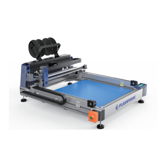
1.1 Equipment Introduction 1.1.1 Equipment View Filament spool Spool holder Fliament hole Mounting bracket Y-axis linkage Y-axis guide X-axis guide Z-axis sensor Teflon tube connector Heat sinks Cooling fan Heating block Nozzle... - Page 9 Z-axis motor Mounting hole Filament detection sensor Decorating part Filament feeding motor X-axis motor X-axis sensor Drag chain Y-axis sensor Power switch Ethernet port Touch screen Printing platform Extruder cover Support bracket 0.5m 0.5m The distance of device placement spacing at least 0.5 m.
- Page 10 The printing volume refers to the length *width* height of the build model. The maximum printing volume of AD1 Ad word 3D printer is Printing volume 600*600*70mm. You can’t directly build models that exceed this parameter.
- Page 11 ≤200mm/s Idle speed Display size 4.5 inches Extruder ≤260°C temperature Aluminum plate/glass Printing plate ( Flashforge does Build plate platform ≤100°C, by 4 areas not provide glass plate.) temperature Advertising supplies; Manual adjustment, 8 Leveling Filament Advertising PLA supplies;...
-
Page 12: Accessories
Mounting bracket Spool holder *2 AD1 / 广告字3D打印机 SZ21-CN/EN-A01 Quick Start Guide 快速启动指南 中文P01 。 This guide is only applicable to FLASHFORGE AD1 3D printer 本手册仅适用于闪铸科技 AD1 3D打印机 Tube connector Grease*3 After-sales Service Card Quick Start Guide Stamping wrench*3 Allen wrench*3 8mm/13mm 1.2mm/2.5mm/5mm... -
Page 13: Equipment Installation
1.3 Equipment Installation 1.Mounting support 1.Lift the equipment to the shelf or table before installation; reserve a corner before installing the support. 2.Rotate the support clockwise to the bottom. Install the 4 supports in sequence. 3.Shake the equipment by hand to check whether it shakes, and adjust the height of the supports to make the 3D printer stand smoothly. - Page 14 3.Use an Allen key to secure the 4.Place the two black tray shafts on the left U-shaped sheet metal bracket to the left and right sheet metal brackets. and right brackets with 4 M3 screws. 5.The tray rack and the bracket after 6.Connect the 3D printer to the 220V power assembly are shown in the figure.
-
Page 15: Equipment Settings
1.4 Equipment Settings After the equipment is installed, you need to perform a series of settings before printing. 1.4.1 Extruder calibration Before the calibration, it is necessary to confirm whether the motion state of the equipment is normal. 1 . Click Tools - Home. At this moment, you can check whether the basic status of the equipment is normal. - Page 16 4.The platform has 8 leveling points in total. Manually slide the extruder to the positions of 8 points as shown in the figure (except for the middle position, which is the leveling reference point). Insert the leveling paper at each point in turn, and use the stamping wrench at the bottom nut to adjust the height of the platform to make the nozzle just in contact with the platform.
- Page 17 1.4 设备设置操作 1.4.2 Installing Filament Load the filament into the spool holder on the left and right side respectively, pass the filament holes through the left and right filament detecting switches respectively, and then thread into the filament feeding motor until the filament reaches the nozzle.
- Page 18 1.4 设备设置操作 1.4.3 Feeding Filament 1.Click on the screen - Tools - Extruder L or Extruder R - Load. 2.After clicking, the extruder will heat up. Do not touch the lower part of the nozzle in order to avoid burns. The left filament and the right filament need to be fed separately, and the extrusion length of left and right extruder is about 100 mm.
- Page 19 1.4.4 Check the flatness of build plate Method for verifying extruder calibration and platform flatness: 1.Click Print - Select File AD1- leaving-check.gx file. (This step is only for inspection and not required) 2.The equipment starts to print the pattern. If the pattern adheres to the platform...
- Page 20 1.4.5 Glass Plane Installation Special Note: 1. Since glass plate is easy to break and Flashforge does not sell glass plate, you can purchase 620*620*5mm glass for printing in local market. When making super word, some users may need glass curing. Flashforge recommends 5mm non-tempered glass;...
- Page 21 1.4 设备设置操作 1.4.6 Glass plate Installation The glass installation method is as shown below: Take out the options for glass mounting. If the textured paper on the platform aluminum plate is damaged before installation, please remove it. 1. Remove the textured paper from the edge of the original aluminum plate, pass the M4 countersunk screw through the aluminum plate and lock the metal clip under the aluminum plate with M4 lock nut.
-
Page 22: Equipment Interface
1.5 Equipment Interface 1.5.1 Printing Click the Print button and choose the path to read the print file: 1. Read from the printer’s memory card; 2. Read the print file from the external USB flash drive; 3. Back: Return to the previous interface. Select the print file in the file list: 1. - Page 23 Temperature adjust: When the nozzle temperature in the page is underlined, click to change the nozzle temperature. Printing speed: Can be modified during printing; Filament: Click the Filament button when you need to change the filament in the process of printing (this function is available when printing pauses); Back: Cancel the tool command and return to the print interface.
- Page 24 1.5.2 Preheat Function Click the Preheat icon to enter the heating interface: 1. On/Off: Turn on/off the heating function for extruder or platform; 2. Temperature value: Click this icon to set the temperature; 3. Start: Click the Start icon and the extruder starts to heating up; 4.
- Page 25 1.5.3 Tools Click the Tools icon to enter the Tools interface: 1. Filament: Filament load or unload; 2. Home: Return the printer X/Y/Z axis to the mechanical home; 3. Manual: Manually adjust the position of the X/Y/Z axis; 4. Settings: Make related function settings for the printer; 5.
- Page 26 2. Resume Print: Set whether to continue unfinished file when the printer is lose the power, it will recovery print when the power back, the default option is ON;; 3. Flashforge Cloud: Turn off/on the Flashforge Cloud printing function; 4. Extruder calibration: Calibrate the initial distance between the extruder and the platform;...
- Page 27 Turn on [Resume Print] At this moment, the uninterrupted printing function is turned on. If the printer is turned off before the printing completes, the printer continues to print the unfinished model when the printer is turned on again. Turn off [Resume Print] At this moment, the uninterrupted printing function is turned off.
- Page 28 3. Open the Flashforge Cloud (cloud.sz3dp.com), click [Add Printer], enter the printer registration code in the pop-up window, and associate the equipment with the cloud platform. For details on how to connect the Flashforge Cloud, see the next chapter about printing.
-
Page 29: Equipment Printing
4. Cut the acrylic sheet according to the contour line; 5. Assemble the model and acrylic sheet. When printing with the AD1 light-emitting shell 3D printer, it is necessary to use the luminous character slice software to produce the character shell file, and convert the character shell or graphic design file into a file identifiable by the 3D printer. -
Page 30: Obtaining The Shell File
2.2 Obtaining the Shell File FlashAD can directly generate text and the software has text input function; after clicking, input the desired text in the dialog box and select the desired font. Here is an example of generating text with software. ·... -
Page 31: Software Settings
2.3 Software Settings 2.3.1 Typesetting Display the size of the shell, and drag to change the size. Top/Bottom: Different types of characters appear after setting. Set the color of the shell layer. If only one color is set, the default is to print with the filament in the right tray. - Page 32 Tilt effect Mirror and invert effect Straight edge + bevel effect after X value is set 2.3.2 Glyph Settings Select Step for the top surface to set the height from the step to the top surface and the width required for the step. Top step effect Select Close for the top surface, and the top of the shell will be closed.
- Page 33 Select Chamfer for the top surface, and the curvature of the top surface will form a chamfer. The chamfer size is customized. Top chamfering effect Select Close for the bottom surface, and the bottom of the shell will be closed. Bottom closure effect Select Widen for the bottom surface, the bottom will have an outer edge, which depends on the setting.
- Page 34 Select Bracket for the bottom surface and there will be a bracket between the shells, which is conducive to the shell adhesion. Bottom bracket effect Select Step for the bottom surface to set the height from the step to the bottom surface and the width required for the step.
- Page 35 2.3.3 Text Color Layering Settings Click this button to set the color of the shell layer. Represent: Monochrome printing Two-color printing Two-color interlacing Two-color cycle interlacing Two-color free cycle interlacing Take the three-layer color separation printing as an example: set the first layer to orange (indicating that the first layer is printed with the right extruder;...
- Page 36 Text color layering effect 2.3.4 Moving, Rotation and Zooming Settings Select the Move button, an arrow appears Select the Zoom button to change the font on the word, click the arrow or drag the size; click the arrow to zoom by one text directly to appropriate position.
- Page 37 2.3.5 Contour Line Settings Use FlashAD software to generate 3D text model: Click “Outline” to pop up the “Outline” window. The 3D model is divided into four types of contour lines: top interior, top exterior, bottom interior and bottom exterior. In order to achieve different requirements, the scaling factor of the contour line can be set (value range: -5%~5%, two decimal places).
- Page 38 Specific description of exporting contour line • When creating a model with a “step”, it is recommended that the height of the step is slightly larger than the thickness of the acrylic sheet to prevent shedding. For example, if the thickness of the acrylic sheet is 2mm, set the step to 3.0mmX1.6mm, as shown in the figure.
- Page 39 Specific description of cutting acrylic sheet The contour line is exported in plt format and opened or imported in the relevant software to check if it is complete and correct. Contour lines are typically imported from CorelDRAW. In addition, there are many types of cutters on the market. In order to ensure the accuracy, it is recommended to use a laser cutter to cut the contour lines.
- Page 40 Acrylic sheet assembly When assembling, put the model in the bottom and the acrylic sheet on the top, align the edges and corners, press as a whole to avoiding falling and light transmittance, and then apply glue for reinforcement. Instructions: •...
- Page 41 Contour line initial calibration There are many parameters of the cutter. Different parameters and different precision will produce different errors; different supplies have different shrinkage rates, and the model will also produce errors when printing. Therefore, please calibrate the contour line before use.
- Page 42 2.3.6 Adding Printer Settings Click Print and the page will go to the print interface. Click Add Printer to associate the equipment to FlashAD and the cloud platform. Find the registration code on the About page and enter it in the dialog box. Enter the equipment name, which can be customized.
- Page 43 2.3.7 Shell Placement Mode Setting The shell is broken up and printed in one stroke. For example, the character “i” will be automatically divided into 2 shell parts. When this mode is selected, the surface of the model is smoother and has no seams, which is more beautiful.
- Page 44 2.3.8 Model List Description The model list allows printing the current shell or not; click to check or cancel; when unchecked, the model is hidden and will not be printed.
- Page 45 2.3.9 Generating Print Task Click to generate a print task and a pop-up window will appear. Standard print settings Advanced mode settings File Name: The file name can be changed for subsequent differentiation. Print Quality: Select low, standard or high; the lower the quality, the faster the printing speed is;...
- Page 46 Form a triangular structure; Form a hexagonal structure; Form a wave shape structure; Density: Indicate the density of the texture. Path Slice: The software selects path as the default slice mode to have better print quality. V Shape Edge: When this option is selected, a V-shaped edge will be printed on the outer edge of the shell to increase the adhesion to the platform.
- Page 47 Retraction Speed: The speed of the filament pulled back to the nozzle when the extruder is lifted; increasing the pullback speed will reduce wiredrawing. Retraction Length: The length of the filament pulled back to the nozzle when the extruder is lifted; increasing the pullback length will reduce wiredrawing. Setting a large pullback length will result in filament shortage.
- Page 48 Combine Area Threshold: When larger shell and smaller shell are printed at the same time, higher speed will result in insufficient cooling of the small shell and affect the shell quality. Setting this value means that when the path of the shell is less than the value, the equipment automatically reduces the print speed to ensure the print quality of the small shell.
- Page 49 2.3.10 Print Shell Size and Shell Wall Thickness Parameter Settings Print shell size Print speed Print temperature (Ad PLA) <15 cm 30-40 mm/s 210-220 ℃ 15-20 cm 40-50 mm/s 215-220 ℃ 20-30 cm 50-55 mm/s 215-220 ℃ 30-40 cm 55-60 mm/s 220 ℃...
- Page 50 As described above, the actual thickness is slightly different from the theoretical calculation. The following data are measured values for reference: (1)0.6 mm:set nozzle:0.6,thickness:0.6, flow rate:100%,Wall thickness is too thin,we don’t recommended,suggest set flow rate:120%, print thickness is 0.7mm (2)0.8 mm:set nozzle:0.6,thickness:0.6, flow rate:140% (3)1 mm:set nozzle:0.6,thickness:0.6,...
- Page 51 Insert the USB flash drive into the equipment, click the file in the USB flash drive, click the Copy button, copy the GFZ file into the memory, and then return to the file in the memory for printing. After copying to memory, the file suffix is .g, which can be recognized by the device and printed.
-
Page 52: Maintenance And Support
USB flash drive; unplug the USB flash drive. 3. Insert the USB flash drive into your computer and open the USB flash drive folder to find the log file. 4. Please send the log file and equipment serial number to Flashforge Customer Service. -
Page 53: Maintenance And Overhaul
3.2 Maintenance and Overhaul Problem Cause Corrective measures Model can’t adhere The platform is not Please follow the instructions to calibrate to the platform flat, or the extruder the extruder and level the platform; other calibration value is simple methods: attach blue tape for deviated compensation in position with large gap. -
Page 54: Daily Maintenance
5. When the equipment is used for the first time or the printing supplies are replaced, only use official consumables of Flashforge until the extruded supplies are the same color as the loaded supplies. 6. If the equipment isn’t used, pay attention to avoid dust. -
Page 55: Help And Support
The professional after-sales and sales team of Flashforge is always on call. We are willing to solve any problems you may have while using AD1. If you can’t find a solution to your problem in this guide, you can visit our official website, or contact us by phone or In our official website, you can find the descriptions and solutions of some common... - Page 56 前言 注: 每台3D打印机在出厂前都经过打印测试,若设备喷头内存在耗材残留或打印平台有轻微划 痕,都属正常现象,不影响使用。 尊敬的闪铸用户, 感谢您选择、使用闪铸科技的产品。感谢您对闪铸科技的大力支持和帮助。 闪铸科技的产品质量优质、性能上佳。为了您使用方便,请您在使用之前仔细阅读本说明书, 并严格按照说明书的指示进行操作。整个闪铸科技团队时刻准备为您提供最优质的服务。在使用过 程中无论遇到什么问题,请按照说明书结尾所提供的电话、邮箱与我们进行联系。 为了您能够更好地体验我们的产品,您还可以从以下途径获取设备的操作知识: · 闪铸中文官网: 闪铸的官方网址:www.sz3dp.com 您可以登陆闪铸官网寻找相关软硬件、联系方式、设备操作、设备保养等信息。...
-
Page 57: 安全说明
安全说明 请确保认真阅读以下安全提示 工作环境安全 请保证打印机的工作台面干净整洁。 请保证打印机工作时远离可燃性气体、液体及灰尘。(设备运行产生的高温有可能会与空气中 的粉尘、液体、可燃性气体反应引发火灾) 儿童及未经培训的人员请勿单独操作设备。 用电操作安全 请务必将设备接地;切勿改装设备的插头。(未接地/未正确接地/改装插头必然会增加漏电风 险) 请勿将设备暴露在潮湿或烈日的环境中。(潮湿的环境会增加漏电的风险/暴晒会加速塑件老 化) 请勿滥用电源线,务必使用闪铸科技提供的电源线。 切勿在雷雨天气使用设备。 如长时间不使用设备,请关闭设备并拔下电源线插头。 拆装喷头等部件时请勿带电操作,请务必关机操作。 个人操作安全 在设备运行时,请勿触碰喷头、平台等位置。以免高温烫伤或机械碰撞 在打印刚完成时,请勿触碰喷头。避免高温烫伤 在操作设备时,请勿穿戴围巾、口罩、手套、珠宝装饰等容易卷入设备的物件。 请勿在饮酒、服药之后操作设备。 设备使用提示 切勿长时间离开正在运行的设备。 请勿自行对该设备进行任何改装。 请在通风的环境下操作设备。 请勿利用该设备进行违法犯罪的活动。 请勿利用该设备制作食物储存类产品。 请勿利用该设备制作电器类产品。 请勿将打印模型放入口腔。 请勿用蛮力卸下打印模型。 请勿使用长度大于3米的网线连接本设备。 设备若不使用请退出喷头中的耗材。 设备若长期不使用请使用防尘布遮盖。 当蓝色美纹纸对字壳的粘附性变弱时,请更换蓝色美纹纸。... - Page 58 设备运行环境要求 温度:室温15-30℃为宜 湿度:20%-70%为宜。 设备维护 长时间使用设备可能出现异响,请定期在导轨处以及丝杆处涂抹润滑油,建议是两周一次。 设备放置要求 设备需要放置于干燥通风的环境中。设备左侧和后侧必须要留至少20cm的距离,前侧必需要留 至少35cm的距离,右侧必须要留至少40cm的距离。 设备兼容耗材要求 在使用该设备时,请使用闪铸提供或指定的耗材。第三方耗材可能容易造成喷头堵塞及喷头损 坏。 耗材储存要求 除非需要使用耗材,否则请勿轻易将耗材拆封。拆封后请保持储存环境干燥,无尘。 法律禁止项目 请勿复制或打印法律禁止复制的任何项目。 复制受版权保护的作品。一些受版权保护的作品可以被部分复制以进行“合理使用”。多份复 制将被视为不正当使用。艺术作品等同于受版权保护的作品。 以上列表仅作参考,并不包括所有内容在内。对于其完整性及准确性,本公司概不承担负责。 如果您有与复制或打印某些项目的合法性相关的问题,请咨询法律顾问。 法律申明 用户无权对此使用手册进行任何修改。 客户若自行拆装或改造设备造成任何安全事故,闪铸科技概不负责。未经闪铸科技允许,任何 人不得对该手册进行修改或翻译。本手册受版权保护,闪铸科技对本手册保留最终解释权。 @Copyright 2018 浙江闪铸三维科技有限公司 版权所有...
-
Page 59: 第一章 设备介绍
第一章 设备介绍 总体概述 3D打印机技术即将三维模型转化成实物的技术。最常见的3D打印技术被称为FFF(Fused Filament Fabrication),即熔丝制造技术,AD1广告字打印机的应用技术即FFF。其工作方式是通 过高温融化丝状耗材,耗材降温后固化,通过耗材逐层叠加形成立体物品。 打印步骤 3D打印包括三个步骤,即获取模型、处理模型及打印模型。使用设计软件文字或图案的文件, 导入FlashAD文件处理软件,文件切片处理后将文件通过U盘或无线传输发送至打印机,开始打 印。 闪铸AD1是用于制作发光字字壳的3D打印设备,有效提升发光字制作效率,减少人工。 闪铸FlashAD软件是运用在闪铸广告机上的一款软件,具有生成3D模型、导出轮廓线、生成切 片文件三大功能,用于广告字的制作。 配套发光字字壳制作所需的PLA耗材(建议室内使用)以及广告专用耗材(可室外使用)。 广告字的制作步骤: 1、生成3D模型; 2、导出轮廓线; 3、生成3D模型的切片文件、打印模型; 4、按照轮廓线切割亚克力板; 5、模型和亚克力板的装配。 用户可通过CorelDRAW等设计软件,将字体或图案设计完成,保存导出cdr格式的字体或图案 文件,当前FlashAD广告机专用软件导入格式支持stl、cdr、nc三种格式。后续若软固件升级,可 支持更多格式。 FlashAD > > 软件设计 软件切换 设备打印... -
Page 60: 设备介绍
1.1 设备介绍 1.1.1 设备视图 料盘 料盘轴 过丝孔 料盘架 Y轴联动装置 Y轴导轨 X轴导轨 Z轴传感器 气管接头 喷头散热块 喷头风扇 喷头加热块 铜喷嘴... - Page 61 联轴器 料盘架安装孔 Z轴电机 装饰件 丝料检测开关 X轴电机 进丝电机 X轴传感器 拖链 Y轴传感器 电源开关 以太网口 触控屏 打印平台 喷头罩 脚架 0.5m 0.5m 设备摆放间距至少0.5米。...
- Page 62 1.1.2 术语说明 打印平台 用于构建实体模型的部分。 闪铸打印贴纸能够粘贴在打印平台上,目的是能够让打印模型更好地粘贴 在打印平台上。当平台贴纸开始影响打印效果的时候,请及时更换。即附 平台贴纸 赠的美纹纸。 打印体积是指构建模型的长*宽*高。AD1 广告字3D打印机最大打印体积为 打印体积 600*600*70mm。用户不能直接构建超过该参数的模型。 调平螺母 平台支架下的8颗调平螺母用于调节打印平台和喷嘴的间距。 喷头 将耗材从进丝孔导入、加热,再从喷嘴挤出。 喷嘴 构成喷头的最下部的黄铜色金属结构,经过喷头加热的耗材从该处挤出。 喷头风扇 喷头风扇用于降低喷头运作时的温度及加速耗材的凝固。 进丝孔 耗材进入喷头的入口,位于喷头顶部。 料盘架 放置耗材的装置,位于打印机背部。 导丝管 将耗材从丝盘盒引入喷头的白色塑料细管。 通针 用于疏通喷头,清理喷头中残余的耗材。...
- Page 63 1.1.3 设备参数 功能/规格 参数 功能/规格 参数 喷头结构 双进丝,单喷嘴。 堆积成型 打印机类型 Deposition Modeling 喷嘴孔径 0.6mm 丝料直径 1.75mm 中文,English,日本語 语言 成型尺寸 600*600*70mm ±0.5mm或0.2% 打印精度 AD1-220V 额定电压 AD1-110V 层厚 0.1~0.4mm 支持文件格式 Gfz,Stl,Nc,Cdr AD1-220V-1500W 功率 AD1-110V-1000W 使用温度 15~30℃ 切片软件 打印速度 FlashAD 最高150mm/s 显示屏尺寸 空走速度 最高200mm/s 4.5英寸...
-
Page 64: 产品配件
1.2 产品配件 电源线 U盘 料盘架 料盘轴*2 AD1 / 广告字3D打印机 SZ21-CN/EN-A01 Quick Start Guide 快速启动指南 中文P01 。 This guide is only applicable to FLASHFORGE AD1 3D printer 本手册仅适用于闪铸科技 AD1 3D打印机 气管接头 润滑脂*3 售后服务卡 快速启动指南 开口扳手*3 内六角扳手*3 一字螺丝刀 通针 8mm/13mm 1.2mm/2.5mm/5mm 铲刀... -
Page 65: 设备安装
1.3 设备安装 1.安装支脚 1.安装前先将设备抬至货架或桌子上;安装支脚前需先预留一个角落,以便安装。 2.按顺时针旋转直接将支脚旋至底。依次安装上4个支脚。 3.用手晃动设备不会摇晃,调整支脚高度,使3D打印机放置平稳。 2.安装料盘轴与料盘 1.将4颗M3螺丝以及对应M3弹垫取出;将4颗 2.使用内六角扳手,将左右钣金支架通过4颗M8 M8平圆头的螺丝以及对应弹垫垫片取出;取 的螺丝其固定到设备上。 出料盘支架的零件,将左右钣金支架安装到 设备中。... - Page 66 3.使用内六角扳手将U型钣金支架通过4颗M3 4.将两个黑色料盘轴左右钣金支架上。 螺丝固定到左右支架中。 5.料盘架以及支架整机装配完成后如图所示。 6.通过电源线将3D打印机连到220V电源上。 7.按下开关按钮,开机启动,此时设备安装完成。...
-
Page 67: 设备设置操作
1.4 设备设置操作 设备安装完成后,需要先将设备进行一系列的设置,方可打印 1.4.1 喷头校准 首先需要进行喷头校准设置,在喷头校准前需要先确认设备运动状态是否正常。 1 . 点击工具-回零。此时可查看设备基础状态是否正常。设备自动会运行至零位。 2.点击工具-设置-喷头校准。喷头会下降至平台处,使用调平纸,将纸塞入喷嘴与平台之间, 点击屏幕中的加减号校准喷头与平台的距离。点击加号喷头抬升,点击减号喷头下降。调平 纸移动有摩擦感受即视为喷头与平台当前处于合适位置。 点击确认按钮。 3. 点击确认按钮后,显示屏会出现Z轴电机已锁定的状态,此时不要点击完成按钮。出现此状 态后,利用随箱的调平工具对平台进行调平。(具体方式也可详见调平操作视频)... - Page 68 4.平台总体有8个可调平的点, 依次手动滑动喷头至如图8个点位置(中间位置除外,中间点 位置是作为调平基准点)。依次在各点位置处插入调平纸 ,在底部螺母处使用开口扳手调整平 台高低,使得喷嘴与平台刚好接触。 5.在配件中拿出开口扳手调节对应底部调平点。 顺时针拧开口扳手,平台下降,间隙变大。 逆时针拧开口扳手,平台上升,间隙变小。 6.调平完成后,点击屏幕的完成按钮,喷头会抬升。 调平操作详细请查看调平视频(随设备附赠的U盘中)用于辅助参考。...
- Page 69 1.4 设备设置操作 1.4.2 安装打印耗材 将配套的丝料装入料盘架,左右各一卷料盘,并将料盘上的丝料分别穿过左右丝料检测开关, 再穿入进丝电机,直到丝料到达喷嘴。 注意:请务必将左右丝料都装入喷头,否则有堵丝风险或出丝异常。...
- Page 70 1.4 设备设置操作 1.4.3 进丝 1.点击屏幕中-工具-换丝-左丝料-进丝。 2.点击进丝后,喷头会加热,此时请勿触碰喷嘴下部,以免烫伤; 左丝料与右丝料分别都需要进行进丝,左右喷头各需要丝料挤出长度约100mm。 注意:当只需要打印一个颜色的丝料时,也请在左右喷头中都进丝,打印时可在软件中 设置只打印一种耗材;若左右侧喷嘴腔有一处空缺可能会导致喷头堵或者打印不良。...
- Page 71 1.4 设备设置操作 1.4.4 检验平面度 检验喷头校准以及平台平面度的方法: 1.点击打印-选择文件 AD1- leaving-check.gx 文件。 (此步骤仅是检验作用,非必须的操作步骤) 2.设备开始打印图案,若图案粘附在平台上,图案无松散起翘等现象说明平台平面度良好。...
- Page 72 1.4 设备设置操作 1.4.5 玻璃平面安装 特别说明: 1. 由于玻璃运输容易破碎,闪铸不额外售卖玻璃,用户可自行采购620*620*5mm的玻璃用 于打印,制作超级字时部分需要直接带玻璃固化的用户可选择玻璃打印。闪铸推荐使用5mm 不钢化的玻璃; 2.安装玻璃前请务必先进行喷头校准,以免喷头磕到玻璃。 校准方式: 根据玻璃厚度H,将Z轴坐标设置为H+1MM,例如玻璃为5mm厚,将Z轴坐标值设置到6mm。 1.点击工具-设置-喷头校准 2.Z轴坐标设置到6的时候,直接点击确认, 出现Z轴电机已锁定的提示后,无需其它操作,直接点 击完成。...
- Page 73 1.4 设备设置操作 1.4.6 玻璃平面安装 玻璃安装方式如图所示: 拿出玻璃安装的选配件,安装玻璃前如平台铝板上的美纹纸已起翘破损,请撕除。 1.将原先铝板上的靠近边缘处的美纹纸撕除,用M4的沉头螺丝穿过铝板用M4锁紧螺母将 金属卡扣 锁在铝板下方。 2.将直角固定块通过M4圆柱头螺丝固定在铝板后方的基块上 。 3.将玻璃放到铝板上方,用金属卡扣扣住。 4.玻璃安装完成后,再进行一次常规的平台面与喷嘴的校准操作调平。校准后即可正常打印。...
-
Page 74: 设备界面
1.5 设备界面 1.5.1 打印 点击打印按钮,选择读取打印文件的路径: 1. 从打印机本地存储卡中读取; 2. 从外接U盘中读取打印文件; 3. 返回:返回上一界面。 在文件列表中选择打印文件: 1. 打印:开始打印; 2. 复制:将U盘中的文件复制到打印机本地存储卡(选择本地存储卡打印时此功能不可用); 3. 删除:删除此打印文件; 4. 返回:返回上一界面。 5. 列表中的绿色文件:表示此文件已被打开过。 取消:取消此次打印工作; 暂停/开始:暂停打印/开始打印; 工具:打印过程中可实时查询或更改:底板温度、打印时间、Z 轴坐标、丝料使用 量、打印速 度、换丝设置。... - Page 75 喷头温度:当页面中喷头温度出现下划线时,点击可更改喷头温度。 打印速度:打印过程中可进行修改; 换丝:打印中途需要换丝时可点击 换丝按键(暂停打印后该功能可用); 返回:取消工具命令,返回打印界面。 修改打印速度: 开始打印后,点击打印速度数值,可对个位,十位,百位分别修改设定打印速度数值,点击是 保存设定值;点击否取消设定。 字壳质量与打印速度有较大关联,字壳需要冷却时间,速度过快,冷却不足会导致字壳模型坍 塌,影响字壳质量。...
- Page 76 1.5.2 预热 点击预热图标,进入预热界面: 1.开/关:打开喷头/加热平台预热功 能,关闭喷头/加热平台预热功能; 2.温度数值:点击该图标可进行预热 温度的设定; 3.开始:点击开始图标,喷头开始预 热; 4.返回:返回到上一界面。 底板1,2,3,4 对应设备如图 (屏幕靠近底板4) 喷头/加热平台加热界面: 1.实际温度值/目标温度值; 2.停止:可暂停预热; 3.返回:返回上一界面。...
- Page 77 1.5.3 工具 点击工具图标,进入工具界面: 1.换丝:进行进丝/退丝操作; 2.回零:使打印机 X/Y/Z 轴回到机械原点; 3.手动调节:手动调节 X/Y/Z 轴的位置; 4 设置:对打印机进行相关的功能设置; 5.状态:查看打印机的实时状态; 6.关于:查看打印机的版本信息等; 7.返回:返回上一界面。 点击手动调节图标,进入手动调节模式: 1. Y+:喷头往 Y 轴正方向移动,即向后; 2. Y-:喷头往 Y 轴负方向移动,即向前; 3. X-:喷头往 X 轴正方向移动,即向左; 4. X+:喷头往 X 轴负方向移动,即向右; 5. Z+:平台向上移动; 6. Z-:平台向下移动; 7. 返回:返回上一界面。...
- Page 78 点击设置图标,进入设置界面: 1.语言:设置打印机显示语言; 2.恢复打印:设置断电后再开机是否继续未完成的打印,默认建议打开; 3.闪铸云:关闭/开启闪铸云连接打印功能; 4.喷头校准:校准喷头与平台的初始距离; 5.保温设置:打印完成平台仍处于保温; 6.Z轴补偿:喷头校准的扩展功能。调平后,若打印字壳时喷嘴距离平台有略高或者略低的现 象,请使用该功能进行微调差异,可以直接输入数值,调整喷嘴与平台之间的间隙。不熟悉设 备情况下不建议调整。 7. 开机声音:打开/关闭机器开机声音; 8. 丝盘检测:打开/关闭丝料检测功能; 当开启此功能时,若检测到无丝料或者丝料使用完,打印将会自动暂停。 9.玻璃平台打印:打开玻璃平台打印模式后,平台不再分区加温,4个区域同时加温,防止玻 璃因受热不均而破裂; 10.静音打印:打开/关闭静音打印功能; 11.恢复出厂设置 :回到出厂时的设置 ; 12.升级:在线升级最新的固件,若设备已连入有线网,可点击进行在线升级。 打开【恢复打印】 此时是断电续打功能开启状态,打印未完成时关机再开启,打印机会继续打印未完成的模型。 关闭【恢复打印】 此时是断电续打功能关闭状态,打印未完成时关机再开启,打印机不会继续打印未完成的模型。...
- Page 79 闪铸云连接 1.打开/关闭【闪铸云】 2.在【设置】-【关于】页面找到本台机器的注册码。 3.打开闪铸云(cloud.sz3dp.com),点击【添加打印机】,在弹窗中输入打印机注册码, 即可将设备关联云平台。 闪铸云的详细连接方法请参见下一章关于打印。 状态 点击状态按钮,可查看设备当前喷嘴预计平台的温度,以及喷嘴当前的坐标值。 关于 显示设备基本信息,信息详情以设备实际显示为准。 可查看设备固件版本号;打印体积大小;累计的打印时长等。 以太网的IP地址:当连接上网线时,此处会显示以太网的IP地址、以太网的MAC地址。 说明:在申请售后服务时,需将【关于】中的序列号提供给售后工程师。 说明:设备固件定期更新,部分界面有差异属正常现象。...
-
Page 80: 第二章 设备打印
第二章 设备打印 2.1 打印配套软件 FlashAD软件是运用在闪铸广告机上的一款软件,具有生成3D模型、导出轮廓线、生成切 片文件三大功能,用于广告字的制作。 广告字的制作步骤: 1、生成3D模型; 2、导出轮廓线; 3、生成3D模型的切片文件、打印模型; 4、按照轮廓线切割亚克力板; 5、模型和亚克力板的装配。 在使用AD1发光字壳3D打印设备打印时,需要使用发光字配套切片软件进行字壳的文件制 作,将字壳或图形设计文件转化为3D打印设备可识别的文件。 2.1.1 获取软件 获取软件途径: 随机的U盘可复制FlashAD软件或请登录www.sz3dp.com获取最新版本的软件。 打开FlashAD广告字专用软件,点击右上角用户登录按钮, 点击注册云账号,将会跳转至云 平台网页进行注册,或直接登陆https://cloud.sz3dp.com,注册闪铸云账号。... -
Page 81: 获取字壳文件
2.2 获取字壳文件 FlashAD可直接生成文字,软件中自带文字输入功能;点击后,在对话框中输入所需的文字, 选择需要的字体。 此处说明以软件自带文字生成举例。 · 用户可使用CorelDRAW 等软件制作的矢量设计图,导出以cdr格式的文件。将此文件导入到 FlashAD 软件中。 · 点击文字按钮,输入“闪”字,自定义字体及大小(若是cdr文件输出对字体大小会更直观)... -
Page 82: 软件设置
2.3 软件设置 2.3.1 字样设置 显示字壳大小,拖动可更改大小。 顶面/底面:设置后会出现不同的字样形式。 可设置字壳分层的颜色,若只设置一种颜色,默认为 右边料盘的丝料打印。 默认为0.8mm,此参数不需要设置。 代表所打印字壳的厚度,默认为0.8mm,数值越高, 字壳厚度越厚。 代表所打印字壳的整体高度,默认为20mm,数值越 高,字壳越高,设置支持最高70mm的高度。 代表所打印字壳的外圈比内圈高出的高度。 代表所打印字壳的与直边字打印时的倾斜角度,即为 斜边字打印,当字体大小越小时,倾斜角应设置的小,否则 容易打印失败。X表示底部直边的长度。 代表边缘鼓起的弧度,X表示距离上下边的高度。 通过一系列需要的设置后点击生成3D模型按钮,文字将会 从二维转化为三维字壳。 注意: 1.字壳模型倒放和镜像同时选择时,实现模型的倒立放置。 2.字壳设置为下部直边、上部斜边的字壳时,点击倒立和 镜像按钮,所设置的台阶将会失效。 3.当添加底部加宽时,设置倒置镜像时,会使得字壳模型 打印完成后底部加宽的部分呈现在字壳上表面。 倾斜图示 镜像与倒放图示 X值设置后,直边+斜边双重 效果图示... - Page 83 2.3.2 字形设置 选择顶面台阶,可设置台阶距离顶面的高度,以及台阶所需的宽度。 顶面台阶效果 选择顶面封闭,字壳顶部将会是一个封闭的面。 顶面封闭效果 选择顶面倒角,顶面的弧度会形成倒角,倒角大小根据自定义设置。 顶面倒角效果...
- Page 84 选择底面封闭,字壳底部将会是一个封闭的面。 底面封闭效果 选择底面加宽,底部将会有一个外沿的部分,外沿大小按设置。 建议外延0.8, 将有利于字壳粘附于平台。 底面加宽效果 选择底面支架,字壳体之间会有支架产生,有利于字壳粘连。 底面支架效果...
- Page 85 选择底面台阶,可设置台阶距离底面的高度,以及台阶的宽度。 底面台阶效果 2.3.3 文字颜色分层设置 点击此按钮可设置字壳分层的颜色。 分别代表:单色打印、双色打印、 双色交错、双色循环交错、 双色自由循环交错 以三层分色打印为例:设置第一层 为橙色(表示第一层使用右喷头打 印(这里的橙色只是用于区分左右 喷头,并不一定代表真实颜色), 若设置总高为30,下部颜色可在框 中设置高度,中间颜色框的数字为 第一分色加第二分色的高度;最顶 层颜色与第一分色的颜色相同;左 右喷头可点击色块切换。 例如:模型总高30mm,第一分色 设置6mm,第二分色设置20mm, 则说明第一分色高度为6mm,第二 分色高度为14mm,第三分色高度 为10mm; 其它分层原理与此类似。...
- Page 86 文字颜色分层效果 2.3.4 移动旋转缩放设置 选择移动按钮,字上出现箭头,点击箭头或者 选择缩放按钮,可更改字体大小;点击箭头为 直接拖动文字可将其拖动放置在合适位置。 单方向缩放,点击方块为整体缩放。 选择平台区块,对应底板1/2/3/4,默认放置 的底板区域为3号区域,当单字打印时可节省平 台加热的时间。...
- Page 87 2.3.5 轮廓线设置 运用FlashAD软件生成3D文字模型方法: 点击“轮廓线”,“轮廓线”弹窗显示。3D模型分为顶面内部、顶面外部、底面内部,底面外部4 类轮廓线,为了实现不同的需求可设置轮廓线的缩放系数(数值范围:-5% ~ 5%的两位小数)。 完成设置,点击“确定”,保存轮廓线。 点击轮廓线: 将会导出所需要雕刻面板的文件,该文件可导入激光雕刻机中,雕刻面板。 针对轮廓线和亚克力板的制作,可能遇到的问题及其解决方法,在此举例说明。 导出轮廓线具体说明 • 生成含有“台阶”模型时,为防止脱落,建议台阶的高度稍大于亚克力板的厚度。 如:亚克力板的厚度为2mm,台阶设置为3.0mmX1.6mm,如图。...
- Page 88 • 一些文字的轮廓间隙较小,在生成3D模型后,存在重合封闭现象,导出的轮廓线会有交叉、中断 现象。如图: • 含有倒角效果时,顶面外部的轮廓线不存在;顶面封闭时,顶面的轮廓线不存在;底面封闭时, 底面的轮廓线不存在。 切割亚克力板具体说明 轮廓线导出为plt格式,在相关的软件中打开或导入查看是否完整、无误。一般从CorelDRAW 软件中导入轮廓线。另外,市面上的切割机种类很多,为了保证精度,建议采用激光切割机,切割 时对准轮廓线进行切割。激光切割机种类很多,此处介绍普遍采用的火焰切割机。 • 由于火焰切割机温度不够均匀,所以亚克力板表面的温度会高一些,收缩率也比较高,切割面是 斜面。为了使亚克力板装配到3D模型时更容易一些,请先将轮廓线进行水平镜像,再进行切割。 • 3D模型打印时,边角部分有丝料堆积增厚现象,为了加大模型和轮廓线的匹配度,所以FlashAD 导出轮廓线时设置了0.8mm的圆角。如果切割机的精度不够,可能会视为直角。这时可对亚克力 板的边角做修剪,也可根据切割机的精度,在CorelDRAW软件中自行修改轮廓线的圆角。如图: 如上所述,轮廓线存在交叉、中断、间隙过小,切割时会出现断开,这是不可避免的。 • 如果不是激光切割机,在切割时请考虑刀具半径的补偿,例如:刀具的直径为4mm,切割时应 对准轮廓线向外或向内2mm的半径补偿。...
- Page 89 亚克力板装配 装配时,模型在下,亚克力板在上,边角对齐,整体按压,以不脱落、不透光为准,再涂上胶 水加强牢固。 有关说明: • 边角和弯曲的位置丝料堆积和变形程度不同,尤其是弯曲程度比较大和有倾斜效果的模型。会遇 到按压不进的情况,需要细节的用力挤压或亚克力打磨处理,也可修改轮廓线。如图: • 如上所述,模型有重合,轮廓线和亚克力板有中断现象,需要分开装配,效果如图,中断部位将 不会透光。...
- Page 90 轮廓线初始校准 切割机存在多种参数,参数不同,精确度不同,会产生不同的误差;耗材不同,收缩率也不 同,模型打印时同样会产生误差。所以,请在使用前做好轮廓线的校准工作。 校准方法: 1. 打开FalshAD,“金”,字体:stxingka,宽度:253mm,倒角:高度5mm,生成模型,导出 顶面内部的轮廓线;“历”,字体:Yuanti,长度:212mm,台阶:3.0mmX1.6mm,倾斜: 10,生成模型,导出顶面内部的轮廓线。 2. 分别打印模型,沿着轮廓线切割亚克力板,装配亚克力板,根据匹配程度,调整轮廓线的缩放 比例。若出现亚克力板偏大,加大缩放比例,如从-0.5%调整到-0.8%;相反,缩小缩放比例,如 从-0.5%调整到-0.2%,直至亚克力正好卡扣到模型内,不脱落,不透光。 2.3.6 添加打印机设置 点击打印,页面跳转到打印界面。 点击添加打印机,将设备关联到FlashAD以及云平台。 在设备关于页面中找到注册码,输入到对话框中。将设备名称输入,名称可自行定义。点击确 认设备即被关联。当设备未插入网线时,当前会显示离线状态,当设备插入网线后,设备会处 于在线状态。在线状态时,设置好的文件可直接发送至打印机打印。...
- Page 91 2.3.7 字壳摆放模式设置 字壳解体打印,字壳分体,均为一笔画打印,例 如闪字会被自动分隔成4个字壳部分。选择该模式 打印,模型表面更光滑,模型表面没有接缝,更 加美观。简单的字壳形状(圈状字壳)建议使用 该模式打印。 整字打印,按单个字体进行整体打印,打印完整 个字壳后再打印下一个字壳,当选择这个选项 时,底面会出现蓝色高亮标志;打印先后顺序为 打印完第一个字壳部分后,开始打印第二个字壳 部分。该打印模式可以将先打印完成的字壳先取 下制作。 字壳一体式打印,不会将一个字拆分成几部分。 该模式打印时生产效率较高,但字壳表面会产生 接缝。 字壳放置说明: 字壳默认放置于底板3的位置, 软件放置的区域为3-4-1-2; 用户可自行移动字壳位置。 字壳将按层打印,先打印第一个字壳的第一层, 再打印第二个字壳的第一层,再打印第三个字壳 的第一层。依次按层逐渐将字壳全部打印完成。 该打印模式需要全部字壳都打印完成才能取下字 壳。...
- Page 92 2.3.8 模型列表说明 模型列表可以选择当下字壳打印或者不打印,点击勾选或者取消,当不勾选时,模型隐藏,且 不会被打印。...
- Page 93 2.3.9 生成打印任务设置 点击生成打印任务,将会出现弹窗。 标准打印设置 高级模式设置 文件名称:可更改文件名,以便后续区分。 打印质量:可选择低/标准/高,质量越低,打印速度越快,质量越高,打印速度越慢,建议选 择标准模式。 打印材料:选择广告耗材时,底板和喷头温度默认95℃和230℃;打印耗材选择广告PLA时, 底板和喷头温度默认50℃和220℃;也可根据实际情况进行更改,参数设置对应字壳设置请查 看2.3.10打印字壳大小以及字壳壁厚对应参数设置方法 。 底板网格:帮助底板的粘附,需要底部特殊花纹时,可增加此选项,打印时间将会增加,一般 情况下不建议选择。该功能也可用于分散字壳间的连接,字壳取下时不会分体,也可以用于做 灌胶字,灌胶是分体的字壳不会偏移,若是用于连接,可将密度设置的小一些。 形成三角形状的结构体; 形成六边形状的结构体; 形成波浪形状的结构体; 密度:表示纹理的密集程度。 路径模式切片:软件默认选择切片模式为路径,将有更好的打印质量。 V型边:选择V型边时会在字壳外边缘打印一圈V字型的边,增大与平台的粘附;当打印大于 200mm 的字壳时建议将此设置勾选,能大幅的提升打印成功率,防止由于字壳未能粘附到平 台上的打印失败。...
- Page 94 高级:高级模式开放了更多的参数供用户设置。 层高:用户可自定义速度与层高。层高越高,层与层之间越分明;打印时长越短;建议设置层 高0.25-0.3mm。 出丝量:出丝量越大,喷嘴吐出的丝料越多,成型的字壳会变厚,起点速度建议为慢速。 打印速度:建议一般打印按40-50mm/s的速度打印,对应不同字壳设置,在下一页面中将有 详细的建议说明。 空走速度:未打印模型时,设备运行的速度。 Z轴抬升:空走时Z轴抬升的高度。 首层出丝量:首层出丝量的增加有利于第一层粘附于平台。 首层速度:第一层打印的速度,建议设置10-20mm/s,第一层速度若太快,丝料无法粘附在 平台上,容易打印失败。 回抽速度:表示喷头抬升时,丝料反抽回喷头的速度,增加回抽速度有利于较少拉丝现象。 回抽长度:表示喷头抬升时,丝料反抽回喷头的长度,增加回抽长度有利于较少拉丝现象。设 置较大回抽长度,会导致缺丝。 补偿速度:回抽后的补偿,回抽时速度要快,补偿回来的速度要慢。 补偿长度:对应回抽后对丝料的补偿长度,是为了防止字壳缺丝(若未有缺丝现象则可以不设 置)。 换色模式:选择换色墙,可选择输入换色墙坐标,也可默认设置;换色时,在打印第二个颜色 前将会先打印换色墙,然后再打印第二个颜色;以增加不同颜色之间材料的粘附。换色长度建 议大于300mm。 换色减速:指当两种颜色切换时,切换的颜色第一层的打印速度与常规打印速度的比例,速度 降低有利于材料间的附着。 换色长度: 两种颜色切换前,设置预吐丝的长度,当设置数值为0时,换色时不吐丝;当设置 数值为40时,则遇到换色层时另一个颜色将会先吐出40mm 的丝料(该功能防止换色时耗材 粘附不佳,开换色层开裂的问题)。 换色高度:指喷头更换颜色会进行吐丝的高度。 换色偏移:选择换色吐丝模式,设置偏移量,吐丝时喷头移开当下打印模型,移开距离为设置 的偏移距离。 换色位置X/Y:选择换色墙模式时两种颜色切换时,喷头将移到设定的X/Y 坐标位打印围墙。 减速面积:当较大字壳和较小字壳同时打印设置较高的速度,会导致小字壳冷却不充分,影响 字壳质量,设置该值表示当字壳运行的路径小于该值时,设备自动降低打印速度,以确保小字 壳的打印质量。 起点速度:在一体式打印的模式下,起点速度太快容易造成起点处缺丝,因此设置较慢的起点 速度,有利于保证字壳质量。该设置的值为常规打印速度的百分比。 起点距离:即设置起点速度后,对应运动的路径长度。 悬挂速度:打印台阶时的速度,速度越慢越利于台阶的粘附,建议设置30-50% 的值,悬挂速 度的计算方式为百分比乘以打印速度,不建议超过30mm/s。...
- Page 95 2.3.10 打印字壳大小以及字壳壁厚对应参数设置 打印字壳大小 打印速度 打印温度(广告PLA) <15 cm 30-40 mm/s 210-220 ℃ 15-20 cm 40-50 mm/s 215-220 ℃ 20-30 cm 50-55 mm/s 215-220 ℃ 30-40 cm 55-60 mm/s 220 ℃ 50-60 cm 60-70 mm/s 220-225 ℃ 备注:当打印字壳大小越小时,建议使用较低的打印速度,以便字壳有更好的冷却效果;表面 纹理更光滑。 字壳壁厚 设置方法(喷嘴直径与壁厚) 喷嘴直径:0.6 壁厚:0.6 0.6 mm 设置出丝量:100%...
- Page 96 如上描述为理论计算,实际厚度有所偏差,如下数据为实测值,供参考: (1)0.6壁厚参数:0.6喷嘴,0.6壁厚,100%出丝量,但容易出现小孔,建议出丝量120%, 实际为0.7的壁厚。 (2)0.8壁厚参数:0.6喷嘴,0.6壁厚,130%或140%的出丝量 (3)1.0壁厚参数:0.6喷嘴,0.6壁厚,160%的出丝量 (4)1.2壁厚参数:0.6喷嘴,0.6壁厚,200%的出丝量;0.8喷嘴,0.8壁厚,150%的出丝 量 (5)1.5壁厚参数:0.6喷嘴,1.2壁厚,100%的出丝量(两层,适合小模型);1.0喷嘴, 1.0壁厚,150%的出丝量(单层,适合大模型) (6)1.8壁厚参数:0.6喷嘴,1.2壁厚,120%的出丝量(两层) (7)2.4壁厚参数:0.8喷嘴,1.6壁厚,130%的出丝量(两层);0.6喷嘴,1.8壁厚, 120%的出丝量(三层,适合小模型、台阶和倒角模型) 2.3.11 切片文件传输设置 弹出打印切片窗口,切片完成后,可发送至打印机以及导出切片文件至U盘。...
- Page 97 在设备中插入U盘,点击U盘中的文件,点击复制按钮,将GFZ文件复制到内存中,再返回点 击内存中的文件进行打印。复制到内存后的文件后缀为.g可被设备识别,打印。 在任务界面中可查看打印打印机是否忙碌,当打印机未忙碌时,直接发送文件后可直接打印。 若当前打印机在忙碌状态,新的文件将会排入到任务列表中,当前一个字壳打印完成后可继续 点击打印。 该界面中显示任务的名称,剩余打印时间,喷头和底板温度,更多任务查看任务列表。 暂停:暂停当前打印任务 取消:取消当前打印任务 特别说明: FlashAD软件功能按一定周期更新,该设备说明书不会实时更新,软件更新时将会有更新说 明;可在官网(www.sz3dp.com)获取最新的FlashAD软件。...
-
Page 98: 第三章 维护与支持
第三章 维护与支持 3.1 拷贝日志 1.插入U盘,在设备的触摸屏右上角会出现 图标。 2.快速点击 图标3下,图标会跳动一下, 说明日志已拷贝到U盘中,拔掉U盘。 3.把U盘插入电脑,打开U盘文件夹找到log文 件。 4.请把日志文件与设备序列号发给闪铸客服。 3.2 维护与检修 问题 原因 改正措施 请按说明书中校准喷头与平台的操作执行,平 平台不平,或喷头校 台调平与喷头校准;其它简便方法:可以使用 耗材无法粘附到平台 准值有偏差 蓝色胶带进行补偿,间隙较大的地方贴蓝色胶 带进行补偿。增加第一层的出丝量可以增大粘 附。 将喷头进行预热,手动推动丝料是否可以将丝 料挤出;若不行,按压气管接头的黑色弹片, 耗材无法正确挤出 查看喷头是否堵塞 取出导丝管,使用通针工具打喷头进行通塞处 理。 查看限位开关的状态,设备运动时有无碰撞到 1.限位开关线路故障; 限位开关,如果未碰撞到查看周边有无障碍物 喷头无法回到原位 2.有障碍物阻挡运行 阻挡。确认限位开关功能是否失效。若是请联 系售后服务。 确认电源完好通电的情况下若开机屏幕一直无 屏幕黑屏,点击没有 1.电源可能未上电; 响应,此时进行设备断电。... -
Page 99: 日常保养与维护
3.3 日常保养与维护 1.日常不使用设备期间,请盖上顶盖,关闭前门,避免设备落灰。长期未使用者,建议使用原厂包 装封存。 2.定期给运动部件上润滑油(通用润滑脂)。使用频繁者,至少每隔两周添加一次润滑油(脂); 长期不使用者,至少每4个月添加一次润 滑油(脂)。 3.每次打印结束,请及时清理打印平台上的轮廓线和其他杂物,避免影响下次打印的模型质量。 4.打印贴纸为消耗品,当打印平台贴纸附着力下降,或者破损;请及时更换打印贴纸。以免影响打 印效果。 5.首次使用设备或更换打印耗材后,请使用闪铸官方耗材,直到喷嘴挤出耗材与装入耗材颜色一 致。 6.设备若不打印,请注意防尘摆放。 3.4 帮助与支持 闪铸专业的售后及销售团队随时为您待命。我们非常乐意为您解决您在使用AD1过程中遇到的 任何问题。如果您无法从此用户手册中找到解决问题的方法,您可以访问我们的官方网站搜索解决 方法,当然您也可以通过电话或QQ联系我们。 在我们的官网中,您可以找到一些常见问题说明和解决方法。在视频栏中可找到对应产品的操 作视频。您的许多问题都可以在这里得到解决:http://sz3dp.com。 您可以在每周一到周六的上午8:00 ~下午5:00工作时段通过电话和QQ来联系闪铸的售后团队 为您解决问题。如果您在非工作时段联系我们,我们会在工作时段第一时间给您回复和反馈,解决 您的问题。若造成不便,我们万分抱歉。 注:由于更换不同的丝料,会有少量杂质残留在喷头中造成喷头堵塞,疏通后即可,不属于质量问 题,不在400小时寿命范围内,若用户使用时存在该问题请联系售后或当地经销商,并在售后的指 导下完成疏通工作。 售后服务热线:400-886-6023 售后邮箱:flashforge@flashforge.zohodesk.com / support@flashforge.zohodesk.com 售后客服QQ:2850862986 / 2850863000 / 2853382161 3D爱好者QQ群:149550566 / 206773820 公司地址:浙江省金华市婺城区仙源路518号... - Page 100 After-Sales Service: support@flashforge.com 售后专线:support@flashforge.com 400 886 6023...
Need help?
Do you have a question about the AD1 and is the answer not in the manual?
Questions and answers