Table of Contents
Advertisement
Quick Links
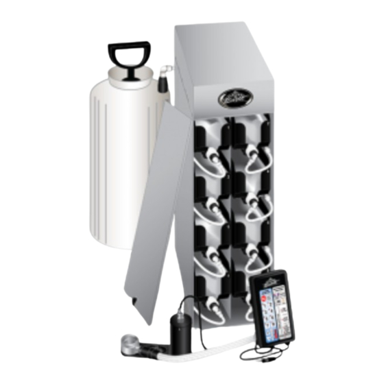
Flavor Burst
®
Frozen Beverage System
Model FB 80Sa
Equipment, Maintenance and
Operations Manual
Manufactured by
Flavor Burst Company
499 Commerce Drive
Danville, IN 46122
For general information and to locate a
distributor near you, call or visit our website:
Phone: (317) 745-2952
Toll Free Number: (800) 264-3528
Fax: (317) 745-2377
www.flavorburst.com
For pricing, ordering and support, contact one
of our qualified distributors.
Warranty
An installation and warranty form is provided with every FB 80Sa system, located inside the FB 80Sa
unit with this manual. It is important that the operator carefully review the warranty and installation
documents accompanying the unit before using this system. Any questions or concerns regarding the
warranty should be clarified upon delivery or installation. For more information, contact your local
authorized Flavor Burst
®
distributor.
©2022 Flavor Burst Company
Printed in April
Printed in
All Rights Reserved
The United States of America
Advertisement
Table of Contents

Subscribe to Our Youtube Channel
Related Manuals for Flavor Burst FB 80Sa


Summary of Contents for Flavor Burst FB 80Sa
- Page 1 Warranty An installation and warranty form is provided with every FB 80Sa system, located inside the FB 80Sa unit with this manual. It is important that the operator carefully review the warranty and installation documents accompanying the unit before using this system. Any questions or concerns regarding the warranty should be clarified upon delivery or installation.
-
Page 2: Table Of Contents
TABLE OF CONTENTS Introduction……………………………...………………………………………….………….3 Safety Precautions……………………………..…………….………..……..….…………..3 Environmental Notices………………...………………………………………….………….4 Parts Identification/Function……...……………………….……..…..……….……..….…..5 Daily Opening Procedures……..………………………….…….…..…….………..……...22 Sanitizing the Blending System………………………….….………………..…...…22 Assembling the Blending Assembly………………...…..………………………...…23 Installing the Blending System………………………………….……….……...…...24 Other items to check during opening procedures……………………………….…25 Daily Closing Procedures………………………………………….……………….………26 Removing the Blending System………………………………..……………...…...26 Disassembling the Blending Assembly………………..……………………….……27 Sanitizing the Blending System…………………………………..……………...…..28 Replacing the Syrup Flavors…………...…………………………..…….………...……...30 Scheduled Maintenance…………...……………………………….…….………...…..….34... - Page 3 Power Connections and Power Up…………………………………………..…58 Installing Flavors and Priming Syrup Lines………………………...………..…59 Keypad Overview.…….……………………..…………………………..…………..…62 Keypad Functions………………………………………..…..……...…………...……62 Accessing Serving Count..………..…….…………………………………...…..…64 Dispensing Flavor Burst Product..…….……………………………..…...…..…65 Adjusting the Flavor Level………..…….…………………………………..…..…65 Adjusting Multi-Flavored Timing..…….…………………………………..…..…67 Setting Serving Size Timing……..…….………………………………...…..…68 Directory of Cleaning Procedures……………………………...………………..…….….70 Parts Replacement Schedule………...………………….………………..….……………71 Recommended Maintenance Items Replacement Schedule………………..…..…72...
-
Page 4: Introduction
Failure to follow this practices in your daily operating routine. instruction may result in electrocution. The FB 80Sa series system is added to a frozen beverage freezer to blend concentrated DO NOT operate the system with larger flavorings throughout frozen beverage product fuses than specified on the system data label. -
Page 5: Environmental Notices
NOTE: Operations Manual subject to exposed to freezing temperatures. change. Contact your local distributor for most recent updates concerning the FB 80Sa unit. ENVIRONMENTAL NOTICES If the crossed out wheeled bin symbol is affixed to this product, it signifies that this product is compliant with the EU Directive for Waste Electric/Electronic Goods (WEEE) as well as other similar legislation in affect after August 13, 2005. -
Page 6: Parts Identification/Function
Supplies the electronics board with power. INJ 424VS VERTICAL BLENDING ASSEMBLY Blends syrups into frozen beverage. ELE 550 KEYPAD ASSEMBLY Flavor Burst unit command center. ELE 510 DRAW SWITCH ASSEMBLY Activates Blending Assembly. CAB 113 FLAVOR TRAY Houses syrup bags. - Page 7 General System Overview Figure 1...
- Page 8 Cabinet – (See Figure 2) ITEM PART NO. DESCRIPTION QTY. FUNCTION ELECTRONICS SYSTEM Control system for the unit. CAB 135R-A RIGHT SIDE PANEL Holds tray support brackets and panel brackets. CAB 145 TRAY SUPPORT BRACKET Supports flavoring trays. Fastens panel brackets to divider panel, secures FAS 2024 8-32 X 1/4 PAN HEAD sides.
- Page 9 Cabinet (Continued) ITEM PART NO. DESCRIPTION QTY. FUNCTION Provides spacing between cabinet base and RUB 618 RUBBER BUMPER WITH WASHER table. Attaches to screw and holds rubber bumper FAS 2035 8-32 NUTS - EXT. LOCK WASHER in place. MIS 3074 SHORTY PLUG #1672 Covers screw hole in rubber bumper.
- Page 10 Blending Assembly and Related Parts (See Figure 3) ITEM PART NO. DESCRIPTION QTY. FUNCTION VERTICAL BLENDING ASSEMBLY INJ 424VS WITH SYRUP LINES, ADAPTER, & Transports and blends syrup into product. BRACKET VERTICAL SHAKE BLENDING Connects flavor line to blend syrups into INJ 422VS HEAD ASSEMBLY product.
- Page 11 Blending Assembly and Related Parts (Continued) ITEM PART NO. DESCRIPTION QTY. FUNCTION BLENDING ASSEMBLY - NO INJ 323 Powers Blending system. HEAD 10A INJ 330 BLENDING MOTOR ASSEMBLY 1 ea. Supplies power to Motor which turns gears. BLENDING GEARBOX Gears turn Gear Cartridge for even syrup 10B INJ 331 1 ea.
- Page 12 PAGE INTENTIONALLY LEFT BLANK...
- Page 13 Blending Assembly and Related Parts Figure 3...
- Page 14 Syrup Pump and Related Parts (See Figure 4) ITEM PART NO. DESCRIPTION QTY. FUNCTION Pumps syrup from flavor bags to flavor SHAKE SYRUP PUMP lines. PERISTALTIC SYRUP PUMP - Pumps syrup from flavor bags into flavor SYR 926 1 ea. SHAKE lines.
- Page 15 Syrup Pump and Related Parts Figure 4...
- Page 16 CLEAR TUBING Transports sanitizer to Pump Flush Adapter. Holds sanitizer solution and delivers it to the SAN 740 SANITIZER TANK ASSEMBLY Flavor Burst cabinet and Blending Assembly. 12A SAN 701 SANITIZER TANK 1 ea. Holds sanitizer solution. HAND PUMP ASSEMBLY-FLUTED 12B SAN 734 1 ea.
- Page 17 Sanitizer Pump and Related Parts Figure 5...
- Page 18 Electronic Parts and Connections (See Figure 6) ITEM PART NO. DESCRIPTION QTY. FUNCTION ELE 550 KEYPAD ASSEMBLY Flavor Burst unit command center. ELE 510 DRAW SWITCH ASSEMBLY Activates Blending Assembly. Powers the Blending Assembly to blend INJ 330 BLENDING MOTOR ASSEMBLY syrup into product.
- Page 19 Electronic Parts and Connections Figure 6...
- Page 20 Spare Parts Kit (See Figure 7) ITEM PART NO. DESCRIPTION QTY. FUNCTION SPARE PARTS KIT – SPR 5800BEV Houses extra spare parts and wear items. TOUCHSCREEN BEVERAGE ELE 510 DRAW SWITCH ASSEMBLY Activates Blending Assembly. RUB 601 9-POS DUCKBILL CHECK VALVE Provides sealed cavity to prevent leakage.
- Page 21 Spare Parts Kit Figure 7...
- Page 22 PAGE INTENTIONALLY LEFT BLANK...
-
Page 23: Daily Opening Procedures
3. Remove each part from the sanitizer DAILY OPENING PROCEDURES solution. Place the items on a sanitary tray to air dry. ADDITONAL PRODUCTS & SUPPLIES REQUIRED: 26067 - STERA-SHEEN® GREEN LABEL SANITIZER - DAWN® DISH SOAP - APPROVED, SERVICEABLE AND SANITIZED TOOLS AND BRUSHES. -
Page 24: Assembling The Blending Assembly
6. The following do not need to be sanitized on 2. Install the Blending Head onto the Gear Box a daily basis as part of the daily opening and rotate off-center to secure. procedures. However, inspect these areas 26024 and if necessary, clean according to instructions in the SCHEDULED MAINTENANCE section: ... -
Page 25: Installing The Blending System
Installing the Blending System 4. Ensure that the Blending Assembly is level horizontally and make any adjustments to 1. Ensure the o-rings are installed on the spout the suspension bracket as needed using the adapter. Snap the adapter onto the freezer adjustment hand knob. -
Page 26: Other Items To Check During Opening Procedures
These steps do not necessarily need to be performed as part of the daily opening procedures. The following is a list of areas to check on the Flavor Burst system during ® opening procedures. These areas should be checked and adjusted if necessary. -
Page 27: Daily Closing Procedures
2. Rotate the 9-Tube Assembly coupler until it DAILY CLOSING PROCEDURES unlocks and is able to slide out of the Blending Head syrup line opening. ADDITONAL PRODUCTS & SUPPLIES REQUIRED: - STERA-SHEEN® GREEN LABEL SANITIZER - DAWN® DISH SOAP - APPROVED, SERVICEABLE AND SANITIZED TOOLS AND BRUSHES. -
Page 28: Disassembling The Blending Assembly
5. Lift the suspension bracket with the Disassembling the Blending Assembly Blending Assembly from the door knob. 1. Rotate the Drive Motor to unlock and remove the Drive Motor from the Gear Box. 6. Remove the spout adapter by gently prying it off with a flat tool. -
Page 29: Sanitizing The Blending System
Sanitizing the Blending System 5. When the Gear Box has soaked for at least 5 minutes, brush and clean all exposed 1. Prepare detergent water by mixing several surfaces and openings with warm detergent drops of Dawn dish soap with a gallon of water and rinse thoroughly with warm water ®... - Page 30 8. Remove each part from the sanitizer 12. Clean, rinse and dry the surfaces of the solution. Place the items on a sanitary tray Drive Motor, Keypad and exposed surfaces to air dry. of the cabinet using warm detergent water, warm water (108°F / 42°C), and single 26067 service towels.
-
Page 31: Replacing The Syrup Flavors
3. With a towel under the fitment, disconnect REPLACING THE SYRUP FLAVORS the syrup bag connector from the syrup bag being changed. NOTE: BE SURE TO PLACE A CONTAINER UNDER THE BLENDING HEAD TO CATCH THE PRODUCT AND SANITIZER SOLUTION. ADDITONAL PRODUCTS &... - Page 32 7. While the line is flushing, pull the tray 11. Grip the bag underneath the fitment and lift forward and remove the syrup bag. Discard the bag up, with your other hand supporting the syrup bag if it is empty or expired. If the the bottom of the bag.
- Page 33 15. Clean the exposed surfaces of the bag 19. Select and touch the number corresponding fitment and the syrup bag connector with with the new syrup flavor to prime the pump warm detergent water, single service towel, (1-8). and brush if necessary. Then rinse with warm water (108°F / 42°C) and dry the 20.
- Page 34 PAGE INTENTIONALLY LEFT BLANK...
-
Page 35: Scheduled Maintenance
AMBIENT TEMPERATURES BETWEEN 60 AND 80 DEGREES FAHRENHEIT. UNIT SHOULD NEVER BE EXPOSED TO FREEZING TEMPERATURES. NOTE: SOME FLAVOR BURST SYSTEMS Clean-In-Place (CIP) Procedure HAVE A SMALLER SANITIZER TANK. IF YOUR TANK RUNS OUT OF SOLUTION The Clean-In-Place procedure should be... - Page 36 4. Prepare detergent water by mixing several 8. Disconnect the syrup bag connectors from drops of Dawn dish soap with a gallon of all the syrup bags. ® warm water (108°F / 42°C). 5. Rotate the 9-Tube Assembly coupler until it unlocks and remove it from the Blending Head syrup line opening.
-
Page 37: Cip - Phase 2: Flush
CIP - Phase 2: Flush 13. When the flushing process is complete, disconnect the Pump Flush Adapter and NOTE: THE FOLLOWING CLEAN-IN-PLACE repeat the process for the second line, then PROCEDURE SHOULD BE COMPLETED the third, and so on until all the lines have CONSECUTIVELY, BEGINNING WITH LINE been flushed. -
Page 38: Cip - Phase 3: Clean
CIP – Phase 3: Clean 18. Clean the exposed surfaces of the bag fitment and the syrup bag connector with 15. Brush and clean the Gear Box, Blending warm detergent water. Brush the bag Head, Gear Cartridge, spout adapter, syrup fitment with the medium brush and the line manifold, manifold cap, duckbill check Connector with the small brush. -
Page 39: Cip - Phase 4: Reassemble
CIP - Phase 4: Reassemble 24. Push the coupler nut into the coupler body and rotate the coupler body until motion 21. Reconnect the syrup lines and bags of stops to secure. syrup by pressing the syrup bag connector 26179 onto the syrup fitment valve. -
Page 40: Filling The Sanitizer Tank
NOTE: DO NOT USE PLAIN WATER IN THE TANK. NOTE: DO NOT USE OTHER CLEANING AGENTS IN THE TANK UNLESS APPROVED BY FLAVOR BURST. MANY AGENTS, INCLUDING BLEACH WATER, LOSE NOTE: NO PRESSURE IS NEEDED IN THE POTENCY IN AS LITTLE AS A FEW HOURS. -
Page 41: Priming The Syrup System
Priming the Syrup System Replacing Blending Head O-Rings Priming the syrups is necessary when first The Blending Head o-rings are wear items and installing the flavors, after the Clean-In-Place need to be replaced periodically. Always keep procedure, when an individual flavor or multiple spares of these items in the Spare Parts Kit. -
Page 42: Replacing Blending Head O-Rings
5. Remove the o-rings and Blending Head and Miscellaneous Cleaning Procedures place them on a sanitary tray to dry. The following parts of the FB 80Sa do not require daily cleaning. Inspect these areas periodically and clean if necessary according to instructions. -
Page 43: Inside The Cabinet
Inside of the Cabinet Keypad Mounting Bracket 1. If necessary, disconnect the syrup bag 1. Loosen the Mounting Bracket hand screws connectors from the bags and remove the and remove the main plate. syrup trays for better access. 2. Clean the main plate, the plate attached to 2. -
Page 44: 9-Tube Assembly Syrup Lines
9-Tube Assembly Syrup Lines Winterizing the Unit CLEAN 26143 ® If you will not be using your Flavor Burst system during the off-season or other extended periods of time, you should winterize the Detergent RINSE FB 80Sa system as a precautionary practice to... - Page 45 5. Empty the sanitizer tank and return the tank 9. When the line is empty, press CANCEL to the unit. ENTRY to stop the flushing function. 10. Repeat Steps 7-9 for the second line, then the third, and so on until all the lines have been cleared of sanitizer solution.
- Page 46 PAGE INTENTIONALLY LEFT BLANK...
-
Page 47: Equipment Setup
Draw Switch Options ADDITONAL PRODUCTS & SUPPLIES When the draw spout is activated, the spigot REQUIRED: switch relays the signal to the Flavor Burst ® - ENVIROKLEEN NO-RINSE CLEANER & system, telling it to activate the pumps and FOOD CONTACT SANITIZER syrups as product is drawn from the spout. - Page 48 3. Determine the approximate area on the 4. Using warm detergent water and a single freezer where the switch will be mounted. service towel, clean the area of the freezer This is approximately 1/8” above the draw to which the switch or bracket will be pin.
- Page 49 Installing the ELE 510 Draw Switch 4. With the freezer turned off and with no Internally on a Taylor 428 / 432 Freezer product in the freezer, pull the handle into the open position to see if the draw pin NOTE: ENSURE THE FREEZER IS TURNED depresses the switch lever.
-
Page 50: Installing The Keypad And Mounting Bracket
Installing the Keypad and Mounting Bracket 5. Remove the protective tape from the adhesive pad. Attach the Keypad bracket The Keypad is the control unit for the Flavor assembly to the desired mounting area. Burst ® system. Normal operating functions are Ensure there is enough room between the performed using the Keypad and the freezer Keypad assembly and the freezer face to... -
Page 51: Sanitizing The Blending System
Sanitizing the Blending System 5. Hang the 9-Tube Assembly on the Accessory Mounting Bracket to dry. If the Blending Assembly is already assembled, disassemble it according to instructions in the DAILY CLOSING PROCEDURES. 1. Prepare sanitizer solution by mixing half a packet (1 oz) of Stera-Sheen®... -
Page 52: Installing The Spout Adapter
Installing the Spout Adapter Installing the Blending System and Suspension Bracket Every FB 80Sa system ships with a standard spout adapter common to most freezers. The suspension bracket helps stabilize the Additional adapters are available from your Blending Assembly on the freezer. When... - Page 53 (B) When possible, install the 9-Tube Assembly 2. Arrange the suspension bracket assembly on the side of the freezer with the INTAKE so that it is placed on the outer side of the vents, with the rest of the Blending Blending Assembly, with the open end of Assembly on the opposite side.
- Page 54 3. Hang the suspension bracket on the lower 6. Use the thumb screw to adjust the bracket door post and install the Blending Assembly vertically so that it supports the Blending on the preferred side of the freezer. Install Assembly in a level position. the Blending Head locking ring fully over the spout adapter so that the locking collar covers the tabs on the adapter and rotate...
-
Page 55: Mounting The Tube / Cable Casings
Mounting the Tube / Cable Casings 4. Remove the protective adhesive tape from the Casing and mount the Casing to the The FB 80Sa includes two different casings to area on the freezer. house the tubes and cables of the system. The larger casing houses and holds the 9-Tube Assembly level with the Blending Assembly. - Page 56 8. If the Drive Motor and/or Keypad is installed Mounting the Accessory Hanging Bracket on the opposite side as the 9-Tube Assembly, you may wish to install the The Accessory Hanging Bracket is used to smaller cable casing. Determine where the suspend the Blending Assembly and 9-Tube small cable casing will be installed to hold Assembly while other parts of the system have...
-
Page 57: Installing And Filling The Sanitizer Tank
Installing & Filling the Sanitizer Tank the freezer. The sanitizer tank system delivers solution to 26182 ® specific areas of the Flavor Burst system such as the Blending Head and syrup lines during certain functions. Therefore, check the tank levels on a daily basis. -
Page 58: Connecting The Unit Syrup Line
1. Insert one end of the sanitizer tube into the 2. Remove the 9-hole gasket from the end of fitting located at the back of the cabinet. the 9-Tube Assembly line. Spray the end of the 9-Tube Assembly, the gasket, and the end of the lead with sanitizer solution. -
Page 59: Power Connections And Power Up
Once the connections have been made and the unit is turned on, the FB 80Sa can remain on during normal operations from day to day. It does not need to be turned off unless it is being serviced or moved, or unless it is not used for a long period of time. -
Page 60: Installing Flavors And Priming Syrup Lines
Installing Flavors and Priming Syrup Lines 5. Select a numbered tray to correspond with the flavor you have chosen. Each flavor for the FB 80Sa system is stored inside a numbered syrup tray within the system cabinet. Under normal operating conditions 6. - Page 61 SCHEDULED MAINTENANCE section. The Clean-In- Place procedure must be done during the initial setup of the FB 80Sa to ensure all the parts and syrup lines are sanitized and ready for use. 11. After all four phases of the CIP Procedure are complete, follow the instructions in the section Filling The Sanitizer Tank.
- Page 62 PAGE INTENTIONALLY LEFT BLANK...
-
Page 63: Keypad Overview
KEYPAD OVERVIEW Keypad Functions The FB 80a Keypad is the control center for most of the system’s operations. With this Keypad, the operator can easily select the desired flavors to dispense for each serving, activate and set serving sizes, adjust flavor concentration per flavor, adjust the flavor dispense timing for multi-flavored servings, access the current serving count and more. - Page 64 WATER / SYRUP FLUSH: Press and release TIMER: This key activates the Serving Time to run sanitizer solution through the Blending Adjustment mode to program the system for Head. It is used to sanitize the Blending Head small, medium and large serving sizes. and dispensing spout and also to purge the Adjustments to the serving size timing are also area from any remaining product.
-
Page 65: Accessing Serving Count
4. When all digits are recorded, press the COUNTER key to exit the mode. The This feature allows the operator to keep count resulting number is the number of servings of the servings of Flavor Burst ® products. The the unit has dispensed since the last time... -
Page 66: Dispensing Flavor Burst Product
Proceed to draw product according to the freezer manufacturer’s instructions. Adjusting the Flavor Level 1. Select the desired flavor(s) by selecting To produce the best Flavor Burst serving, the ® from keys 1-8. flavor output must be adjusted to the proper level. - Page 67 2. Press and hold the SYRUP FLOW key for 5. Draw a serving for each adjusted flavor to three seconds until the SYRUP FLOW determine if the syrup concentration level is ADJUSTMENT light is illuminated. (See acceptable. Repeat this process for any Figure 172.) flavors that need to be adjusted again.
-
Page 68: Adjusting Multi-Flavored Timing
7. All the numbered key lights 1-8 will be Adjusting Multi-Flavored Timing illuminated after entering the mode and a single adjustment can be made for all eight When using the multi-flavored function (i.e. flavors at once. A single bar will illuminate in when more than one flavor is selected for a the middle of the graph. -
Page 69: Setting Serving Size Timing
Setting Serving Size Timing layers), press the “+” key until the correct number of bar graph lights are illuminated. The FB 80Sa keypad has a program functioned (See Figure 181.) into the electronics that signals the operator to cease drawing product at a preset time for each serving size (small, medium, and large). - Page 70 2. Press and hold the TIMER key for three 5. Press the TIMER key to exit the mode and seconds until the SERVING TIME lock in the setting. Repeat this process for ADJUSTMENT light is illuminated. (See each serving size (small, medium and large) Figure 185.) until the desired serving time for each size is set.
-
Page 71: Directory Of Cleaning Procedures
DIRECTORY OF CLEANING PROCEDURES The various cleaning and sanitizing procedures for the FB 80Sa are arranged in this manual according to when and how often the procedures need to be done. Use the following directory as a quick reference to all the cleaning procedures within this operations manual. -
Page 72: Parts Replacement Schedule
The following schedule has been prepared as a reference for maintaining the wear items used with the FB 80Sa system. Many factors affect the useful life of wear items including climate, store hours, store traffic, sales volumes, etc. Therefore, each operator must determine an appropriate schedule for his or her unique operation. -
Page 73: Recommended Maintenance Items Replacement Schedule
® ALTERNATE PARTS AND KITS BY FREEZER MODEL Flavor Burst Company offers many equipment options and accessories through your local distributor that may be helpful for your operational or installation requirements. This includes adapter kits, adapters, brackets, and switches for various freezer models and manufacturers. Please contact your local distributor or visit us online www.flavorburst.com... - Page 74 PAGE INTENTIONALLY LEFT BLANK...
-
Page 80: Ordering/Service Information
2. Serial Number ____________________________________ 3. Voltage _________________________________________ 4. Maximum Fuse Size __________________________ Amps 5. Minimum Wire Ampacity _______________________ Amps Flavor Burst is a registered trademark of the Flavor Burst Company. Taylor is a registered trademark of the Taylor Company. All rights reserved.
Need help?
Do you have a question about the FB 80Sa and is the answer not in the manual?
Questions and answers