Table of Contents
Advertisement
Quick Links
®
Flavor Burst
Soft Serve System
Model FB 80D-08
Model FB 80D-26
Manufactured by
Flavor Burst Company
499 Commerce Drive
Danville, IN 46122
For general information and to locate a
distributor near you, call or visit our website:
Phone: (317) 745-2952
Toll Free Number: (800) 264-3528
Fax: (317) 745-2377
www.flavorburst.com
For pricing, ordering and support, contact one
of our qualified distributors.
Table of Contents
Introduction..........................................................................................................................1
Safety Precautions..................................................................................................................1
Parts Identification/Function.....................................................................................................3
Daily Opening Procedures.....................................................................................................20
Daily Closing Procedures......................................................................................................24
Replacing the Syrup Flavors...................................................................................................28
Scheduled Maintenance........................................................................................................32
Equipment Setup..................................................................................................................46
Keypad Operations...............................................................................................................62
Troubleshooting Guide..........................................................................................................72
Directory of Cleaning Procedures............................................................................................77
Parts Replacement Schedule..................................................................................................78
Recommended Maintenance Items Replacement Schedule.........................................................79
Alternate Parts and Kits by Freezer Model................................................................................79
Ordering/Service Information..................................................................................................80
Warranty
An installation and warranty form is provided with every FB 80D system, located inside the FB 80D
unit with this manual. It is important that the operator carefully review the warranty and installation
documents accompanying the unit before using this system. Any questions or concerns regarding the
warranty should be clarified upon delivery or installation. For more information, contact your local
authorized Flavor Burst
©2008 Flavor Burst Company
All Rights Reserved
®
distributor.
Printed in August
Printed in
The United States of America
Advertisement
Table of Contents

Related Manuals for Flavor Burst FB 80D Series


Summary of Contents for Flavor Burst FB 80D Series
-
Page 1: Table Of Contents
Any questions or concerns regarding the warranty should be clarified upon delivery or installation. For more information, contact your local ® authorized Flavor Burst distributor. ©2008 Flavor Burst Company Printed in August Printed in All Rights Reserved The United States of America... -
Page 2: Introduction
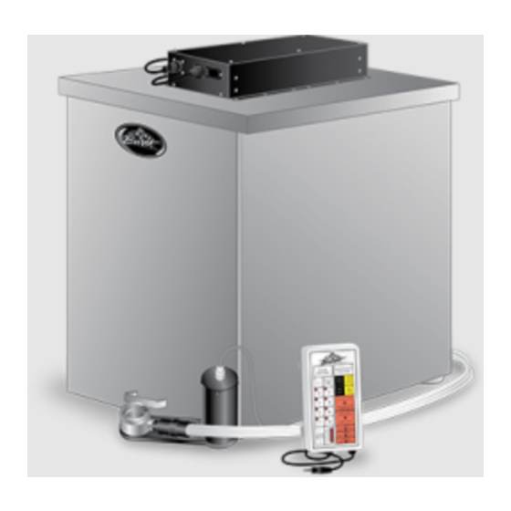
DO NOT operate the system unless it is properly grounded. Failure to follow this The FB 80D series system is an add-on to a instruction may result in electrocution. soft serve freezer designed to inject concentrated flavorings throughout soft serve product as it is dispensed. - Page 3 DO NOT install the unit in an area where a water jet could be used, and do not use a water jet to clean or rinse the system. Failure to follow these instructions may result in serious electrical shock. NOISE LEVEL: Airborne noise emission does not exceed 70 dB(A) when measured at a distance of 1.0 meter from the surface of the machine and at a height of 1.6 meters from the...
-
Page 4: Parts Identification/Function
FUNCTION ELE 430-RE-1 SPIGOT SWITCH ASSEMBLY Activates Injector Assembly. ELE 550 KEYPAD ASSEMBLY Flavor Burst unit command center. MIS 3109 KEYPAD BRACKET ASSEMBLY Mounts the keypad to the freezer. Attaches Injector Assembly to freezer ADPT 101A INJECTOR ADAPTER W/ O-RINGS door. - Page 5 General System Overview 26000 Figure 1...
- Page 6 Allows access to pumps. FAS 2024 8-32 X 1/4" PAN HEAD SCREWS Secures back panel to base. CAB 235R CABINET RIGHT SIDE PANEL Covers right side of inner cabinet. MIS 3150 FLAVOR BURST LOGO DECAL Displays Flavor Burst trademark logo.
- Page 7 Outer Cabinet 26001 Figure 2...
- Page 8 Inner Cabinet (See Figure 3) ITEM PART NO. DESCRIPTION QTY. FUNCTION CAB 201 SYRUP RACK COVER PANEL Keeps side and inner panels stable. CAB 204L SYRUP RACK LEFT PANEL Holds outer syrup rails. SYRUP BAG CONNECTOR Transports syrup from the bag to the SYR 944 ASSEMBLY pumps.
- Page 9 Inner Cabinet 26002 11 12 Figure 3...
- Page 10 Injector Assembly and Related Parts (See Figure 4) ITEM PART NO. DESCRIPTION QTY. FUNCTION Attaches Injector Assembly to freezer ADPT 101A INJECTOR ADAPTER W/ O-RINGS door. Creates tension to secure Adapter to RUB 642 ADAPTER O-RING freezer door. RUB 640 FLAT ADAPTER GASKET Provides sealed cavity inside Adapter.
- Page 11 Injector Assembly and Related Parts (Continued) ITEM PART NO. DESCRIPTION QTY. FUNCTION INJ 323 INJECTOR ASSEMBLY - NO HEAD Powers Injector system. Supplies power to Motor which turns INJ 330 INJECTOR MOTOR ASSEMBLY gears. Gears turn Gear Cartridge for even syrup INJ 331 INJECTOR GEARBOX ASSEMBLY distribution.
- Page 12 Syrup Pump and Related Parts (See Figure 5) ITEM PART NO. DESCRIPTION QTY. FUNCTION Pumps syrup from flavor bags to flavor SOFT SERVE SYRUP PUMP lines. Pumps syrup from flavor bags to flavor SYR 307 PERISTALTIC SYRUP PUMP 1 ea. lines.
- Page 13 Syrup Pump and Related Parts 26004 Figure 5...
- Page 14 Sanitizer Pump and Related Parts (See Figure 6) ITEM PART NO. DESCRIPTION QTY. FUNCTION SAN 748 SANITIZER PUMP ASSEMBLY Supplies sanitizer to flush tube. TUB 807 SANITIZER TUBE REPLACEMENT Transports sanitizer through pump. MIS 3013 FLAVOR LINE DUST CAP Cover to protect end of flavor lines. Provides tension in syrup line to affix to FAS 2051 ROLLED FLANGE EYELET...
- Page 15 Sanitizer Pump and Related Parts 26005 Figure 6...
- Page 16 Remote Module and Electronic Parts (See Figure 7) ITEM PART NO. DESCRIPTION QTY. FUNCTION ELE 550 KEYPAD ASSEMBLY Flavor Burst unit command center. ELE 430-RE-1 SPIGOT SWITCH ASSEMBLY Activates Injector Assembly. Supplies power to motor which turns INJ 330 INJECTOR MOTOR ASSEMBLY gears.
- Page 17 Remote Module and Electronic Parts 26006 (REVERSE SIDE) Figure 7...
- Page 18 Maintenance Kit and Spare Parts Kit (See Figure 8) ITEM PART NO. DESCRIPTION QTY. FUNCTION MIS 3160 MAINTENANCE KIT Cleans Flavor Burst components. DETAIL BRUSH – 005162* Cleans small ports and openings. 0.0625" X 0.5" X 4" SMALL BRUSH - 033059 Cleans smaller openings and parts.
- Page 19 Maintenance Kit and Spare Parts Kit 26007 Figure 8...
-
Page 21: Daily Opening Procedures
3. Remove each part from the sanitizer DAILY OPENING PROCEDURES solution. Place the items on a sanitary tray to air dry. (See Figure 10.) NOTE: YOUR HANDS SHOULD BE CLEANED AND SANITIZED BEFORE YOU PERFORM 26093 THE FOLLOWING PROCEDURES. NOTE: THE FOLLOWING PROCEDURES REQUIRE APPROVED, SERVICEABLE AND SANITIZED TOOLS AND BRUSHES. - Page 22 6. The following do not need to be sanitized on 2. Install the Injector Head onto the Drive a daily basis as part of the daily opening Assembly Gear Box and rotate off-center to procedures. However, inspect these areas secure. (See Figure 15.) and if necessary, clean according to instructions in the SCHEDULED 26024...
- Page 23 These steps do not necessarily need to be 26084 performed as part of the daily opening procedures. The following is a list of areas to ® check on the Flavor Burst system during opening procedures. These areas should be checked and adjusted if necessary. LEVEL 1.
-
Page 25: Daily Closing Procedures
2. Rotate the 9-Tube Assembly coupler until it DAILY CLOSING PROCEDURES unlocks and is able to slide out of the Injector Head syrup line opening. (See NOTE: YOUR HANDS SHOULD BE CLEANED Figure 23.) AND SANITIZED BEFORE YOU PERFORM THE FOLLOWING PROCEDURES. 26050 NOTE: THE FOLLOWING PROCEDURES REQUIRE APPROVED, SERVICEABLE AND... - Page 26 5. Lift the Suspension Bracket with the Injector 3. Rotate the Injector Head to unlock it from Assembly from the freezer door knob. (See the Gear Box. (See Figure 29.) Figure 26.) 26031 26052 Figure 29 Figure 26 4. Remove the Gear Cartridge from the Gear Box.
- Page 27 3. Brush and clean all exposed surfaces of the NOTE: DO NOT OPEN OR DISASSEMBLE Gear Cartridge with detergent water, then THE DRIVE ASSEMBLY GEAR BOX. rinse thoroughly. (See Figure 32.) 6. Place the Gear Box, Suspension Bracket, Gear Cartridge, and Injector Head in approved sanitizer solution and soak for at least 1 minute.
- Page 28 9. Replace the cap and hang the Assembly on 11. The following do not need to be sanitized on the Accessory Hanging Bracket. (See a daily basis. However, inspect these areas Figure 38.) and if necessary, clean according to instructions in the SCHEDULED MAINTENANCE section: (See Figure 40.) 26186 •...
-
Page 29: Replacing The Syrup Flavors
3. Pull the tray forward and remove the syrup REPLACING THE SYRUP FLAVORS bag. Discard the syrup bag if it is empty or expired. If the bag has usable syrup, store NOTE: BE SURE TO PLACE A CONTAINER the syrup as directed on the label. (See UNDER THE INJECTOR HEAD TO CATCH Figure 41.) THE PRODUCT AND SANITIZER SOLUTION. - Page 30 6. Lifting up with the bag fitment, press the 9. Make sure the syrup bag is settled neatly center pin of the bag fitment valve and into the tray, and then install the loaded tray gently press on the bag to release any into the cabinet.
- Page 31 12. Attach the Syrup Bag Adapter to the bag 15. Select and touch the number corresponding fitment. (See Figure 50.) with the new syrup flavor to prime the pump. 16. Place a container under the Injector Head to 26071 catch residual sanitizer solution and/or fresh product to be dispensed and press WATER / SYRUP FLUSH to prime the syrup line.
-
Page 33: Scheduled Maintenance
2. Rotate the 9-Tube Assembly coupler until it SCHEDULED MAINTENANCE unlocks and remove it from the Injector Head syrup line opening. (See Figure 55.) The following procedures are performed less frequently than daily or as needed. 26050 NOTE: YOUR HANDS SHOULD BE CLEANED AND SANITIZED BEFORE YOU PERFORM THE FOLLOWING PROCEDURES. - Page 34 5. Place the end of the 9-Tube Assembly into CIP - Phase 2: Syrup System Cleaning a container to catch the expelled syrup and sanitizer solution during the Clean-In-Place NOTE: THE FOLLOWING CLEAN-IN-PLACE procedure. (See Figure 58.) PROCEDURE (STEPS 8-22) SHOULD BE COMPLETED CONSECUTIVELY, BEGINNING WITH SYRUP LINE #1 (I.E.
- Page 35 10. Brush and clean the Syrup Bag Adapter 13. Brush and clean the outer surfaces of the thoroughly with detergent water. Then rinse syrup bag fitment and the Connector with thoroughly with clean water. (See detergent water, and a single service towel. Figure 63.) Then rinse and dry the parts using clean water and single service towels.
- Page 36 16. Connect the Pump Flush nozzle to the 20. Once the Pump Flush process has Syrup Bag Connector. (See Figure 69.) completed, disconnect the Pump Flush nozzle from the Syrup Bag Connector. (See Figure 70.) 26272 26273 Figure 69 17. Touch the number on the Keypad (1-8) of Figure 70 the corresponding syrup line and pump you wish to flush.
- Page 37 CIP - Phase 3: Reassembly 26. Remove the Syrup Line Manifold, Manifold cap, the Duckbill Check Valve, and Coupler 23. Connect each Syrup Bag Adapter to the Body from the sanitizer solution and place syrup bag fitments. (See Figure 72.) on a sanitary tray to air dry.
- Page 38 29. Carefully align the pins of the Syrup Line 33. Perform the “Assembling the Injector Manifold with the Syrup Line Connector and Assembly” and “Installing the Injector insert the end of the 9-Tube Assembly fully System” sections of the DAILY OPENING into the Coupler.
- Page 39 5. When no additional syrup lines remain, 3. Remove the Sanitizer Tank from the press the WATER / SYRUP FLUSH key to cabinet. (See Figure 84.) clean the Injector Head to complete the procedure. (See Figure 82.) 26241 26250 Figure 84 4.
- Page 40 6. Fill the Sanitizer Tank with approved Cleaning the Spout Adapter sanitizer. (See Figure 87.) The Spout Adapter does not require daily cleaning under normal operating conditions. Since the fitting is very tight, install the Adapter with the freezer door removed. Therefore, clean only as needed or when disassembling the freezer door for cleaning (approximately every 2 weeks).
- Page 41 4. Clean the two o-rings, the white gasket and 7. Lube the black o-rings and install them with the Spout Adapter with a small brush and the white gasket in their respective positions detergent water, and rinse thoroughly. (See on the Spout Adapter. (See Figure 95.) Figure 92.) Figure 95 Figure 92...
- Page 42 2. Remove the worn o-rings from the Injector 5. Remove the o-rings and Injector Head and Head. A small tool may be needed to place them on a sanitary tray to dry. (See remove the o-rings in the syrup port Figure 100.) opening.
- Page 43 Miscellaneous Cleaning Procedures Inside of the Cabinet The following parts of the FB 80D do not 26144 CLEAN require daily cleaning. Inspect these areas periodically and clean if necessary according to Detergent instructions. RINSE Mix approved detergent with warm water Water according to manufacturer’s instructions.
- Page 44 Keypad Mounting Bracket Injector Assembly Suspension Bracket Figure 105 Figure 106 1. Loosen the Mounting Bracket hand screws 1. Remove the Bracket from the Injector and remove the main plate. Assembly and disassemble it. 2. Clean both the main plate and the plate 2.
- Page 45 Accessory Hanging Bracket and 9-Tube Spigot Switch and Switch Bracket Assembly Casing ELECTRICAL HAZARD: DO NOT IMMERSE OR USE AN EXCESSIVE AMOUNT OF WATER OR DETERGENT IN CLEANING THE SPIGOT SWITCH ASSEMBLY. FAILURE TO COMPLY MAY RESULT IN SERIOUS ELECTRICAL SHOCK. Figure 107 1.
- Page 46 4. Repeat Steps 15-18 of the Clean-In-Place Procedure without sanitizer solution in the ® If you will not be using your Flavor Burst tank until the syrup lines are empty of system during the off-season or other extended sanitizer solution. Then perform Steps 20 periods of time, you should winterize the FB and 21 (skip Step 19).
-
Page 47: Equipment Setup
1. Ensure that the Spout Adapter has been EQUIPMENT SETUP sanitized according to instructions in the SCHEDULED MAINTENANCE section. NOTE: YOUR HANDS SHOULD BE CLEANED Then lube and install the white gasket and AND SANITIZED BEFORE YOU PERFORM both o-rings in their proper places inside THE FOLLOWING PROCEDURES. - Page 48 THAT FREEZER OR SIMILAR MODELS. (See Figure 118.) Figure 116 ® To activate the Flavor Burst system, a switch must be installed on the freezer draw-handle. Every FB 80D system ships with a standard Spigot Switch Assembly common to most freezers with flat handle bars.
- Page 49 2. Determine the approximate area and side of 5. Fully insert the Keypad stereo plug into the the freezer to attach the Bracket that will Spigot Switch jack and ensure that the best suit your needs. Typically this is the connection is fully engaged.
- Page 50 Connecting the Unit Syrup Line 4. Tighten the coupler nut and the casing to secure. (See Figure 127.) The syrup lines attached at the lower back of the cabinet connect the 8 bags of syrup to the Injector Assembly, with the 9 tube connecting the Sanitizer Tank to the Injector Assembly.
- Page 51 7. Return the Cabinet panel to the back of the 3. Remove the Sanitizer Tank from the unit and secure with the screw. (See cabinet. (See Figure 132.) Figure 130.) 26249 Figure 132 Figure 130 4. Set the Sanitizer Tank upright and remove the cap.
- Page 52 6. Reinstall the cap and tighten sufficiently. 3. Remove each part from the sanitizer Slide the Sanitizer Tank into the cabinet. solution. Place the items on a sanitary tray (See Figure 135.) to air dry. (See Figure 138.) 26252 26093 Figure 138 Figure 135 4.
- Page 53 Assembling the Injector Assembly Installing the Injector System and Suspension Bracket 1. Place the Gear Cartridge into the Drive Assembly Gear Box so that the gear teeth The Suspension Bracket helps stabilize the line up with the gear inside the Drive Injector Assembly on the freezer.
- Page 54 2. Assemble the Suspension Bracket and 3. Hang the Suspension Bracket on the lower install it onto the Gear Box on the side door post and install the Injector Assembly closest to the operator. Ensure all parts are on the preferred side of the freezer. Install assembled in the proper position.
- Page 55 6. Tighten the thumb nut and thumb screw to 3. Thoroughly clean, rinse and dry the area secure the Suspension Bracket. where the Casing will be mounted using detergent water, clean water, and single service towels. (See Figure 151.) NOTE: THE SUSPENSION BRACKET SHOULD BE POSITIONED ON THE DRIVE ASSEMBLY GEAR BOX DURING INITIAL 26160...
- Page 56 6. Place the 9-Tube Assembly, the Keypad 3. Clean, rinse and dry thoroughly the area on Cable, and the Motor Cable inside the which the Bracket will be mounted using Casing. (See Figure 154.) detergent water, clean water, and single service towels.
- Page 57 6. The 9-Tube Assembly slides into the 1. Ensure the power-switch is in the “off” smaller slot on the Bracket so that the position. Connect the Rotor Cable and the coupler casing is above the bracket and the Keypad Cable to the appropriate fitments syrup tubes hang below.
- Page 58 4. Connect the other end of the Pump Cable to NOTE: THE ON/OFF SWITCH ON THE the round outlet on the other side of the ELECTRONICS BOARD IS NOT FUNCTIONAL Module and tighten the connector ring to ON THIS MODEL AND HAS NO EFFECT ON secure.
- Page 59 Installing Flavors and Priming Syrup Lines 4. Lifting up with the bag fitment, press the center pin of the bag fitment valve and Each flavor for the FB 80D system is stored gently press on the bag to release any inside a numbered syrup tray within the system excess air.
- Page 60 8. Make sure the syrup bag is settled neatly 11. Attach the Syrup Bag Adapter to the bag into the tray, and then install the loaded tray fitment. (See Figure 176.) into the cabinet. (See Figure 173.) 26071 26196 Figure 176 Figure 173 12.
- Page 61 15. Place a container under the Injector Head to catch sanitizer solution and/or fresh product to be dispensed and press WATER / SYRUP FLUSH to prime the syrup line. (See Figure 178.) 26251 Figure 178 16. Once syrup flows consistently from the Injector Head, press CANCEL ENTRY.
-
Page 63: Keypad Operations
WATER / SYRUP FLUSH: Press and release KEYPAD OPERATONS to run sanitizer solution through the Injector Head. It is used to sanitize the Injector Head NOTE: YOUR HANDS SHOULD BE CLEANED and dispensing spout and also to purge the AND SANITIZED BEFORE YOU PERFORM area from any remaining product. - Page 64 TIMER: This key activates the Serving Time COMBO TIME ADJUSTMENT: This light Adjustment mode to program the system for indicates the COMBO TIMER key has been small, medium and large serving sizes. selected, entering the mode to adjust the length Adjustments to the serving size timing are also of time a flavor dispenses before switching to made in this mode.
- Page 65 COUNTER key to exit the mode. The This feature allows the operator to keep count resulting number is the number of servings ® of the servings of Flavor Burst products. The the unit has dispensed since the last time count is always accumulative such as the the counter has been reset (example: 6,253 odometer on an automobile.
- Page 66 ® Dispensing Flavor Burst Product 3. Release the Spigot Switch lever as you lift the draw-handle when the desired amount More than one flavor can be selected for a of product is drawn. (See Figure 188.) multi-flavored product. Simply select all the...
- Page 67 Adjusting the Flavor Level 3. Press “+” to increase the flavor concentration or “-” to decrease the ® To produce the best Flavor Burst serving, the concentration. The level is indicated by the flavor output must be adjusted to the proper illuminated bars on the graph.
- Page 68 6. To adjust all the flavors to the same level at 8. Press the SYRUP FLOW key to exit the once, do not select a specific flavor (skip mode and lock in the syrup levels. (See step 1) before pressing and holding the Figure 197.) SYRUP FLOW key for three seconds.
- Page 69 2. The number of illuminated bars in the graph 4. To decrease the timing (for more, narrower represent the length of time each layer is layers), press the “-” key until the correct dispensed. Use the following chart to number of bar graph lights are illuminated. determine the bar graph setting needed for (See Figure 201.) the desired dispense time for each flavor...
- Page 70 Setting Serving Size Timing 2. Press and hold the TIMER key for three seconds until the SERVING TIME The FB 80D keypad has a program functioned ADJUSTMENT light is illuminated. (See into the electronics that signals the operator to Figure 204.) cease drawing product at a preset time for each serving size (small, medium, and large).
- Page 71 4. Press the “+” key to increase the serving NOTE: WHEN A PARTICULAR SIZE IS size or press the “-” key to decrease the SELECTED, THE SYRUP PUMP WILL STOP size until the desired number of bar graph THE FLOW OF SYRUP AT THE SET TIME; lights are illuminated.
-
Page 78: Directory Of Cleaning Procedures
DIRECTORY OF CLEANING PROCEDURES The various cleaning and sanitizing procedures for the FB 80D are arranged in this manual according to when and how often the procedures need to be done. Use the following directory as a quick reference to all the cleaning procedures within this operations manual. DAILY OPENING PROCEDURES - page 20 •... -
Page 79: Parts Replacement Schedule
Spare Parts Kit for easy access. Every 3 Part No. Part Description Every 6 months Annually months ® FLAVOR BURST COMPONENTS Standard Spout Adapter with O-Rings Inspect and replace if ADPT 101A Minimum necessary and Gasket... -
Page 80: Recommended Maintenance Items Replacement Schedule
COMPANY. ALTERNATE PARTS AND KITS BY FREEZER MODEL Flavor Burst Company offers many equipment options and accessories through your local distributor that may be helpful for your operational or installation requirements. This includes adapter kits, adapters, brackets, and switches for various freezer models and manufacturers. Please contact your local distributor or visit us online at www.flavorburst.com... -
Page 81: Ordering/Service Information
2. Serial Number ____________________________________ 3. Voltage _________________________________________ 4. Maximum Fuse Size __________________________ Amps 5. Minimum Wire Ampacity _______________________ Amps Flavor Burst is a registered trademark of the Flavor Burst Company. Taylor is a registered trademark of the Taylor Company. All rights reserved.
Need help?
Do you have a question about the FB 80D Series and is the answer not in the manual?
Questions and answers