Table of Contents
Advertisement
Quick Links
Flavor Burst
®
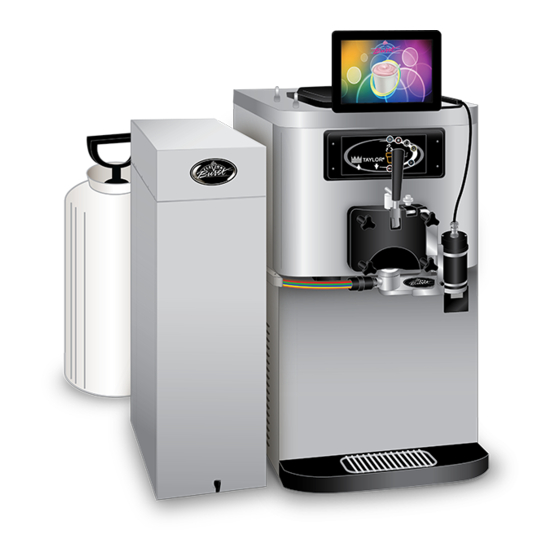
Premium Blended Beverage System
Model CTP 80CBB
Equipment, Maintenance and
Operations Manual
Manufactured by
Flavor Burst Company
499 Commerce Drive
Danville, IN 46122
For general information and to locate a
distributor near you, call or visit our website:
Phone: (317) 745-2952
Toll Free Number: (800) 264-3528
Fax: (317) 745-2377
www.flavorburst.com
For pricing, ordering and support,
contact one of our qualified distributors.
NOTE: THIS SYSTEM USES BLEND SYRUPS ONLY (FLA xxxBLD)
This system is NOT compatible with the standard beverage syrups (FLA xxxSH) as it cannot connect to
the standard beverage syrup fitments.
Warranty
An installation and warranty form is provided with every CTP 80CBB system, located inside the
80CBB unit with this manual. It is important that the operator carefully review the warranty and
installation documents accompanying the unit before using this system. Any questions or concerns
regarding the warranty should be clarified upon delivery or installation. For more information, contact
your local authorized Flavor Burst
©2021 Flavor Burst Company
All Rights Reserved
®
distributor.
Printed in March
CTP
Printed in
The United States of America
Advertisement
Table of Contents

Related Manuals for Flavor Burst CTP 80CBB


Summary of Contents for Flavor Burst CTP 80CBB
- Page 1 Warranty An installation and warranty form is provided with every CTP 80CBB system, located inside the 80CBB unit with this manual. It is important that the operator carefully review the warranty and installation documents accompanying the unit before using this system. Any questions or concerns regarding the warranty should be clarified upon delivery or installation.
-
Page 2: Table Of Contents
TABLE OF CONTENTS FCC Conformity Statement..…...………………………………………….………………...3 Introduction……………………………...………………………………………….………….4 Safety Precautions……………………………..…………….………..……..….…………..4 Environmental Notices………………...………………………………………….………….5 Parts Identification/Function……...……………………….……..…..……….……..….…..7 Daily Opening Procedures……..………………………….…….…..…….………..……...26 Sanitizing the Blending System………………………….….………………..…...…26 Assembling the Blending Assembly………………...…..………………………...…27 Installing the Blending System………………………………….……….……...…...28 Other items to check during opening procedures……………………………….…29 Daily Closing Procedures………………………………………….……………….………30 Removing the Blending System………………………………..……………...…...30 Disassembling the Blending Assembly………………..……………………….……31 Sanitizing the Blending System…………………………………..……………...…..31 Replacing the Syrup Flavors…………...…………………………..…….………...……...34... - Page 3 Power Connections and Power Up……………………………………….…..…66 Installing Flavors and Priming Syrup Lines………………………...……….…...…67 Color Touch Panel Overview.…….………………..…………………………..……...…70 Quick Reference Guide for Color Touch Panel Setup..…..……...…….………….70 Testing the CTP 80CBB System………..…….……………………..…...…..…...71 Directory of Cleaning Procedures……………………………...………………..…….….76 Parts Replacement Schedule………...………………….………………..….……………77 Recommended Maintenance Items Replacement Schedule………………..…..…78 Alternate Parts and Kits by Freezer Model……………………………...……...…..….78...
-
Page 4: Fcc Conformity Statement
FCC Conformity Statement: This device complies with Part 15 of the FCC Rules. Operation is subject to the following two conditions: (1) this device may not cause harmful interference, and (2) this device must accept any interference received, including interference that may cause undesired operation. Changes or modifications not expressly approved by the party responsible for compliance could void the user's authority to operate the equipment. -
Page 5: Introduction
Failure to follow this instruction may result in electrocution. The CTP 80CBB series system is added to a frozen beverage freezer to blend concentrated DO NOT operate the system with larger flavorings throughout frozen beverage product fuses than specified on the system data label. -
Page 6: Environmental Notices
Fahrenheit. Unit should never be change. Contact your local distributor for most exposed to freezing temperatures. recent updates concerning the CTP 80CBB unit. ENVIRONMENTAL NOTICES If the crossed out wheeled bin symbol is affixed to this product, it signifies that this product is compliant with the EU Directive for Waste Electric/Electronic Goods (WEEE) as well as other similar legislation in affect after August 13, 2005. - Page 7 PAGE INTENTIONALLY LEFT BLANK...
-
Page 8: Parts Identification/Function
General System Overview (See Figure 1) ITEM PART NO. DESCRIPTION QTY. FUNCTION TOUCH PANEL ASSEMBLY WITH ELE 906A Flavor Burst unit command center. BRACKET ELE 434 POWER CABLE Supplies the electronics board with power. INJ 424P PREMIUM BLENDING ASSEMBLY Blends syrups into the product. - Page 9 General System Overview Figure 1...
- Page 10 Cabinet – (See Figure 2) ITEM PART NO. DESCRIPTION QTY. FUNCTION ELECTRONICS SYSTEM Control system for the unit. CAB 135R-A RIGHT SIDE PANEL Holds tray support brackets and panel brackets. CAB 145 TRAY SUPPORT BRACKET Supports flavoring trays. Fastens panel brackets to divider panel, secures FAS 2024 8-32 X 1/4 PAN HEAD sides.
- Page 11 Cabinet (Continued) ITEM PART NO. DESCRIPTION QTY. FUNCTION Provides spacing between cabinet base and RUB 618 RUBBER BUMPER WITH WASHER table. Attaches to screw and holds rubber bumper FAS 2035 8-32 NUTS - EXT. LOCK WASHER in place. MIS 3074 SHORTY PLUG #1672 Covers screw hole in rubber bumper.
- Page 12 Premium Blending Assembly and Related Parts (See Figure 3) ITEM PART NO. DESCRIPTION QTY. FUNCTION PREMIUM BLENDING ASSEMBLY INJ 424P WITH SYRUP LINES, ADAPTER, & Transports and blends syrup into product. BRACKET Connects flavor line to inject syrups into INJ 422C BLENDING HEAD ASSEMBLY product.
- Page 13 Premium Blending Assembly and Related Parts (Continued) ITEM PART NO. DESCRIPTION QTY. FUNCTION BLENDING ASSEMBLY - NO INJ 323TS Powers Blending system. HEAD HIGH SPEED BLENDING 10A INJ 330HSB 1 ea. Supplies power to Motor which turns gears. MOTOR ASSEMBLY BLENDING GEARBOX Gears turn Gear Cartridge for even syrup 10B INJ 331...
- Page 14 PAGE INTENTIONALLY LEFT BLANK...
- Page 15 Premium Blending Assembly and Related Parts Figure 3...
- Page 16 Syrup Pump and Related Parts (See Figure 4) ITEM PART NO. DESCRIPTION QTY. FUNCTION Pumps syrup from flavor bags to flavor SOFT SERVE SYRUP PUMP lines. PERISTALTIC SYRUP PUMP – Pumps syrup from flavor bags to flavor SYR 926P 1 ea. PREMIUM BEVERAGE lines.
- Page 17 Syrup Pump and Related Parts Figure 4...
- Page 18 CLEAR TUBING Transports sanitizer to Pump Flush Adapter. Holds sanitizer solution and delivers it to the SAN 740 SANITIZER TANK ASSEMBLY Flavor Burst cabinet and Blending Assembly. 12A SAN 701 SANITIZER TANK 1 ea. Holds sanitizer solution. HAND PUMP ASSEMBLY-FLUTED 12B SAN 734 1 ea.
- Page 19 Sanitizer Pump and Related Parts Figure 5...
- Page 20 8-32 X 1/2" PAN HEAD Secures various parts within the top of unit. MIS 3150 FLAVOR BURST LOGO DECALS Displays Flavor Burst trademark logo. CAB 156 CONNECTOR SHIELD Protects power cables from liquids. Provides a power connection to the outside ELE 485CTP 120V POWER ENTRANCE MODULE of the cabinet.
- Page 21 Electronic Parts and Connections (Continued) ITEM PART NO. DESCRIPTION QTY. FUNCTION Connects the external rotor cable to the ELE 930 INTERNAL ROTOR CABLE electronics board. FAS 2008 4-40 X 3/8" PAN HEAD SCREW Attaches the ethernet plate to the panel. MIS 3216 CLOSURE PLUG 5/8 INCH Closes up extra opening in the base panel.
- Page 22 PAGE INTENTIONALLY LEFT BLANK...
- Page 23 Electronic Parts and Connections Figure 6...
- Page 24 Spare Parts Kit (See Figure 7) ITEM PART NO. DESCRIPTION QTY. FUNCTION SPARE PARTS KIT – PREMIUM SPR 5800P Houses extra spare parts and wear items. BEVERAGE DRAW SWITCH ASSEMBLY WITH Activates Blending Assembly through ELE 510 BRACKET frozen beverage freezer. Provides sealed cavity and prevents syrup RUB 601 9-POS DUCKBILL CHECK VALVE...
- Page 25 Spare Parts Kit Figure 7...
- Page 26 PAGE INTENTIONALLY LEFT BLANK...
-
Page 27: Daily Opening Procedures
3. Remove each part from the sanitizer DAILY OPENING PROCEDURES solution. Place the items on a sanitary tray to air dry. NOTE: YOUR HANDS SHOULD BE CLEANED AND SANITIZED BEFORE YOU PERFORM THE FOLLOWING PROCEDURES. NOTE: THE FOLLOWING PROCEDURES REQUIRE APPROVED, SERVICEABLE AND SANITIZED TOOLS AND BRUSHES. -
Page 28: Assembling The Blending Assembly
6. The following do not need to be sanitized on 2. Install the Blending Head onto the Drive a daily basis as part of the daily opening Assembly Gear Box and rotate off-center to procedures. However, inspect these areas secure. and if necessary, clean according to instructions in the SCHEDULED MAINTENANCE section:... -
Page 29: Installing The Blending System
Installing the Blending System 5. Ensure that the Blending Assembly is level horizontally and make any adjustments to 1. Ensure the o-rings are installed on the spout the suspension bracket as needed using the adapter. Snap the adapter onto the freezer adjustment hand knob. -
Page 30: Other Items To Check During Opening Procedures
These steps do not necessarily need to be performed as part of the daily opening procedures. The following is a list of areas to check on the Flavor Burst system during ® opening procedures. These areas should be checked and adjusted if necessary. -
Page 31: Daily Closing Procedures
2. Rotate the 9-Tube Assembly coupler until it DAILY CLOSING PROCEDURES unlocks and is able to slide out of the Blending Head syrup line opening. NOTE: YOUR HANDS SHOULD BE CLEANED 26050 AND SANITIZED BEFORE YOU PERFORM THE FOLLOWING PROCEDURES. NOTE: THE FOLLOWING PROCEDURES REQUIRE APPROVED, SERVICEABLE AND SANITIZED TOOLS AND BRUSHES. -
Page 32: Disassembling The Blending Assembly
6. Remove the spout adapter from the freezer Disassembling the Blending Assembly head. Since the fitting can be tight, you may need to use a small tool to pry the adapter 1. Rotate the Drive Motor to unlock and from the door spout. remove the Drive Motor from the Drive Assembly Gear Box. -
Page 33: Sanitizing The Blending System
Sanitizing the Blending System 5. When the Drive Assembly Gear Box has soaked for at least 5 minutes, brush and 1. Prepare detergent water by mixing several clean all exposed surfaces and openings drops of Dawn dish soap with a gallon of with warm detergent water and rinse ®... - Page 34 8. Remove each part from the sanitizer 12. Clean, rinse and dry the surfaces of the solution. Place the items on a sanitary tray Drive Motor and exposed surfaces of the to air dry. cabinet using warm detergent water, warm water (108°F / 42°C), and single service towels.
-
Page 35: Replacing The Syrup Flavors
PROPER PREPARATIONS OF THESE 5. Press and hold the center logo on the CLEANING AGENTS. Touch Panel to access the Flavor Burst Maintenance Menu. If the screen asks for a NOTE: INSPECT ALL WEAR ITEMS AND password, enter the password. - Page 36 7. Press the flavor of the line to be flushed and 10. Select the flavor you wish to use, then place follow the instructions outlined on the Touch the bag on the table with the fitment up and Panel screen to flush the syrup line. remove the dust cap.
- Page 37 14. Make sure the syrup bag is settled neatly 17. Using the spray bottle with the sanitizer into the tray, and then install the loaded tray solution, spray the syrup bag fitment and into the cabinet. the syrup bag connector. Allow these parts to sanitize for at least 5 minutes.
- Page 38 22. When the syrup flowing from the spout is thick and undiluted, press a flavor key again to stop the prime function. 23. Repeat Steps 21 and 22 to prime any other new syrup bags that have been installed. 24. When all the syrup lines with replaced flavors have been primed, go to “Flushing Functions”...
-
Page 39: Scheduled Maintenance
NOTE: OPERATE UNIT UNDER NORMAL AMBIENT TEMPERATURES BETWEEN 60 AND 80 DEGREES FAHRENHEIT. UNIT SHOULD NEVER BE EXPOSED TO NOTE: SOME FLAVOR BURST SYSTEMS FREEZING TEMPERATURES. HAVE A SMALLER SANITIZER TANK. IF YOUR TANK RUNS OUT OF SOLUTION Clean-In-Place (CIP) Procedure... - Page 40 4. Prepare detergent water by mixing several 8. Disconnect the syrup bag connectors from drops of Dawn dish soap with a gallon of all the syrup bags. ® warm water (108°F / 42°C). 5. Rotate the 9-Tube Assembly coupler until it unlocks and remove it from the Blending Head syrup line opening.
-
Page 41: Cip - Phase 2: Flush
11. Press and hold the center logo on the been flushed. While the lines are flushing, Touch Panel to access the Flavor Burst proceed to “Phase 3: Clean” to make the Maintenance Menu. If the screen asks for a most of your time. -
Page 42: Cip - Phase 3: Clean
CIP – Phase 3: Clean 19. Clean the exposed surfaces of the bag fitment and the syrup bag connector with 16. Brush and clean the Gear Box, Blending warm detergent water. Brush the bag Head, Gear Cartridge, spout adapter, syrup fitment with the medium brush and the line manifold, manifold cap, duckbill check Connector with the small brush. -
Page 43: Cip - Phase 4: Reassemble
CIP - Phase 4: Reassemble 25. Push the coupler nut into the coupler body and rotate the coupler body until motion 22. Reconnect the syrup lines and bags of stops to secure. syrup by pressing the syrup bag connector 26179 onto the bag fitment valve. -
Page 44: Refilling The Sanitizer Tank
FRESH sanitizer solution in the tank 1. Press and hold the center logo on the that is no more than 28 days old. Replace older Touch Panel to access the Flavor Burst Maintenance Menu. If the screen asks for a solution with fresh sanitizer solution. -
Page 45: Replacing Blending Head O-Rings
6. When all the syrup lines with replaced 4. Submerge the Blending Head and the new flavors have been primed, go to “Flushing replacement o-rings in sanitizer solution for Functions” in the Maintenance Menu and at least 5 minutes. press FLUSH SPOUT to clean the spout. 26250 Flush Spout 5. -
Page 46: Miscellaneous Cleaning Procedures
Miscellaneous Cleaning Procedures Inside of the Cabinet The following parts of the CTP 80BLD do not require daily cleaning. Inspect these areas periodically and clean if necessary according to instructions. Prepare detergent water by mixing several drops of Dawn® dish soap with a gallon of warm water (108°F / 42°C). -
Page 47: Blending Assembly Suspension Bracket
Blending Assembly Suspension Bracket Touch Panel and Mounting Bracket CLEAN 26145 Detergent RINSE Water SANITIZE 1. Remove the bracket from the Blending NOTE: DO NOT GET WATER NEAR THE Assembly and disassemble it. CABLE CONNECTIONS OR SPEAKER HOLES ON THE TOUCH PANEL. 2. -
Page 48: Winterizing The Unit
5. Empty the sanitizer tank and return the tank to the unit. ® If you will not be using your Flavor Burst system during the off-season or other extended periods of time, you should winterize the CTP 80CBB system as a precautionary practice to avoid damage or undesirable syrup build-up in the unit. - Page 49 9. Scroll down to the Maintenance Functions 12. Repeat Steps 10 and 11 for the second line, section and touch the key named “Flushing then the third, and so on until all the lines Functions”. have been cleared of sanitizer solution. 13.
- Page 50 PAGE INTENTIONALLY LEFT BLANK...
-
Page 51: Equipment Setup
EQUIPMENT SETUP Bracket NOTE: YOUR HANDS SHOULD BE CLEANED The Touch Panel is the control unit for the AND SANITIZED BEFORE YOU PERFORM Flavor Burst ® system. Normal operating THE FOLLOWING PROCEDURES. functions are performed using the Touch Panel and the freezer draw handle. The Touch Panel... - Page 52 4. Measure and mark with a pencil the center 7. Connect the ethernet cable to the “DRIVER of the freezer within that cleaned area. BOARD 1” ethernet port behind the Touch Measure and mark the center of the base Panel screen. plate of the mounting bracket assembly.
- Page 53 10. Insert the hex bolts through the Touch 13. To adjust the height or angle of the Touch Panel plate arms from the outside, through Panel, loosen the hex bolts and lock nuts the upright slots of the anchor bracket. and move the Touch Panel into the desired Secure the bolts with the lock nuts with the position.
-
Page 54: Draw Switch Options
The of the switch extension into the integrated CTP 80CBB system comes with a few switch switch port on the freezer. Connect the options and more are available from your other end of the extension to the switch port distributor. -
Page 55: Installing The Ele 510 Draw Switch Externally
This is approximately 1/8” above the draw pin. Flavor Burst highly recommends using an integrated switch to power the CTP 80CBB 26151 system (ELE 474-NCL for both shake and slush product). However, if no integrated... -
Page 56: Installing The Ele 510 Draw Switch Internally On A Taylor 428/432
Flavor Burst highly recommends integrated switches be installed to power the CTP 80CBB system. However, if no integrated switches are available at the time of installation, use the ELE 510 external switch included with this system. The ELE 510 can also be mounted inside the front panel of Taylor 428 and 432 models as directed below. - Page 57 3. Attach the switch assembly just left of the 6. Replace the front panel. Taylor internal switch, to the inside of the cover plate. The ELE 510 switch lever should be just above the internal draw pin as shown. 26096 7.
-
Page 58: Installing The Ele 700C Draw Handle Switch On A Taylor C708-Shake
Installing the ELE 700C Draw Handle Switch 4. Mount the ELE 700C draw handle switch on a Taylor C708-SHAKE Freezer over the draw handle so that the bracket holes line up with the pivot pin holes. The C708-SHAKE freezer includes a built-in switch port, just under the door. -
Page 59: Sanitizing The Blending System
Sanitizing the Blending System Assembling the Blending Assembly The two Blending Head o-rings and the Gear 1. Prepare sanitizer solution by mixing half a Cartridge are wear items and will need to be packet (1 oz) of Stera-Sheen® Green Label replaced periodically. -
Page 60: Installing The Spout Adapter
Installing the Spout Adapter Recommended Blending Assembly Mounting Positions Every CTP 80CBB system ships with a standard ADPT 104RA spout adapter common The suspension bracket helps stabilize the to most beverage freezers. Also included is an Blending Assembly on the freezer. When... -
Page 61: Installing The Blending Assembly On A Standard Beverage Freezer
(B) When possible, install the 9-Tube Assembly Installing the Blending Assembly on a on the side of the freezer with the INTAKE Standard Beverage Freezer vents, with the rest of the Blending Assembly on the opposite side. Typically, 1. Determine how the Blending Assembly will the intake vents are on the right side on be positioned on the freezer. -
Page 62: Installing The Blending Assembly On A C708-Shake Freezer
3. Hang the suspension bracket on the lower 7. Tighten the thumb nut and screws to secure door post and install the Blending Assembly the suspension bracket. on the preferred side of the freezer. Install NOTE: THE SUSPENSION BRACKET the Blending Head locking ring fully over the SHOULD BE POSITIONED ON THE GEAR spout adapter so that the locking collar BOX DURING INITIAL SET-UP AND DOES... - Page 63 3. Slide the bracket in between the freezer 6. Position the bracket so that it is in-line door and the freezer panel. vertically and horizontally and the Gear Box is level. Tighten the hinge knobs. Install the Gear Box thumb nut underneath the Gear Box, or use the nylon locking nut provided with the bracket assembly.
-
Page 64: Mounting The Tube / Cable Casing Assembly
Mounting the 9-Tube / Cable Casing 3. Swing the casing cover outward. Assembly 26463 The CTP 80CBB includes a metal cable casing assembly to house and hold the 9-Tube Assembly level with the Blending Assembly. Other cables, such as the ethernet cable, can also be hidden in this assembly, or the plastic one as explained in the next section. -
Page 65: Mounting The Plastic Casing Assembly
The tank system delivers solution to ® the opposite side of the 9-Tube Assembly tubes specific areas of the Flavor Burst system such and metal casing, a smaller plastic Touch Panel as the Blending Head and syrup lines during cable casing is included to hide those cables. -
Page 66: Connecting The Unit Syrup Line
4. Reinstall the hand pump and tighten 3. Connect the 9-Tube Lead with the 9-Tube sufficiently. Assembly, with the 9-hole gasket in between. Align the 9-hole gasket with the coupler pins of the 9-Tube Lead and place the gasket against the coupler. Then align the coupler pins of the two tube assemblies and connect them. -
Page 67: Power Connections And Power Up
Power Connections and Power Up 4. Connect the power cord to the port on the back panel. The electrical connections for the CTP 80CBB 26222 are located on the upper back panel of the unit. Once the cables have been connected and the unit is turned on, it can remain on during normal daily operations. -
Page 68: Installing Flavors And Priming Syrup Lines
4. Lifting up with the bag fitment, press the center pin of the bag fitment valve and Each flavor for the CTP 80CBB system is gently press on the bag to release any stored inside a numbered syrup tray within the excess air. - Page 69 SCHEDULED MAINTENANCE section. The Clean-In- Place procedure MUST be done during the initial setup of the CTP 80CBB to ensure all the parts and syrup lines are sanitized and ready for use. 11. After the Clean-In-Place procedure, the syrup lines will be filled with sanitizer solution.
- Page 70 PAGE INTENTIONALLY LEFT BLANK...
-
Page 71: Color Touch Panel Overview
NOTE: THE “REGISTER EQUIPMENT” MENU even be programmed for different languages. MAY NOT BE FUNCTIONAL. The CTP 80CBB system is simple to use with 4. Under the section “Flushing and Priming the Touch Panel selection of flavors. More than Settings”, you can adjust how long it takes one flavor can be selected for each serving. -
Page 72: Testing The Ctp 80Cbb System
Testing the CTP 80CBB System 3. The next screen may show options to select a size. If so, make your selection. Once the system is enabled to dispense flavors, test each flavor to ensure they all dispense properly and that the Blending/Blending Assembly operates correctly. - Page 73 5. Make your flavor selections on the next 6. Hold a container under the spout to catch screen by touching the flavor button. Once flavor product. Pull the draw handle down a flavor is selected, the button moves to a to dispense product.
- Page 74 7. Evaluate your serving for both appearance 9. If the white cap option is enabled, see if and taste. Look and taste the serving to syrup product has cleared the Blending ensure the syrup level is acceptable. Draw Head. Make sure there is not too much servings of the other flavors to evaluate unflavored product at the top of your their syrup dispensing levels.
- Page 75 11. Make any other adjustments to settings in the Maintenance Menu settings as needed. 12. If a syrup line fails to operate when tested, select that flavor on the Touch Panel and draw the serving again to verify the syrup pump is malfunctioning.
- Page 76 PAGE INTENTIONALLY LEFT BLANK...
-
Page 77: Directory Of Cleaning Procedures
DIRECTORY OF CLEANING PROCEDURES The various cleaning and sanitizing procedures for the CTP 80CBB are arranged in this manual according to when and how often the procedures need to be done. Use the following directory as a quick reference to all the cleaning procedures within this operations manual. -
Page 78: Parts Replacement Schedule
The following schedule has been prepared as a reference for maintaining the wear items used with the CTP 80CBB system. Many factors affect the useful life of wear items including climate, store hours, store traffic, sales volumes, etc. Therefore, each operator must determine an appropriate schedule for his or her unique operation. -
Page 79: Recommended Maintenance Items Replacement Schedule
RECOMMENDED MAINTENANCE ITEMS REPLACEMENT SCHEDULE The following maintenance tools are recommended utensils for CTP 80CBB system cleaning procedures. These items are not included with the system but are available through your local Taylor Company distributor. Suitable alternatives for these Taylor maintenance items may be available through your distributor. -
Page 80: Ordering/Service Information
2. Serial Number ____________________________________ 3. Voltage _________________________________________ 4. Maximum Fuse Size __________________________ Amps 5. Minimum Wire Ampacity _______________________ Amps Flavor Burst is a registered trademark of the Flavor Burst Company. Taylor is a registered trademark of the Taylor Company. All rights reserved.
Need help?
Do you have a question about the CTP 80CBB and is the answer not in the manual?
Questions and answers