Table of Contents
Advertisement
Quick Links
®
Flavor Burst
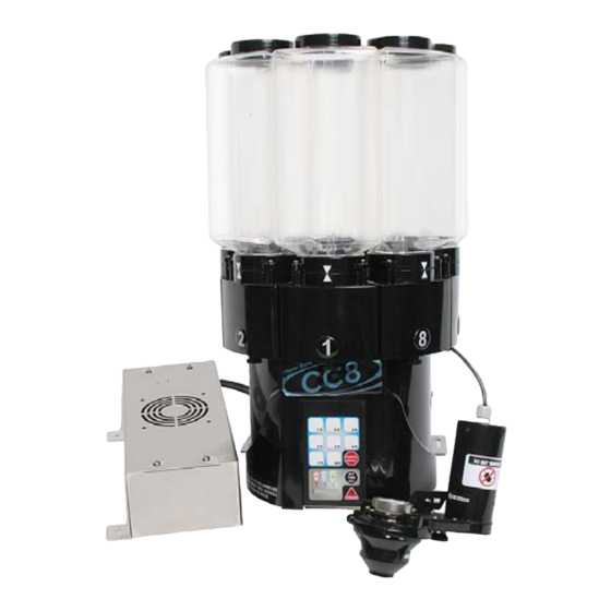
Frozen Beverage Unit
Model FB CC8S-08
Model FB CC8S-26
Flavor Burst Company
499 Commerce Drive
Danville, IN 46122
Phone: (317) 745-2952
Toll Free Number:
(800) 264-3528
Fax: (317) 745-2377
Table of Contents
Introduction...............................................................................................................1
Safety Precautions......................................................................................................1
Parts Identification/Function..........................................................................................2
Daily Opening Procedures..........................................................................................15
Daily Closing Procedures..........................................................................................19
Refilling the Containers............................................................................................23
Scheduled Maintenance.............................................................................................25
Equipment Setup......................................................................................................35
CLR 2000 Cooling Hood Assembly (Optional)..............................................................53
Keypad Operations...................................................................................................57
Helpful Suggestions for Successful Operations of the CC8...............................................63
Troubleshooting Guide..............................................................................................65
Directory of Cleaning Procedures................................................................................69
Parts Replacement Schedule......................................................................................70
Recommended Maintenance Items Replacement Schedule.............................................71
Alternate Parts and Kits by Freezer Model.....................................................................71
Ordering/Service Information......................................................................................72
Wiring Diagram........................................................................................................73
Warranty
An installation and warranty form is provided with every CC8S system, located inside the CC8S unit with this manual. It is
important that the operator carefully review the warranty and installation documents accompanying the unit before using this
system. Any questions or concerns regarding the warranty should be clarified upon delivery or installation. For more
information, contact your local authorized Flavor Burst distributor.
©2007 Flavor Burst Company
All Rights Reserved
Printed in August
Printed in
The United States of America
Advertisement
Table of Contents

Subscribe to Our Youtube Channel
Related Manuals for Flavor Burst FB CC8S-08


Summary of Contents for Flavor Burst FB CC8S-08
-
Page 1: Table Of Contents
Any questions or concerns regarding the warranty should be clarified upon delivery or installation. For more information, contact your local authorized Flavor Burst distributor. ©2007 Flavor Burst Company... -
Page 3: Introduction
DO NOT put objects or fingers in the door spout. Failure to follow this instruction may ® result in contaminated product or personal Flavor Burst ingredients are available in injury from blade contact. individually sealed bags and are stored in the refillable containers of the CC8S system. -
Page 4: Parts Identification/Function
PARTS IDENTIFICATION/FUNCTIONS General System Overview (See Figure 1) ITEM PART NO. DESCRIPTION QTY. FUNCTION STORES THE INGREDIENTS FOR THE CC8 CW 134-RA CW CONTAINER UNIT MODULE MOTOR HOUSING HOUSES THE CC8 MOTORS AND CW 175 AGITATORS ASSEMBLY HOUSES KEYPAD AND SUPPORTS CC8 CW 116 MOUNTING BASE - BLACK CONTAINERS AND MOTORS... - Page 5 General System Overview 27001 Figure 1...
- Page 6 Mounting Base Assembly (See Figure 2) ITEM PART NO. DESCRIPTION QTY. FUNCTION CW 144 32 OZ. WN FUNNEL FUNNELS INGREDIENTS INTO TUBE FASTENS CC8 CONNECTOR PLATE INTO FAS 2008 4-40 X 3/8" PAN HEAD PLACE CW 127 CW CONN. MOUNTING PLATE SECURES TOP PLUG OF TRI-CABLE CW 154 CC8 LOGO DECAL...
- Page 7 Mounting Base Assembly ITEM PART NO. DESCRIPTION QTY. FUNCTION CW KEYPAD ASSEMBLY 13 CW 194K CC8 UNIT COMMAND CENTER AUTO SIZE 13A CW 194 KEYPAD OVERLAY AUTO SIZE IDENTIFIES KEYPAD FUNCTIONS MOUNTING BASE COVER ENCLOSES BOTTOM OF CC8 AND 14 CW 142 PANEL SECURES TRI-CABLE WIRES TRANSFERS INGREDIENTS FROM THE...
- Page 8 Carousel Assembly (See Figure 3) ITEM PART NO. DESCRIPTION QTY. FUNCTION CW 134-RA CW CONTAINER ASSEMBLY STORES INGREDIENTS FOR THE CC8 PROVIDES EASY ACCESS FOR 1A CW 182 CW CONTAINER CAP 1 EACH REFILLING. 1B CW 134-R CW CONTAINER 1 EACH STORES INGREDIENTS FOR THE CC8 MODULE MOTOR HOUSING HOUSES THE CC8 MOTORS AND...
- Page 9 Carousel Assembly 27003 Figure 3...
- Page 10 Blending Assembly and Related Parts (See Figure 4) ITEM PART NO. DESCRIPTION QTY. FUNCTION TAYLOR BLENDER ADAPTER ATTACHES BLENDING ASSEMBLY TO ADPT 104R-A FREEZER DOOR WITH O-RINGS ADAPTER O-RING PARKER CREATES TENSION TO SECURE ADAPTER TO 1A RUB 627 FREEZER DOOR #2-120 BUNA TAYLOR BLENDER ADAPTER ATTACHES BLENDING ASSEMBLY TO...
- Page 11 Blending Assembly and Related Parts 27004 Figure 4...
- Page 12 Power Supply Box and Electronic Parts (See Figure 5) ITEM PART NO. DESCRIPTION QTY. FUNCTION POWER SUPPLY BOX ATTACHES POWER SUPPLY BOX TO THE MIS 3157-A FREEZER MOUNTING BRACKET ATTACHES THE POWER SUPPLY BOX TO 1A MIS 3157 MOUNTING BRACKET THE FREEZER ACCESSORY MOUNTING SECURES THE POWER SUPPLY BOX TO...
- Page 13 Power Supply Box and Electronic Parts 27005 (REVERSE SIDE) Figure 5...
- Page 14 Spare Parts Kit and Spare Parts (See Figure 6) ITEM PART NO. DESCRIPTION QTY. FUNCTION SPR CC8S CC8S SPARE PARTS KIT HOUSES CC8S SPARE PARTS CARRIES INGREDIENTS FROM CW 111-A-24 HOPPER TUBE ASSEMBLY CONTAINERS TO BLENDING ASSEMBLY HOUSES BLENDING AUGER AND CW 109 BLENDING HOPPER - BLACK PROVIDES MIXING AREA...
- Page 15 Spare Parts Kit and Spare Parts 27006 ADPT 104R-A Seal & O-Rings RUB 627 RUB 632 RUB 652-R RUB 654-R Figure 6...
- Page 16 Cooling Hood Assembly - Optional (See Figure 7) ITEM PART NO. DESCRIPTION QTY. FUNCTION CONTAINS THE COOL AIR PRODUCED BY CLR 151 COOLING HOOD THE COOLING FAN ATTACHES THE COOLING HOOD TO THE CLR 100 BASE RING CAROUSEL ASSEMBLY 10-32 x 5/8 x 1 1/2" THUMB HOLDS THE BASE RING TOGETHER AND FAS 2091 ALLOWS IT TO OPEN AND CLOSE...
-
Page 17: Daily Opening Procedures
Sanitizing the Blending System DAILY OPENING PROCEDURES 1. Prepare approved sanitizer solution NOTE: YOUR HANDS SHOULD BE CLEANED according to manufacturer’s instructions. AND SANITIZED BEFORE YOU PERFORM THE FOLLOWING PROCEDURES. 2. Place the Gear Box with suspension bracket, Blending Auger, Auger seal NOTE: INSPECT ALL WEAR ITEMS AND Blending Hopper, Blending Hopper plug, REPLACE IF NECESSARY. - Page 18 4. The following do not need to be sanitized on Install the Hopper onto the Blending a daily basis as part of the daily opening Assembly. Turn the Hopper clockwise until procedures. However, inspect these areas motion stops. (See Figure 11.) and, if necessary, clean according to instructions in the SCHEDULED 27013...
- Page 19 Installing the Blending System 3. Ensure that the Blending Assembly is level horizontally and make any adjustments 1. Suspend the Blending Assembly needed to the Suspension Bracket using the Suspension Bracket from one of the lower adjustment hand screw. (See Figure 16.) freezer door hand nuts.
- Page 20 Other Items To Check During Opening Procedures These steps do not necessarily need to be performed as part of the daily opening procedures. The following is a list of areas to check on the CC8S system during opening procedures. These areas should be checked and adjusted if necessary.
-
Page 21: Daily Closing Procedures
2. Lift the suspension bracket and remove the DAILY CLOSING PROCEDURES Blending Assembly from the freezer door nut. (See Figure 19.) NOTE: YOUR HANDS SHOULD BE CLEANED 27031 AND SANITIZED BEFORE YOU PERFORM THE FOLLOWING PROCEDURES. NOTE: INSPECT ALL WEAR ITEMS AND REPLACE IF NECESSARY. - Page 22 2. Slide the Drive Motor onto the Accessory 6. Remove the Blending Hopper plug from the Hanging Bracket. (See Figure 22.) Hopper opening. Rotate and remove the syrup port plug from the Blending Head and set all parts aside for cleaning. (See Figure 26.) Figure 22 3.
- Page 23 3. Brush and clean all exposed surfaces of the NOTE: UNDER NORMAL OPERATING Blending Auger, Auger seal, Blending CONDITIONS, IT IS NOT RECOMMENDED Hopper, and plugs with detergent water TO BRUSH OTHER AREAS INSIDE THE and then rinse thoroughly. (See Figure 28.) DRIVE ASSEMBLY GEAR BOX.
- Page 24 8. Turn the power switch off on the Power Supply Box. Then clean, rinse and dry the surfaces of the Drive Motor and the Keypad using detergent water, clean water, and single service towels. (See Figure 33.) 27046 CLEAN Detergent RINSE Water Figure 33...
-
Page 25: Refilling The Containers
2. If you are simply adding more of the same REFILLING THE CONTAINERS ingredient to the container and the parts do not require cleaning, remove the cap from NOTE: YOUR HANDS SHOULD BE CLEANED the container that requires refilling. (See AND SANITIZED BEFORE YOU PERFORM Figure 34.) THE FOLLOWING PROCEDURES. - Page 26 5. Holding a container under the dispensing spout, press the Keypad number of the dispensing module with the replaced ingredient product. Draw a serving to ensure the product is dispensing correctly. (See Figure 37.) 27183 Figure 37 6. Repeat the entire process for each container that needs to be filled.
-
Page 27: Scheduled Maintenance
2. Remove the Freezer Spout Adapter from SCHEDULED MAINTENANCE the freezer head. Since the fitting is very tight, you may need to use a small tool to The following procedures are performed less pry the Adapter from the door spout. (See frequently than daily, as needed or as Figure 38.) instructed. - Page 28 5. Place the o-rings and Freezer Spout 9. Set the Adapter on a flat, clean surface, and Adapter in sanitizer solution and soak for at then place the freezer door spout upright least 1 minute. (See Figure 41.) onto the Adapter. Rock the freezer door forward to snap the Adapter into place.
- Page 29 3. Carefully remove the module and container 6. Empty the remaining ingredients from the from the Carousel and hold the container container and store them according to upside-down so that the ingredients fall to instructions on the label if the product is the bottom.
- Page 30 9. Set the container and cap on a sanitary tray 3. Remove the retainer cap and the agitator to air dry. (See Figure 52.) from the motor shaft. (See Figure 53.) 27090 Figure 52 Figure 53 NOTE: ENSURE ALL PARTS ARE 4.
- Page 31 7. Place the items in sanitizer solution and 10. Using a spray bottle, spray the Impeller allow them to soak for at least 1 minute. Chamber with sanitizer solution and allow it (See Figure 57.) to soak for at least 1 minute. Allow the chamber to air dry.
- Page 32 14. Line up the positioning ridge of the Cleaning the Hopper Funnel container opening with the groove in the lip of the container base and install the base Clean and sanitize the Hopper funnel inside the onto the container. Ensure the base is Mounting Base approximately every two weeks.
- Page 33 5. Brush and clean the outside and inside of 8. Install the Extender Tube onto the Hopper the Hopper funnel and Extender Tube with funnel. (See Figure 71.) detergent water and rinse thoroughly. (See Figure 68.) Figure 71 9. Install the Hopper funnel inside the Figure 68 Mounting Base.
- Page 34 Miscellaneous Cleaning Procedures Cleaning the Suspension Bracket The following cleaning procedures do not need to be performed on a daily basis. Inspect these areas periodically and clean when necessary according to instructions. Cleaning the Exposed Surfaces of the Mounting Base, Mounting Bracket and Freezer Area Under the Mounting Base Figure 75 1.
- Page 35 Cleaning the Accessory Hanging Bracket Cleaning the Suspension Bracket and Electrical Cable Casing 27104 CLEAN 27103 CLEAN RINSE Detergent Detergent Water RINSE Water Figure 77 Figure 76 1. Prepare approved detergent water 1. Prepare approved detergent water according to manufacturer’s instructions. according to manufacturer’s instructions.
-
Page 37: Equipment Setup
2. Remove the two o-rings from the Freezer EQUIPMENT SETUP Spout Adapter. (See Figure 78.) NOTE: YOUR HANDS SHOULD BE CLEANED AND SANITIZED BEFORE YOU PERFORM THE FOLLOWING PROCEDURES. NOTE: INSPECT ALL WEAR ITEMS AND REPLACE IF NECESSARY. NOTE: THE FOLLOWING PROCEDURES MAY REQUIRE APPROVED, SERVICEABLE Figure 78 AND SANITIZED TOOLS AND BRUSHES. - Page 38 5. Use food-grade lubricant on the o-rings and Installing the Mounting Base and Mounting install them in their respective positions on Bracket the Adapter. (See Figure 81.) The Mounting Base and Carousel are supported and held in place on the freezer by a mounting bracket included with each CC8S unit.
- Page 39 3. Find the correct placement of the lower 5. Slide the bracket assembly open and install anchor bracket by holding it up to the side the lower anchor bracket up under the lip of bracket screw holes. Line up the anchor the freezer cap directly behind the bracket bottom slightly below the edge of appropriate side bracket screw hole.
- Page 40 8. Install the mounting base onto the base 11. Remove the Hopper funnel assembly from extension and secure it with the thumb nut. the Mounting Base. (See Figure 93.) Ensure the thumb nuts are totally seated in the recess of the mounting base screw 27126 slots.
- Page 41 NOTE: ENSURE THE HOPPER FUNNEL Sanitizing the Containers AND EXTENDER TUBE ARE COMPLETELY DRY BEFORE PROCEEDING. Each ingredient for the CC8S system is stored in containers on the Carousel. Under normal 15. Install the Extender Tube onto the Hopper operating conditions, new ingredients are funnel.
- Page 42 Sanitizing the Impeller Chambers 3. Remove each agitator retainer cap and agitator from the motor shaft of the The Impeller Chamber contains the impeller modules. (See Figure 105.) and agitator parts that dispense the ingredient product into the Hopper. Clean and sanitize the 27090 Impeller Chamber parts if there is product obstructing the moving parts, if a different or...
- Page 43 6. Soak the retainer caps, agitators, module NOTE: ENSURE ALL PARTS ARE plates, container bases and the impellers in COMPLETELY DRY BEFORE PROCEEDING. sanitizer solution and for at least 1 minute. (See Figure 108.) 9. Install a module plate, impeller and container base onto each motor shaft, ensuring the container base opening is 27060...
- Page 44 Installing and Filling the Containers 3. Select an ingredient product for the container and dispensing module. Using the 1. Line up the positioning ridge of the funnel provided, empty the bag into the container opening with the groove in the lip container.
- Page 45 Sanitizing the Blending System To activate the CC8S system, a switch must be If the Blending Assembly is already assembled, installed on the freezer. Flavor Burst highly disassemble each part according to instructions recommends that the freezer have an internal in the DAILY CLOSING PROCEDURES.
- Page 46 Assembling the Blending Assembly Installing the Blending System and Suspension Bracket 1. Install the Blending Auger over the Auger axis and work it in place so that the teeth of The Suspension Bracket helps stabilize the the Auger catch the gear of the Blending Blending Assembly on the freezer.
- Page 47 2. Assemble the Suspension Bracket and 3. Hang the Suspension Bracket on the lower install it onto the Gear Box on the side door post and install the Blending Assembly closest to the operator. Ensure all parts are on the preferred side of the freezer. Install assembled in the proper position.
- Page 48 6. Tighten the thumb nut and thumb screw to Installing the Hopper Tube Assembly secure the Suspension Bracket. The Hopper Tube Assembly carries the ingredients to the Blending Assembly. Each NOTE: THE SUSPENSION BRACKET CC8S unit includes a tube that is more than SHOULD BE POSITIONED ON THE DRIVE long enough for most freezer models.
- Page 49 3. Remove the Hopper Tube Assembly from Mounting the Accessory Hanging Bracket the Mounting Base opening and cut off the excess tubing at the mark on the Tube with The Accessory Hanging Bracket is used to a knife or scissors. (See Figure 134.) suspend the Drive Motor while other parts of the system have been removed for cleaning.
- Page 50 Installing the Power Supply Box 4. Position the Box assembly in the desired mounting position on the freezer and mark around the brackets with a soft lead pencil. The Power Supply Box attaches to the side of (See Figure 140.) the freezer to connect the CC8S system to a power supply.
- Page 51 7. Ensure the power-switch is in the “off” Installing the Electrical Cable Casing position. Connect the Mounting Base Cable to the receptacle on the Power Supply Box An Electrical Cable Casing is included with the and tighten the relief screws to secure. CC8S unit to route the cable from the Power (See Figure 143.) Supply Box to the Mounting Base.
- Page 52 5. Open the Casing and lay the Power Supply 2. Using the remaining two screws, attach the Box Cable inside. (See Figure 148.) Panel assembly to the underside of the Mounting Base. There is a set of screw holes available for mounting on each side of 27166 the Mounting Base plate.
- Page 53 Power-Up and Testing the System 3. Hold a container under the dispensing spout to catch ingredient product. Draw a serving The electrical connections for the CC8S are and ensure that the Blending Assembly located on the Power Supply Box. The system operates properly and that all dispensing can remain on during normal operations.
- Page 54 6. Check the agitator and impeller to assure 10. Select the module’s number on the Keypad that there is no obstruction in the device that and hold a container under the dispensing prevents the proper operation. Check that spout. Lift and hold the draw rod on the the container is correctly installed into the freezer to activate the CC8S until the dispensing module.
-
Page 55: Clr 2000 Cooling Hood Assembly (Optional)
3. Clean and dry the area where the Box is to CLR 2000 COOLING HOOD (OPTIONAL) be mounted. (See Figure 162.) The CLR 2000 Cooling Hood is an optional 27188 CLEAN add-on system that keeps CC8S product ingredients at a manageable temperature when Detergent external temperatures may otherwise cause the RINSE... - Page 56 6. Open the base ring by removing the thumb 8. Place the Cooling Hood over the containers screw and thumb nut on one side. Place the so that the base of the Hood sits flat upon ring around the Mounting Base modules so the weather stripping in the base ring.
- Page 57 Recharging the Dehumidifying Canister 3. Place the box within a plastic airtight bag and set it in a refrigerator or freezer until the The dehumidifying canister absorbs the canister cools to room temperature or condensation moisture produced by the Cooling cooler.
- Page 58 Thawing the Cooling Hood Coolsink Cooling Hood Assembly Operation Tips • Turn off the Cooling Hood Assembly when Allow the Cooling Hood to operate overnight to external temperatures fall below 67 degrees cool product ingredients before external Fahrenheit. Failure to do so may cause the temperatures rise.
-
Page 59: Keypad Operations
SMALL CUP (-): This key selects a small KEYPAD OPERATONS serving size for dispensing product. It is also used to select the small serving size for setting the serving size and to decrease the ingredient NOTE: YOUR HANDS SHOULD BE CLEANED concentration. - Page 60 Dispensing Product NOTE: IT IS RECOMMENDED THAT THE SERVING BE “TOPPED OFF” BY OPENING More than one ingredient can be selected for a AND THEN QUICKLY CLOSING THE DRAW- multi-ingredient product. Simply select the HANDLE WITHOUT SELECTING A NUMBER Keypad numbers corresponding to the FROM THE KEYPAD.
- Page 61 3. Press the CANCEL ENTRY key to set the Adjusting Alternating Ingredient Timing adjustment and exit the mode. (See Figure 180.) When using the alternating ingredient function (i.e. when more than one ingredient is selected for a single serving), the timing of the changes 27203 between ingredients can be adjusted using the keypad.
- Page 62 3. For wider layers, increase the timing of each 6. Draw a serving to determine if the layer by pressing the LARGE CUP (+) key adjustment is satisfactory. Repeat this until the correct number of bar graphs are process until the desired ingredient lit.
- Page 63 2. Press and hold the ALT TIME ADJ and #1 5. Press the CANCEL ENTRY key to set the keys on the keypad simultaneously until the adjustment and exit the mode. (See keypad lights flash. (See Figure 189.) Figure 192.) 27203 27214 Figure 189...
-
Page 65: Helpful Suggestions For Successful Operations Of The Cc8
HELPFUL SUGGESTIONS FOR SUCCESSFUL OPERATIONS OF THE CC8S If your freezer has a manual spigot switch on the handle, always engage draw switch when drawing any product from the freezer, even when no selection is made. • This is necessary to prevent product from pushing up into the auger causing wetness on the auger. - Page 66 Refrain from 'mushrooming' a cone or other serving by holding the cone/cup too tightly against the draw spout opening making the flow of product push down against the product in the cone or cup. • This procedure causes backpressure against the product flow, forcing product to back-up into the Blending Hopper.
-
Page 71: Directory Of Cleaning Procedures
DIRECTORY OF CLEANING PROCEDURES The various cleaning and sanitizing procedures for the CC8S are arranged in this manual according to when and how often the procedures need to be done. Use the following directory as a quick reference to all the cleaning procedures within this operations manual. DAILY OPENING PROCEDURES - page 15 •... -
Page 72: Parts Replacement Schedule
The Spare Parts Kit should contain replacements for these wear items. Be sure to keep replacements in stock inside the Spare Parts Kit for easy access. Every 3 Part No. Part Description Every 6 months Annually months FLAVOR BURST COMPONENTS Inspect and replace Minimum ADPT 104R-A Adaptor-Injector w/ O-Ring if necessary RUB 627 Upper Adapter O-RIng... -
Page 73: Recommended Maintenance Items Replacement Schedule
3160 MAINTENANCE KIT FROM THE FLAVOR BURST COMPANY. ALTERNATE PARTS AND KITS BY FREEZER MODEL Flavor Burst Company offers many equipment options and accessories through your local distributor that may be helpful for your operational or installation requirements. This includes adapter kits, adapters, brackets, and switches for various freezer models and manufacturers. -
Page 74: Ordering/Service Information
1. Model Number: FB CC8S-08/26 _______________________ 2. Serial Number ____________________________________ 3. Voltage _________________________________________ 4. Maximum Fuse Size __________________________ Amps 5. Minimum Wire Ampacity _______________________ Amps Flavor Burst is a registered trademark of the Flavor Burst Company. Taylor is a registered trademark of the Taylor Company.
Need help?
Do you have a question about the FB CC8S-08 and is the answer not in the manual?
Questions and answers
how do I get parts