Table of Contents
Advertisement
Quick Links
FR - Notice de fonctionnement
EN - User's manual
DE - Bedienungsanleitung
IT - Manuale d'uso
ES - Manual de instrucciones
CA 6651
Testeur de borne de charge de véhicule électrique
Electric vehicle charging station tester
Prüfgerät für E-Ladestationen
Tester di stazione di ricarica del veicolo elettrico
Comprobador de punto de carga de vehículo eléctrico
Advertisement
Table of Contents

Related Manuals for Chauvin Arnoux CA 6651


Summary of Contents for Chauvin Arnoux CA 6651
- Page 1 EN - User’s manual DE - Bedienungsanleitung IT - Manuale d’uso ES - Manual de instrucciones CA 6651 Testeur de borne de charge de véhicule électrique Electric vehicle charging station tester Prüfgerät für E-Ladestationen Tester di stazione di ricarica del veicolo elettrico...
- Page 2 ENGLISH Thank you for purchasing this CA 6651 electric vehicle charging station tester. For best results from your instrument: „ read these operating instructions carefully, „ comply with the precautions for use. WARNING, risk of DANGER! The operator must refer to these instructions whenever this danger symbol appears.
-
Page 3: Table Of Contents
„ Do not use the instrument on networks of which the voltage or category exceeds those mentioned. The CA 6651 can be used only on 230VAC/400VAC charging stations. „ Do not use the instrument if it seems to be damaged, incomplete, or poorly closed. -
Page 4: Presentation
With an oscilloscope connected to the CA 6651, you can also observe the pilot signal. The CA 6651 is powered by the charging station it is testing. The CA 6651 is intended for use in charging mode 3 with a type 2 connector. This means that the charging is controlled by the terminal. -
Page 5: Presentation
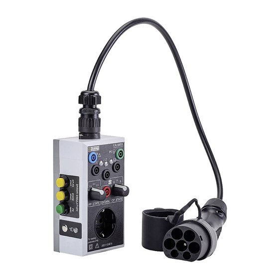
1.3. PRESENTATION Removable cable terminated by a type 2 connector. Specific connector. N terminal (neutral). Locking ring. PE terminal (protective C.A 6651 conductor or earth). E-MOBILITY TEST ADAPTER Terminals of phases L1, L2, and L3 with indicator. 20 A 13 A 32 A Charging switch (PP). -
Page 6: Side View
1.4. SIDE VIEW Position of the finger to test the earthing. Indicator. -
Page 7: Use
2. USE The tests can be performed only by or under the supervision of an EVCI-qualified electrician. In France, decree no. 2017-26 of 12/01/2017 concerning charging infrastructure for electric vehicles imposes stringent requirements. The EVCI-qualified electrician must observe the rules and standards required for their work, and is not allowed to skip steps needed to ensure the correct and safe use of the charging station. -
Page 8: Functional Test
„ Connect the cord with the type 2 connector to the CA 6651. Screw on the locking ring. „ Connect the type 2 connector to the charging terminal of the electric vehicle. -
Page 9: Check Of Electrical Safety
This test serves to check that the charging terminal is correctly supplied. „ Connect the cord with the type 2 connector to the CA 6651. „ Set the charging switch (PP) to N.C. and the mode switch (CP) to A. - Page 10 This measurement serves to check the connection of the charging terminal to earth. „ Set the charging switch (PP) to N.C. and the mode switch (CP) to A. „ Connect the installation tester to the CA 6651. Via the Schuko type connector (2P+E), for single-phase (L1, N, and PE terminals) ®...
- Page 11 At the end of the test, leave the RCD open in order to perform the no-voltage insulation test. 2.2.4. INSULATION MEASUREMENT This test must be performed with no voltage. None of the indicators of the CA 6651 must be lit. „ Connect the L1, L2, L3, and N terminals together and make an insulation measurement with respect to the PE.
-
Page 12: Test Of Operation Of The Charging Terminal
„ CP-PE voltage: +3V/-12V to 1kHz terminal. „ CP-PE resistance: 270Ω The CA 6651 short-circuits the Signal and PE terminals. Error on the CP signal The charging terminal ceases to operate for not more than 30 seconds. - Page 13 2.2.2. CHECK OF THE SIGNAL To check the signal, you must have a Handscope type oscilloscope. „ Connect the oscilloscope between the SIGNAL and PE terminals. N.C. The signals when the charging switch (PP) is set to N.C. take the following forms: +12 V +9 V -12 V...
-
Page 14: Test Report
When the mode switch (CP) is set to C or D and the charging switch is not set to N.C., the signal uses pulse width modulation (PWM) to indicate the available charging current (13A, 20A, 32A or 63A). The signals then take the following forms: +6 V +6 V -12 V... -
Page 15: Technical Characteristics
The mains connector is protected against overloads by a fuse. Type 2 connector: 32A, 3PH+N+PE, type E-2201, 200/346V-240/415V 3.3. POWER SUPPLY The CA 6651 is supplied by the charging terminal being tested via the type 2 connector. 3.4. ENVIRONMENTAL CONDITIONS For indoor use, outdoor use without rain. -
Page 16: Compliance With International Standards
3.6. COMPLIANCE WITH INTERNATIONAL STANDARDS The instrument is compliant with standards IEC 61010-1 and IEC 61010-2-30: 300V Category II, degree of pollution 2. Instrument with double insulation 3.7. ELECTROMAGNETIC COMPATIBILITY (CEM) Emission and immunity in an industrial environment per IEC 61326-1. -
Page 17: Maintenance
4. MAINTENANCE The instrument has no parts that can be replaceable by personnel who are not trained and approved. Any unauthorized repair or replacement of a part by an “equivalent” may gravely impair safety. 4.1. CLEANING Disconnect the unit completely. Use a soft cloth, dampened with soapy water. - Page 18 FRANCE INTERNATIONAL Chauvin Arnoux Chauvin Arnoux 12-16 rue Sarah Bernhardt Tél : +33 1 44 85 44 38 92600 Asnières-sur-Seine Fax : +33 1 46 27 95 69 Tél : +33 1 44 85 44 85 Fax : +33 1 46 27 73 89 Our international contacts info@chauvin-arnoux.com...
Need help?
Do you have a question about the CA 6651 and is the answer not in the manual?
Questions and answers