Table of Contents
Advertisement
Quick Links
Download this manual
See also:
User Manual
Contrôleur de disjoncteurs différentiels
Residual current device tester
Fehlerstrom-schutzschal terprüfer
Controllore interruttori differenziali
Controlador de interruptores diferenciales
F R A N Ç A I S
Notice de fonctionnement
E N G L I S H
User's manual
D E U T S C H
Bedienungsanleitung
I T A L I A N O
Libretto d'Istruzioni
E S P A N O L
Manual de Instrucciones
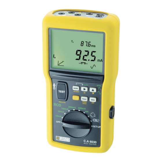
C.A 6030
1
Advertisement
Table of Contents

Related Manuals for Chauvin Arnoux C.A 6030


Summary of Contents for Chauvin Arnoux C.A 6030
- Page 1 C.A 6030 Contrôleur de disjoncteurs différentiels Residual current device tester Fehlerstrom-schutzschal terprüfer Controllore interruttori differenziali Controlador de interruptores diferenciales F R A N Ç A I S Notice de fonctionnement E N G L I S H User's manual D E U T S C H...
- Page 2 Category III meets the reliability and availability requirements of uses on fixed industrial installations (cf. EN 61010-1 + A2). Never use the C.A 6030 tester on installations having a potential greater than 550V with respect to earth.
-
Page 3: Table Of Contents
CONTENTS 1. PRESENTATION ..........................42 1.1 Environmental conditions ......................43 1.2 Compliance with standards and safety ................... 43 1.3 Power supply ..........................43 2. DESCRIPTION ..........................44 3. GENERAL USE ..........................47 3.1 Automatic chacks ........................47 3.2 Instrument configuration ( SET-UP ) ..................48 3.3 Compensation of the measuring cables .................. -
Page 4: Presentation
1. PRESENTATION Portable instrument for testing and checking the safety of new and existing electrical installations (residual current device tester). Measurement : - Voltage, - Frequency, - Test of protective conductor, PE, - Test of residual current devices (RCD) - Detection of the direction of phase rotation, - Calculation of shot-circuit currents, - Live ground resistance / loop measurement, - Current, with clip. -
Page 5: Environmental Conditions
Where the various indicators represente, respectively : position of the phase conductor full-wave signal for the testing of RCDs detected voltage probe measurement without triggering of differentials (signalling level) measurement smoothed for display measurement with triggering of differentials (power level) audible buzzer activated RCD test current reading in "pulse"... -
Page 6: Description
2. DESCRIPTION Preliminary remarks: Several types of action are possible on each key of the keypad, depending on whether the user presses the key briefly (short press, < 2s, validated by a beep) or at length (long press, > 2s, validated by a beep having a tone different from that of the beep emitted for a short press). In what follows, these different actions are symbolized as follows : for a short press on the key in question. - Page 7 10-position switch used to select the desired measurement function : Instrument off. RCD 10mA 30mA 100mA 300mA 500mA : Testing of residual current devices having ratings of 10mA, 30mA, 100mA, 300mA and 500mA. RCD var : Testing of residual current devices having ratings from 6mA to 650mA (rating chosen in SET-UP mode, see §3.2) Detection of direction of phase rotation Current measurement...
- Page 8 => select the memory block (OBJ) or line (TEST) for storage, retrieval on screen, or printing. PRINT PRINT MEM => switch the backlighting of the display unit on/off. => For the RCD positions of the switch : => selection of the type of measurement (pulse or sweep) for the testing of RCD.
-
Page 9: General Use
PRINT (PRINT MEM) key PRINT => print the last measurement made. PRINT => print the selected part of the memory (part or all). PRINT MEM Backlight LCD display unit Optical serial communication interface Safety input terminals, dia. 4mm, marked L (L1), N (L2), PE (L3), and (P) (terminal used for earth measurements in a live condition). -
Page 10: Instrument Configuration (Set-Up)
If U > U , where U is the touch voltage limit (U = 25 or 50 V, which can be parameterized in the “SET- UP” mode: see § 3.2), the instrument indicates that measurement is impossible. If a measurement is triggered, the instrument then monitors voltage U : if it increases by more than 20V, the instrument stops the measurement and reports an error. - Page 11 Parameter Presses Possible value Default values Euro (JJ/MM) Hour / Date successive US (MM/JJ) + MEM AAAA HH:mm Type of power supply bAtt bAtt niMH Activate / deactivate automatic shutdown Automatic shutdown time 01 to 59mn Activate / deactivate the buzzer serial no.
-
Page 12: Compensation Of The Measuring Cables
3.2.1 Parameterizing the default configuration This can be used to retore the delivery configuration. In SET-UP position : PUSH _btn TEST dFLt for validation and programming TEST of the default configuration PUSH _btn COMPENSATION OF THE MEASURING CABLES 3.3.1 Selection of type of compensation There are 3 types of compensation of the measuring cables: “nOnE”... -
Page 13: Recording Measurement Results ( Mem )
=> Perform a long press . Upon release, the compensation measurement is triggered (duration: TEST approximately 30s.). => Perform another log press on the key to return to voltage measurement. TEST Possible error messages : Display - Indication Remark - Possible cause The instrument detects a voltage greater than 2V between two of the terminals L, N, and/or PE : the compensation is not applied. -
Page 14: Consulting Recorded Values ( Mr )
CONSULTING RECORDED VALUES ( MR ) The group of measurements (OBJ) and the measurement (TEST) to be retrieved on the display unit are selected using the keys. ERASING RECORDED VALUES The memory of the instrument can be erased, totally or patially, in the "SET-UP" mode : the table bellow summarizes the various erasure procedures : Complete erasure of Erasure of a memory block... -
Page 15: Printing Measurement Results ( Print )
PRINTING MEASUREMENT RESULTS ( PRINT ) : print the measurement made and all of the parameters attached to it. PRINT Examples of printing tickets : Remark : In the SET-UP position, pressing the key triggers printing of the configuration of the PRINT instrument. -
Page 16: Measurements
4. MEASUREMENTS VOLTAGE MEASUREMENT 4.1.1 Description of the function The voltage measurement is accessible on all RCD positions of the switch and the position. 4.1.2 Preparation of the measurement (connection) => switch the instrument on, => connect the instrument to the installation using the measuring cable terminated by a mains socket, =>... - Page 17 Parameters accessible in the phase rotation position See § 4.3.4. Parameters accessible in the current measurement setting: MORE MORE Initial display press) press) ---- Initial display ALARM ---- press) ALARM ---- press) ALARM Pressing the key once causes a return to the initial display. MORE 4.1.5 Characteristics 4.1.5.1 Measurement ranges and accuracy...
- Page 18 4.1.5.1 Influencing quantities Variation of the measurement Limits of the domain of Influencing quantities Typical Maximum 1%/10 °C ± 1pt Temperature -10 to + 55 °C 2%/10 °C + 2pt Relative humidity 10 to 85% RH at 45°C 3% + 2 pt Power supply voltage 6.8 to 10 V 1% / V + 1pt...
-
Page 19: Test Dof Residual Current Devices
TEST OF RESIDUAL CURRENT DEVICES This function is used to test the correct dimensioning of the residual current devices and their correct operation. Two test modes are possible: test without triggering (see §4.2.1) : => The instrument performs only a loop measurement (or live ground measurement if the voltage probe is connected) test with triggering (see §... - Page 20 => If necessary, in the SET-UP mode, adjust : the threshold voltage U (see § 3.2), the measurement current "I.ntP" according to the nominal current I of the RCD (see §3.2), ∆N Note : The choice of IntP (0.4I by default) may depend on the technology of the RCD and also allows ∆N testing without disconnecting the load downstream of the RCD.
- Page 21 => Set the switch to one of the RCD positions, according to the nominal rating of the RCD to be tested. Note : the "var." position is used to adapt to non-standard nominal ratings. => Perform a compensation of the measurement cables (see § 3.3). =>...
- Page 22 Loop measurement (no voltage probe connected) MORE MORE MORE MORE MORE Initial display press) press) press) press) press) ---- ∆PE Initial display L ALARM KLPE ---- ∆L press) L ALARM KLPE ---- ∆N press) L ALARM KLPE Pressing the key once more causes a return to the initial display. MORE Live ground measurement (voltage probe connected) MORE...
- Page 23 4.2.1.5.1 Measurement ranges and accuracy Characteristics of loop measurements in the RCD position: Nominal rating 10 mA 30 mA 100 mA ∆ 4000 Ω 400 Ω 4000 Ω 400 Ω 4000 Ω Display range 40 kΩ Specified 20 - 4.00 – 10.00 7.0 –...
- Page 24 4.2.1.5.2 Influencing quantities Variation of the measurement Limits of the domain of Influencing quantities Typical Maximum 1%/10 °C ± 1pt Temperature -10 to + 55 °C 2%/10 °C + 2pt Relative humidity 10 to 85% RH at 45 °C 3% + 2 pt 1% / V ±...
- Page 25 => if U < U (see § 3.2), the instrument performs a non-tripping test. When the , key is pressed, TEST the instrument: measures voltages U , and U and the voltage between PE and ground, checks the probe resistance if the probe is connected, applies, for 1000ms, a current that depends on the nominal rating I (<...
- Page 26 => Use the key to choose the desired type of test (sweep or pulse) : Initial state Test in "sweep" mode press, long) Test in "pulse" mode at I ∆N press) Test in "pulse" mode at 2 x I ∆N press) Test in "pulse"...
- Page 27 Note : an "upstream-downstream" connection makes it possible to trip a residual current device even if there is a residual current device having a lower rating upstream of it. This method can be used with single-phase current or with three-phase current, either with a neutral (in this case the nominal phase-to-neutral voltage must not exceed 400V) or without a neutral (in this case the nominal phase-to-phase voltage must not exceed...
- Page 28 MORE MORE MORE MORE press) press) press) press) ---- ∆L Initial display L ALARM L ALARM ---- ∆PE L ALARM press) L ALARM ---- ∆N L ALARM press) L ALARM ---- press) L ALARM L ALARM is displa yed only in "sweep" mode is displayed only for the "var."...
- Page 29 Characteristics in "sweep" mode : Nominal ratings I 10 mA – 30 mA – 100 mA – 300 mA – 500 mA - “var.” (6 mA to 650 mA) ∆ Loop measurement Non-tripping test Tripping test Type of test 0.1I to 0.5I ∆...
-
Page 30: Test Of The Direction Of Phase Rotation
4.2.2.6 Warnings or error reports Preliminary remark : The complete list of coded errors is given in § 7. Display - Indication Remark - Possible cause The temperature of the instrument is too high: the > 80°C measurement is stopped. Pressing the key has no TEST effect until the temperature of the instrument is again below... - Page 31 "3-wire" measurement : When the key is pressed, the instrument : TEST measures and checks the voltage and the frequency, measures the phase difference between the 3 phases and displays the direction of phase rotation: "1.2.3." if the phase order is direct, "3.2.1." if the order of the phases is reversed "2-wire"...
- Page 32 "3-wire" measurement : MORE Intitial display press) Initial display sens press) sens press) sens Pressing the key once more causes a return to the initial display. MORE "2-wire" measurement : MORE Initial display press) Initial display sens press) sens Pressing the key once more causes a return to the initial display.
-
Page 33: Current Measurement
4.3.6 Warnings or error reports Preliminary remark: The complete list of coded errors is given in § 7. Display - Indication Remark - Possible cause One of the voltages needed for determination of the phase rotation is < 90 V. <... - Page 34 PUSH MORE > direction of alarm (> or<) 88.88 location of decimal point 88.88 setting of the value of each of the 4 digits, 88.88 selected by successive presses on the PUSH => If necessary, actvate alarm threshold I ALARM 4.4.3 Measurement procedure The measurement is started automatically and is continuous.
- Page 35 Characteristics with an C 172 current probe : Display range 400mA Specified measurement 50.0-399.9mA 0.400-3.999A 4.00-20.00A domain Accuracy 2%+10pt 1,5%+2pt 1,2%+2pt 4.4.5.2 Influencing quantities Variation of the measurement Limits of the domain of Influencing quantities Typical Maximum 1%/10 °C ± 1pt Temperature -10 to + 55 °C 2%/10 °C + 2pt...
-
Page 36: Glossary
5. GLOSSARY frequency of the signal current current threshold ALARM effective operating current of the RCD (sweep test). nominal rating of the residual current device to be tested ∆ short-circuit current between terminals L and N, L and PE, and N and PE KLPE KNPE test current in the test of an RCD without triggering... -
Page 37: Maintenance
Customer Service Department or an approved repairer. Repair under and out of warranty: Send the instrument to one of the MANUMESURE regional agencies, approved by Chauvin Arnoux Information and coordinates on request: Tel.: 02 31 64 51 43 - Fax: 02 31 64 51 09 Repair outside mainland France: For any repair (under or out of warranty), send the instrument back to the dealer. -
Page 38: List Of Coded Errors
7. LIST OF CODED ERRORS Error Meaning code Er02 Incorrect wiring or connection error: L and PE reversed Er03 Incorrect wiring or connection error: L missing Er07 Earth potential too high (potential danger): measurement STOPPED Untimely interruption of the current during the measurement of Z (earth fault breaker Er08 tripped?) -
Page 39: To Order
8. TO ORDER C.A 6030 Residual current device tester (Euro) ---------------------------------------------- P01.1915.11 C.A 6030 Residual current device tester (GB) ------------------------------------------------ P01.1915.11A C.A 6030 Residual current device tester (IT) -------------------------------------------------- P01.1915.11B C.A 6030 Residual current device tester (CH) ------------------------------------------------ P01.1915.11C C.A 6030 Residual current device tester (US) ------------------------------------------------ P01.1915.11D Delivered in a “necklace”...
Need help?
Do you have a question about the C.A 6030 and is the answer not in the manual?
Questions and answers