Table of Contents
Advertisement
CONTROLEUR "MACHINE"
MACHINE TESTER
MASCHINEN-TESTER
MACHINE TESTER
COMPROBADOR DE MAQUINARIA
ELECTRICA
F R A N C A I S
E N G L I S H
D E U T S C H
I T A L I A N O
E S P A Ñ O L
Office: Jl. Radin Inten II No. 62 Duren Sawit, Jakarta 13440 - Indonesia
Workshop: Jl. Pahlawan Revolusi No. 22B, Jakarta 13430 - Indonesia
Phone: 021-8690 6777 (Hunting)
REMOTE
WARNING LAMP 12V~
INSULATION (M ) Ω
500 - 1000 V
+
CONTINUITY 12V/>10A
C1
P1
DIELECTRIC (HV)
1 - 1.25 - 1.5 kV
User's Manual
C.A 6121
MΩ
500V
150M
113.5
RS232C
MΩ
DISCHARGE TIME ( t)
∆
Un
Rmin
TEST
600V CAT III
MAINS
TEST
~
( U,R
)
∆
10A
P2
C2
CHAUVIN
ARNOUX
~
Mobile: +62 816 1740 8925
Fax: 021-8690 6771
230V / 50Hz
600VA
Ω
U=513V
9min 59s
Timer
ON
OFF
TEST ON
C.A 6121
MACHINE TESTER
START / STOP
Advertisement
Table of Contents

Related Manuals for Chauvin Arnoux C.A 6121


Summary of Contents for Chauvin Arnoux C.A 6121
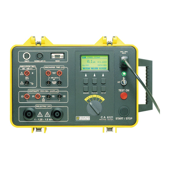
- Page 1 C.A 6121 CONTROLEUR "MACHINE" MACHINE TESTER MASCHINEN-TESTER MACHINE TESTER COMPROBADOR DE MAQUINARIA ELECTRICA 230V / 50Hz 600VA MΩ 500V 150M Ω 113.5 REMOTE WARNING LAMP 12V~ RS232C MΩ U=513V 9min 59s INSULATION (M ) Ω DISCHARGE TIME ( t) ∆...
-
Page 2: Safety Precautions
I If a fuse has blown in the instrument, please follow the instructions in this manual to replace it! I Any repair or metrological check procedure must be carried out by competent and approved personnel! I The C.A 6121 MACHINE TESTER must only be handled by a competent operator, familiar with equipment using dangerous voltages ! I Use connection accessories whose overvoltage category and service voltaage are greater than or equal to those of the circuits on which the measurements are made. -
Page 3: Table Of Contents
WARRANTY Our guarantee is applicable for twelve months after the date on which the equipment is made available (extract from our General Conditions of Sale, available on request). CONTENTS GENERAL PRESENTATION ..............................28 DESCRIPTION OF THE INSTRUMENT ..........................28 TECHNICAL SPECIFICATIONS ............................29 3.1. -
Page 4: General Presentation
600V CAT III MAINS TEST TEST ON CONTINUITY 12V/>10A ( U,R ∆ MEM/MR MEM/MR PRINT/RS PRINT/RS SET-UP / SET-UP DIELECTRIC (HV) CHAUVIN C.A 6121 ARNOUX START/STOP MACHINE TESTER 1 - 1.25 - 1.5 kV Fig.1. Presentation of the front panel... -
Page 5: Technical Specifications
REMOTE connector to connect a REMOTE CONTROL PEDAL WARNING LAMP connector to connect external WARNING LAMPS (standard VDE 104) RS 232 connector to connect external printer or PC DISCHARGE TIME - TEST terminals to be used in four pole measurement DISCHARGE TIME - MAINS TEST terminals to be used in 2 or 4 pole measurement LCD dot matrix display with continuous back light GENERAL KEYS (see the function of each key on the LCD) -
Page 6: Voltage Drop At 10 A Ac (Position ∆U)
3.2. VOLTAGE DROP SCALED TO 10 A AC (POSITION ∆ ∆ ∆ ∆ ∆ U) I Voltage drop readout : Range ∆U (V) Resolution (V) Accuracy 0 - 10 0.01 ±(2% of the reading + 0.02 V) I Test voltage readout : Range (V) Resolution (V) Accuracy... -
Page 7: Insulation Resistance
3.4. INSULATION RESISTANCE 3.4.1 Nominal voltage 500 V DC I Insulation resistance readout : Range* (MΩ) Resolution (kΩ) Accuracy 0 - 1.999 2.00 - 19.99 ±(2% rdg + 2 counts) 20.0 - 199.9 200 - 500 1000 ±10% rdg * gammes automatiques I Range : 0 - 200 MΩ... -
Page 8: General Specifications
: High tension test techniques for low voltage equipment EN 61326-1 : EMC - Emissions and immunity 4. MEASUREMENTS 4.1. DIELECTRIC TEST TESTED INSTRUMENT C.A 6121 MACHINE TESTER 1 kV 1.25 kV 1.5 kV 1-1.25-1.5 kV 230 V/50 Hz LOAD LOAD Fig. - Page 9 i = i + i i ..absolute value of current i ..capacitive current i ..resistive current -jIm Fig. 3. Test current diagram How to perform the measurement ? 1. Set the rotary switch to the HV (high voltage) position; the following screen is displayed : Nominal test voltage Tripping out current 1000V...
-
Page 10: Voltage Drop Scaled To 10 A (Position ∆U)
6. Save the displayed result for documentation purposes (refer to the instructions in chapter 5.2. to find out the procedure for saving the displayed result). 4.2. VOLTAGE DROP SCALED TO 10 A AC (POSITION ∆ ∆ ∆ ∆ ∆ U) C.A 6121 MACHINE TESTER OBJECT UNDER TEST TEST ∆U... -
Page 11: Low Resistance (Position R 10A )
DIELECTRIC (HV) or press the START/STOP key again to stop the measurement. >10 A AC (for R : 0...500 m ) W test CHAUVIN C.A 6121 ARNOUX START / STOP 1 - 1.25 - 1.5 kV MACHINE TESTER 6. Save the displayed result for documentation purposes (refert to Fig.11. -
Page 12: Insulation Resistance
1 - 1.25 - 1.5 kV MACHINE TESTER Fig.14. Connection of the test leads 4.4. INSULATION RESISTANCE C.A 6121 MACHINE TESTER OBJECT UNDER TEST 500/1000 V DC Fig.15. Test circuits How to perform the measurement ? 1. Set the rotary switch to MΩ Ω Ω Ω Ω position(insulation resistance); the following screen is displayed. -
Page 13: Discharge Time - 2 Pole System
Fig.18. Connection of the test leads 60 V and do not touch the test terminals during that time. 4.5. DISCHARGE TIME - 2 POLE SYSTEM OBJECT UNDER TEST C.A 6121 MACHINE TESTER MAINS TEST 230 V/50 Hz Fig.19. Test circuits expected... -
Page 14: Discharge Time - 4 Pole System
PRINT/RS SET-UP disconnection voltage (see fig.20) is displayed when the measurement DIELECTRIC (HV) 96 MW CHAUVIN C.A 6121 START / STOP 1 - 1.25 - 1.5 kV ARNOUX MACHINE TESTER is finished. I I I I I ∆t < 0.1 s is displayed under the main result and no voltage is displayed Fig.22. -
Page 15: Operation
5. OPERATION 5.1. WARNINGS Different warnings in addition to information can be displayed during operation of the C.A 6121 MACHINE TESTER. See below a list of warnings and information for each function. I I I I I HV function : Trip out : The HV generator tripped because the test current was higher than the set threshold value. -
Page 16: Memorising The Results
5.2. MEMORISING THE RESULTS Any displayed result can be saved in one of 999 memory locations. The associated results as well as the test parameters are saved at the same time as the main results and can be recalled or printed out later. Each result is allocated a memory number (No.) and a machine number (MACH) e.g.: No:025 MACH:003... -
Page 17: Rs232 Communication (For Printout And Connection To A Pc)
C.A 6121 ARNOUX MACHINE TESTER START / STOP 1 - 1.25 - 1.5 kV Fig.30. Connection of C.A 6121 MACHINE TESTER to PC (to 25 pin or 9 pin connector) front view front view male, 25 pin female, 9 pin... - Page 18 I I I I I How to transfer stored data to serial printer or PC ? 1. Connect the C.A 6121 MACHINE TESTER to the serial printer or to the PC (see figures 28 to 30) using the appropriate RS232 communication cable and adapters.
-
Page 19: Erasing The Results
Print selection : Key used : Machine number on the left starts flashing. Select start machine number. Machine number on the right starts flashing. Select end machine number. Exit selection mode. Impression de tous les résultats enregistrés sous les numéros de machine compris entre celui de départ et celui de fin que vous avez sélectionnés. -
Page 20: Reinitialising The Instrument
5.6. REINITIALISING THE INSTRUMENT I I I I I To reinitialise all the test parameters, please follow the procedure below: 1. Switch off the instrument by setting the ON/OFF key to the OFF position. 2. Press the SET UP key and keep it pressed while switching on the instrument. Machine Tester followed by Hard Reset are displayed for a few moments, then the main menu opens. -
Page 21: Configuration
5.7. CONFIGURATION 5.7.1. Display contrast SOFTWARE VERSION MT 1.00 If the display is not sufficiently readable (screen too dark or lettering intensity too low), the display contrast must be reinitialised. TIME : 11:33 DATE : 26-06-97 How to set the contrast ? CONT. -
Page 22: Baud Rate
ARNOUX MACHINE TESTER Pedal switches Fig.41. Connection of the remote control pedal to the C.A 6121 MACHINE TESTER NOTE : When the remote control pedal is connected to the instrument, the START function on the front panel is not operational, whilst the STOP function is operational. -
Page 23: Use Of Warning Lamps (Standard Vde 104)
START / STOP 1 - 1.25 - 1.5 kV ARNOUX MACHINE TESTER Fig.43. Connection of the warning lamps to the C.A 6121 MACHINE TESTER I I I I I Technical specifications of the warning lamps: Cable length : 2 m Bulbs...
Need help?
Do you have a question about the C.A 6121 and is the answer not in the manual?
Questions and answers