Table of Contents
Advertisement
Advertisement
Table of Contents

Related Manuals for Chauvin Arnoux C.A 6160


Summary of Contents for Chauvin Arnoux C.A 6160
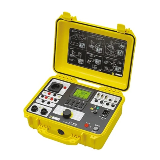
- Page 1 C.A 6160 APPLIANCE MULTITESTER E N G L I S H User’s Manual...
-
Page 2: Table Of Contents
CONTENTS 1. GENERAL INTRODUCTION..................................p. 3 Safety in use....................................p. 3 Warranty......................................p. 4 List of measurements carried out by the instrument........................p. 4 List of applicable standards................................p. 4 2. DESCRIPTION OF THE INSTRUMENT..............................p. 5 3. TECHNICAL SPECIFICATIONS................................p. 6 Withstanding test (PROG. HV and HV position)........................p. 6 Burn out (HV position)..................................p. -
Page 3: General Introduction
1. GENERAL PRESENTATION SAFETY IN USE Use the instrument in accordance with the manual, otherwise the instrument may be dangerous for the operator! Read this instruction manual carefully, otherwise use of the instrument may be dangerous for the operator, for the instrument or for equipment under test! Use only grounded mains outlets to supply the instrument! Do not use any damaged mains outlet or damaged mains connection cable! -
Page 4: Warranty
Main plug Dangerous voltage is present on the FUSES - switch off the instrument and disconnect all test cables and mains cord before replacing the fuses or opening the instrument. WARRANTY Unless stated differently, our instruments are guaranteed against any manufacturing or material defect. They do not bear the specification known as the safety specification. -
Page 5: Description Of The Instrument
2. DESCRIPTION OF THE INSTRUMENT Fig.1. Front panel layout Legend: LCD dot matrix display with continuous backlight T16A 250V 6.3x32 fuses protect test socket from overloading RS 232 connector to connect external printer or PC EXT/DOOR IN connector BAR CODE READER connector REMOTE connector to connect REMOTE CONTROL PEDAL WARNING LAMP connector to connect WARNING LAMP F 2.5A 250V fuses protect instrument’s power supply... -
Page 6: Technical Specifications
3. TECHNICAL SPECIFICATIONS 3.1 WITHSTANDING TEST (PROG. HV AND HV POSITION) Nominal test voltage : adjustable (100/5000) V (50,60) Hz at U = 230V, P = 500VA mains load Open circuit test voltage : (nominal test voltage) (-1% / +10%) at U = 230V mains Output differential :... -
Page 7: Low Resistance (Continuity Position)
3.3. LOW RESISTANCE (CONTINUITY POSITION) Resistance readout for current 10 A and 25 A Resolution ( Ω ) Range R ( Ω ) * Accuracy ±(3 % of reading + 3 dig.) 0.000 - 0.999 0.001 ±(3 % of reading + 10 dig.) 1.000 - 2.000 0.001 2.001 - 9.999... -
Page 8: Voltage Drop Scaled To 10A~ (Option In Continuity Position)
3.4. VOLTAGE DROP SCALED TO 10 A~ (OPTION IN CONTINUITY POSITION) Voltage drop readout (scaled to 10A Range ∆U (V) Resolution (V) Accuracy ±(3 % of reading + 3 dig.) 0.00 – 10.00 0.01 10.00 – 99.99 0.01 indicator only Test current readout Range (A) Resolution (A) -
Page 9: Leakage Current
3.6. LEAKAGE CURRENT 3.6.1. LEAKAGE CURRENT Leakage current readout: Range (mA) Resolution (mA) Accuracy ±(5 % of reading + 3 dig.) 0.00 – 3.99 0.01 ±(5 % of reading + 3 dig.) 4.0 – 20.0 Settable limits: .......... (0.1 – 20.0) mA (in step of 0.1 mA) Output: ............ -
Page 10: Discharge Time (Disc.time Position)
Frequency readout Range (Hz) Resolution (Hz) Accuracy ±(0.1% of reading +3 dig.) 45.00 – 65.00 0.01 Threshold Apparent Power: ......... adjustable (10 - 3500) VA (10 - 100) VA (resolution 1 VA) (100 - 3500) VA (resolution 10 VA) Output: ..............16 A power test socket Timer: .............. -
Page 11: Measurements
Accuracies apply for 1 year in reference conditions. Temperature coefficient outside this limits is 0.1% of measured value per C° and 1 digit. Withstanding proof test: Between mains and withstanding terminals 7500 Veff / 1 min Between mains and other terminals or accessible metallic parts 2200 Veff / 1 min 4. - Page 12 How to carry out the measurement STEP 1. Set rotary switch to HV (high voltage) position. The following heading is displayed: T ripp in g o u t c u rrent F u n ctio n n a m e N o m in al test v o lta g e L e a k a ge c u rre n t C h arac te r o f se le c te d pa rt o f le ak a g e cu rre n t...
- Page 13 Use ↑ and ↓ keys to select appropriate trip-out current. Press Chr I in order to change the character of displayed part of leakage current. If the selected part is resistive, sign is displayed behind mA unit. For capacitive part sign is displayed behind mA unit.
-
Page 14: Withstanding Test With Preset Voltage/Time Diagram
STEP 3. Connect test probes (pistols) to the instrument as shown in figure below. Fig. 9. Connection of test probes STEP 4. Close DOOR IN safety connector, if enabled. (CONTINUITY test terminals must be open). STEP 5. Press START/STOP key to start high voltage generator and carry out the test using test probes. STEP 6. - Page 15 T ripp in g o u t c u rre nt P ro g k ey to se le ct p ro g ra m in g m e n u Fig. 10. Main menu in PROG.HV function STEP 2. Press Prog. key to set or to check programmed ramp values in order to prevent damage to the equipment under test (last values used are memorized).
-
Page 16: Low Resistance Test With Current Of >0.1A / 0.2A / 10A / 25A
4.3. LOW RESISTANCE TEST WITH CURRENT OF >0.1A / 0.2A / 10A / 25A~ CONTINUITY position APPLIANCE MULTITESTER OB JECT UNDER TEST C.A 6160 TE S T ∆U (0 - 23 0) V / (50,60) H z L O A D regulate d Fig. -
Page 17: Voltage Drop Scaled To Test Current Of 10A
- Use ↑ and ↓ keys to select appropriate threshold value. If the displayed result is higher than the set threshold limit, the result will be accompanied by an error sound signal (after completion of the measurement). No threshold value will be selected and no sound signal will be activated when «... -
Page 18: Insulation Resistance
T h re sh o ld v o lta g e d ro p /w ire se c tio n Vo lta g e d ro p s c a le d to 1 0 A (m a in re s u lt) S e t tim er v a lu e Te s t c u rre n t Te s t v o lta g e... - Page 19 How to carry out the measurement STEP 1. Set rotary switch to ISO (insulation resistance) position, the following heading is displayed N o m in al te st v o lta g e T h re sh old in su la tio n resistan ce In su latio n re sistanc e M easu red test v o ltag e...
-
Page 20: Discharge Time - External (Input Mains Test)
STEP 4. Press START/STOP key to start the measurement. STEP 5. Wait for test time to elapse (if the timer has been switched on) or press START/STOP again stop measurement. STEP 6. Save displayed result for documentation purpose (see instruction in chapter 5.2. on how to save displayed result). NOTE ! Do not disconnect measured object before it is discharged. -
Page 21: Discharge Time-Internal
STEP 7. Save displayed result for documentation purposes (see instructions in chapter 5.2. on how to save displayed result). 4.7. DISCHARGE TIME-INTERNAL OB JECT UN DER TEST APP LIANC E M ULTITESTER C.A 6160 res t v o lta ge T E S T tes t Fig. -
Page 22: Leakage Current
STEP 7. Save displayed results for documentation purpose (see instruction in chapter 5.2. on how to save displayed results). 4.8. LEAKAGE CURRENTS 4.8.1. LEAKAGE CURRENT T E S T APP LIANCE M ULTIT ESTER O BJECT UNDER TEST S O C K E T C.A 6160 Fig. 32. Test circuitry... -
Page 23: Touch Leakage Current
STEP 6. Save displayed result for documentation purpose (see instructions in chapter 5.2. on how to save displayed result). 4.8.2. SUBSTITUTE LEAKAGE CURRENT APPLIANCE MULTITESTER OB JECT UNDER TEST C.A 6160 230 V/(50,60) H z 40V /(50,60) H z T E S T S O C K E T Fig. -
Page 24: Substitute Leakage Current
How to carry out the measurement STEP 1. Set rotary switch to LEAKAGE position. STEP 2. Select test parameters as follows: Pres Syst. Key to select subst Fig. 36. Heading in Substitute Leakage current function Set Leakage current threshold Press Ilim key to open menu to change leakage current threshold value. Use ↑... -
Page 25: Functional Test
How to carry out the measurement STEP 1. Set rotary switch to LEAKAGE position. STEP 2. Select test parameters as follows: Pres Syst. Key to select touch Fig. 39. Heading in Touch Leakage current function Set Leakage current threshold Press Ilim key to open menu to change touch leakage current threshold value. Use ↑... -
Page 26: Autotest
How to carry out the measurement STEP 1. Set rotary switch to FUNCTION. TEST position, the following heading is displayed. Va lu e s re la te d to te s te d ob je c t A p p a re nt p o w e r th re sh old v a lu e Te ste d o b je c t c u rre n t L in e v o lta g e A c tiv e po w e r... - Page 27 Fig. 43. Main CE Link window For more information on options in sequence editor see chapter 7, PC software - CE Link. When the sequence is completed it must be sent to APPLIANCE MULTITESTER by using serial RS232 interface. After sending it, the PC does not need to be connected to the APPLIANCE MULTITESTER.
- Page 28 STEP 4. Send programmed sequence to DIELECTRIC STRENGTH TESTER from “List of instrument’s programs” menu by using Send button. After the transfer is completed the name of the user designed procedure is displayed on the list of programs. Up to 10 sequences can be sent to the instrument. P re ss V iew k ey v ie w se qu e n c e ste p s...
-
Page 30: Operation
5. OPERATION 5.1. WARNINGS Different warnings or information can be reported during manipulation with the APPLIANCE MULTITESTER. Here is a list of warnings and information for each function. HV AND PROG.HV FUNCTION: Trip out The HV generator tripped-out due to the test current, which was higher than the set threshold value. -
Page 31: Results Memorizing
5.2. RESULTS MEMORIZING Each displayed result can be stored to one of 1638 memory locations. In addition to the main result all subresults and test parameters are also saved and can be recalled and downloaded to PC. Each result is marked with memory index (Memory:______), device number (Device:______) and device barcode number (Barcode:______). -
Page 32: Recalling Of Stored Results
5.3. RECALLING OF STORED RESULTS The results can be recalled only before the measurement is performed or after the result is saved. STEP 1. Press MEM key in order to reach memory menu for recalling results (see fig. below). Fig. 50. Memory heading for recalling from memory STEP 2. -
Page 33: System Configuration
R S 2 32 C o m m u n ication cab le Fig. 53. Connection of APPLIANCE MULTITESTER to PC How to transfer stored data to PC STEP 1. Connect APPLIANCE MULTITESTER to PC as shown in fig. 53 using appropriate RS 232 communication cable. STEP 2. - Page 34 BARCODE READER BAUD RATE setup: Use Sel. keys to select appropriate baud rate from: 2400, 4800 or 9600. After exit, the new baud rate will be confirmed and basic menu is displayed. CLEAR all RECORDS: Press Enter to confirm or Exit to cancel. NOTE ! Device and bar code numbers will not be erased.
- Page 35 List of test parameters for each function, and their initial values: F u n c t i o n P a r a m e t e r R a n g e o f a d j u s t m e n t o r p o s s i b l e In i t i a l v a l u e v a l u e s = 1 k V...
-
Page 36: Contrast Of The Display
5.6. CONTRAST OF THE DISPLAY Where there is insufficient readability of the display (display too dark or intensity of messages too weak), the appropriate contrast of the display should be set. How to set appropriate contrast It is possible to adjust contrast in all positions of main switch. STEP 1. -
Page 37: Use Of Wraning Lamp
How to operate REMOTE CONTROL pedal START/STOP function on the pedal is exactly the same as on front panel of the instrument when the pedal is not connected. SAVE function on the pedal is automatic, so a double press to SAVE pedal is required to save displayed result to the next location of set device number. -
Page 38: Use Of Barcode Reader
5.9. USE OF BARCODE READER R S 232 C om m unica tio n c able Fig. 58. Connection of barcode reader to APPLIANCE MULTITESTER Use a barcode reader that includes RS232 communication with DB9 (male) connector. Select baud rate for barcode reader (see chapter 5.5 System configuration) To add a barcode number to the currently enabled device use serial barcode reader. - Page 39 PASS / FAIL: In autotest and individual measurements the status of measurement (PASS / FAIL) is given on pin 2 of EXT / DOOR IN connector. If the measurement result is inside the range of limit then pin 2 is HI level. If the measurement is out of limit range then pin 2 is LO level.
-
Page 40: Maintenance
6. MAINTENANCE 6.1. METROLOGICAL CHECK It is essential that all measurement instruments are regularly calibrated. We recommend an annual calibration to be carried out. 6.2. SERVICE Repairs under or out of guarantee: Please return the products to your distributor. 6.3. CLEANING To clean the surface of teh instrument, use a soft cloth slightly moistened with soapy water or alcohol. -
Page 41: Pc Software - Ce Link
7. PC SOFTWARE - CE LINK 7.1. INSTALLING CE LINK CE Link software is 32-bit application for Windows platforms. Before installing CE Link it is recommended to close all running programs on your PC. After installation is complete there is no need to restart computer Insert installation disc in your computer and run SETUP.EXE. -
Page 42: Download Data
Download data: Port settings: Opens window for downloading or auto - Opens window for port and downloading data from baud rate settings. Appliance MultiTester to Shortcut key: Alt S + P Shortcut key: Alt F + D Open data file: Help: OPENS WINDOW FOR ANALY-ZING... - Page 43 Fig. 64. Port settings window Check baud rate on APPLIANCE MULTITESTER by using SET key (see SERIAL PORT BAUD RATE setup in SYTEM CONFIGURATION in chapter 5.5) Prepare APPLIANCE MULTITESTER for communication by pressing RS232 key (instrument will go in communication mode).
-
Page 44: Open Data File
For auto download from instrument (instrument must be in the Autotest mode) choose AutoReceive download option. In this mode PC waits to receive record from the instrument. Instrument sends record to the PC at the end of each sequence procedure. After downloading the sequence will be executed again. For details of sequence creating see chapter 7.6 Sequence editor (in program definition window AutoSend option has to be enabled) Fig. - Page 45 Fig. 69. Selecting file “example2. DTA” After selecting the desired data file and pressing Open downloaded data will be displayed in the table form. Table organization is same as in instruments internal memory; from Device 1 to last Device (max 255) with saved results, - see chapter 5.2.
- Page 46 New / Edit Device: Adds description, edits Copy: dev ice or barcode num ber Copies selected row. or creates new dev ice. Shortcut key: Shortcut key: Ctrl+C, Alt E + C Alt E + N Insert / Edit comment: Cut: Inserts row with com m ent or Cuts selected row.
-
Page 47: Printing Documents
7.5. PRINTING DOCUMENTS 7.5.1 PRINTING SELECTED ROWS Selected rows can be printed following this steps: 1. Select rows to be printed (use Shift + left mouse button for selecting subsequent records to record or Ctrl + left mouse button for selecting one row by one). -
Page 48: Print Separately
Fig. 72. PRINT preview 7.5.2 PRINT SEPARATELY Print separately function prints each measured device results to its own document. It is intended to print separate reports for each tested object (production line testing). -
Page 49: Header Programming
7.6. HEADER PROGRAMMING Fig. 73. Header programming window This window represents info window for your instrument (called header). To see instrument header the instrument has to be connected to PC. User can change “User string” (max 48 characters), send system time (time and date set on the PC). It is possible to change User string only in this way. -
Page 50: Sequence Editor
7.7. SEQUENCE EDITOR Basic point of Sequence editor is displayed in chapter 4.10. AUTOTEST. The user will use Sequence editor to create desired sequences or to edit existing sequence on the instrument. Max. number of steps in one sequence is 50, including programmed pause, messages, barcode reader sequence and sound signals. - Page 51 Voltage drop Parameter window Continuity Current Parameter window High Voltage Parameter window Programed High Voltage Parameter window Insulation Parameter window Sound Parameter window...
- Page 52 Pause Parameter window Leakage Current Parameter window Message Parameter window Fig. 75. Parameter windows To set program name in Command table select Program name. In this dialog box user can also enable: - pause (0 s – 5 s) between each test of the sequent, - saving of measurement results, - increment device number for successive sequence results, - auto send each sequence results to PC (suitable for automate of production lines).
- Page 53 List of instrument Clear row data: programs: Clears only data, not whole Reads, delete and sends row. sequence to instrument. Shortcut key: Shortcut key: Alt S + P Alt F + D Get command: Insert empty row: Copies selected command Inserts an empty row at from command table to selected row (for a new...
-
Page 54: To Order
8. TO ORDER C.A 6160 APPLIANCE MULTITESTER (GB) ------------------------------------------------------------------------------- P01.1458.01A C.A 6160 APPLIANCE MULTITESTER (EURO) --------------------------------------------------------------------------- P01.1458.01 Standard supply : - 1 power supply lead (Euro or GB) - 2 dielectric test guns (probes) with cable 2m - 2 insulation test leads, 3m (1 red, 1 black) - Page 55 02 - 2004 Code 691030A02 - Ed.1 Deutschland - Straßburger Str. 34 - 77694 KEHL /RHEIN - Tél : (07851) 99 26-0 - Fax : (07851) 99 26-60 España - C/ Roger de Flor N°293 - Planta 1 - 08025 BARCELONA - Tél : (93) 459 08 11 - Fax : (93) 459 14 43 Italia - Via Sant’...
Need help?
Do you have a question about the C.A 6160 and is the answer not in the manual?
Questions and answers