
Subscribe to Our Youtube Channel
Summary of Contents for Pace PAI
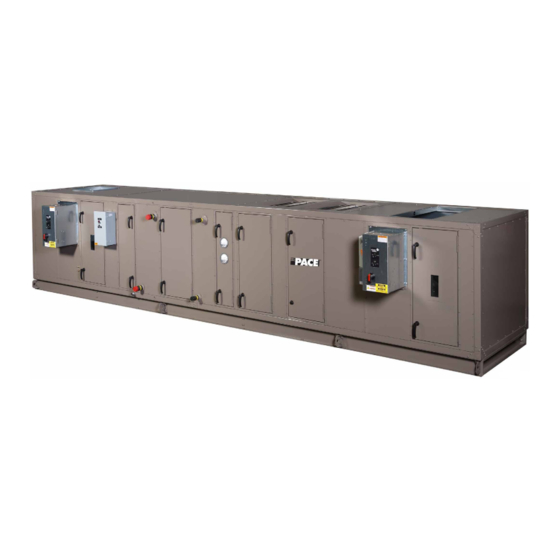
- Page 1 Installation and Assembly Manual Form PA102.20-N1 (718) │ Supersedes: PA102.20-N1 (1017) PAI/PAO Indoor and Outdoor Air Handling Units LD22601...
- Page 2 All wir- ing must be in accordance with PACE's published specifications and must be performed only by a qualified electrician. PACE will NOT be responsible for damage/problems resulting from improper connections to the controls or application of improper control signals.
- Page 3 PACE makes if current literature is available from the owner of the no commitment to update or provide current informa- equipment prior to performing any work on the unit.
- Page 4 PACE │ Installation & Assembly Manual MODEL NOMENCLATURE 048 x VOLTAGE CODE 12=120-1-60 17=200 or 208-3-60 NOMINAL NOMINAL FACTORY MOUNTED HEIGHT WIDTH 27=277-1-60 END DEVICES 27 to 132 27 to 288 28=230 or 240-3-60 0=No 40=360-3-60 1=Yes 44=440-3-50 ENVIRONMENT 46=460-3-60...
-
Page 5: Table Of Contents
Proper Lifting with Shackles .......................... 22 Preparing the Site ............................23 Clearance for Outdoor AHUs ......................... 23 Assembling the PACE Provided Curb ....................24 Clearance and Mounting for Indoor AHUs ..................... 26 Installing Ceiling Suspended AHUs ....................... 27 Tools Required to Install AHU ......................... 28 Installing Outdoor AHU ........................... - Page 6 PACE │ Installation & Assembly Manual TABLE OF CONTENTS (CONT'D) Setting Up and Pulling AHU Sections Together ..................36 Installing a Tiered AHU ..........................38 Assembling the End Channel Shipping Split ..................40 Installing Damper Actuator ........................41 Installing Multi-Zone (MZ) Dampers ...................... 42 Installing Field Supplied MZ Damper Actuators ...................
- Page 7 Installation & Assembly Manual │ PACE TABLE OF CONTENTS (CONT'D) Motors for Supply, Return, and Exhaust Fans ..................78 Wiring the Energy Recovery Wheel ....................... 78 Wiring the Gas Heat Device ........................... 79 Wiring the Electric Heat Device ........................80 Power Options ............................80...
- Page 8 PACE │ Installation & Assembly Manual LIST OF FIGURES FIGURE 1 - Cutaway Showing Segmented Construction ..................15 FIGURE 2 - AHU and Coil Hand Identification ......................16 FIGURE 3 - AHU ID Label ............................17 FIGURE 4 - Skid ID Label ............................17 FIGURE 5 - Example of Segment ID Box........................17...
- Page 9 Installation & Assembly Manual │ PACE LIST OF FIGURES (CONT'D) FIGURE 48 - Assembling the End Channel Shipping Split with Energy Recovery Wheel ........40 FIGURE 49 - Installing the Direct Coupled Actuator....................41 FIGURE 50 - Installing MZ Damper......................... 42 FIGURE 51 - Damper Shaft Extension Kit (P/N 026-33715-002) ................
- Page 10 PACE │ Installation & Assembly Manual LIST OF FIGURES (CONT'D) FIGURE 94 - Installing Hepa Filter .......................... 58 FIGURE 93 - Visual Control Filter Clamps ......................58 FIGURE 95 - Installing Welded Bevel Seal Filter ....................59 FIGURE 96 - Supply Fan Restraint ......................... 60 FIGURE 97 - Thrust Restraint Assembly .........................
- Page 11 Installation & Assembly Manual │ PACE LIST OF FIGURES (CONT'D) FIGURE 140 - Supply Power Knockouts .........................84 FIGURE 141 - Humidifier Points..........................84 FIGURE 142 - Penetrations and Grommet Details....................86 FIGURE 143 - AHU with Lights Tier Transition Drawing..................87 FIGURE 144 - Pipe Chase Enclosure ........................87 FIGURE 145 - Factory Coil Connections.........................88...
- Page 12 PACE │ Installation & Assembly Manual SERVICE TASK REFERENCE Air Filters Installing Hood with Moisture Eliminator Installing a 2 in. Pleated Filter Installing Indoor AHU Installing a 4 in. Pleated Filter Installing an AHU with Expanded Cabinet Installing a Single Headered (SH) Filter Installing Outdoor AHU Installing a 2 in.
-
Page 13: Section 1 - General Information And Safety
PACE. For warranty purposes, the following conditions • Should be read thoroughly before attempting to must be satisfied: operate or service the AHU. • Only genuine PACE approved spare parts must • Contains detailed procedures, including installa- be used. tion, commissioning and maintenance tasks that must only be performed by suitably trained and •... - Page 14 PACE │ Installation & Assembly Manual THIS PAGE INTENTIONALLY LEFT BLANK. Issue Date: 07/03/2018 Form PA102.20-N1...
-
Page 15: Section 2 - Product Description
Installation & Assembly Manual │ PACE SECTION 2 - PRODUCT DESCRIPTION Ventilation System The AHU features segmented construction, and is fac- tory assembled. Segment arrangements will vary to suit The purpose of a ventilation system is to remove air that the job application as shown in Figure 1 on page 15. -
Page 16: Heating And Cooling System
PACE │ Installation & Assembly Manual SECTION 2 - PRODUCT DESCRIPTION HEATING AND COOLING SYSTEM HAND ORIENTATION Various types of heating and cooling may be applied, Coil connections and other components are located which include: and described as left or right hand. The proper orienta- tion to describe the proper hand is when airflow is at •... -
Page 17: Ahu Id Label
SECTION 2 - PRODUCT DESCRIPTION Installation & Assembly Manual │ PACE AHU ID Label Skid ID Label The AHU ID label contains the following information as Each skid in a multi-piece AHU is marked with a skid shown in Figure 3 on page 17: ID label, which indicates its order of assembly in the direction of airflow as shown in Figure 4 on page 17. -
Page 18: Shipped Loose Parts
PACE │ Installation & Assembly Manual SECTION 2 - PRODUCT DESCRIPTION Table 1 - Definition of Segment IDs FAN SEGMENTS INLET SEGMENTS FS – SUPPLY MB – MIXING BOX Forward Curved DWDI FM – FILTER/MIXING BOX Airfoil DWDI EF – FILTER/ECONOMIZER Industrial Airfoil DWDI EE –... -
Page 19: Section 3 - Handling, Storage, And Installation
Installation & Assembly Manual │ PACE SECTION 3 - HANDLING, STORAGE, AND INSTALLATION DELIVERY AND STORAGE To ensure consistent quality and maximum reliability, • If the AHUs are going to be stored out-of-doors, prior to installation, special care must be taken to all AHUs are tested and inspected before leaving the factory. -
Page 20: Long Term
AHU and to note any discrepancies. Send all major pieces, boxes, and crates are received. Check a copy of the log sheet to the PACE Field Service Of- fice for its records. each AHU on the trailer or rail car when received, be- fore unloading, for any visible signs of damage. -
Page 21: Check Doors And Latches
Indoor AHUs capable of supporting the weight of the AHU and all associated services. It is PACE's intention that a shipping wrapper be ap- plied to unpainted indoor AHUs for protection from RIGGING weather, road dirt, etc. during inland transit.Remove the wrapper at the time of delivery to allow for a thor- Some AHUs are shipped completely assembled. -
Page 22: Using Fork Lift In Special Circumstances
PACE │ Installation & Assembly Manual SECTION 3 - HANDLING, STORAGE, AND INSTALLATION COME-A-LONGS (POWER PULLS) An experienced and reliable rigger must handle the un- loading and final placement of the AHU, and must be If the AHU has multiple sections, use come-a-longs... -
Page 23: Preparing The Site
SECTION 3 - HANDLING, STORAGE, AND INSTALLATION Installation & Assembly Manual │ PACE If the AHU has HEPA filters, the filter frames, bulkheads, and segment panels are factory sealed, and must remain sealed to prevent air bypass. Clearance for Outdoor AHUs... -
Page 24: Assembling The Pace Provided Curb
If there are questions about the number of curb parts 5. After verifying the curb is square and level, tighten or assembling the curb, notify a PACE Field Service all bolts, and then anchor appropriately. DO NOT Office immediately. -
Page 25: Figure 13 - Typical Curb Assembly
SECTION 3 - HANDLING, STORAGE, AND INSTALLATION Installation & Assembly Manual │ PACE CURB SUPPORTS AS REQUIRED UNIT WALL RIGHT HAND PIPE CHASE UNIT RACEWAY 1-7/8 in Note 1 1-1/2 in 1-7/8 in CURB REST CURB GASKET Note 1 2 in x 4 in NAILER... -
Page 26: Clearance And Mounting For Indoor Ahus
PACE │ Installation & Assembly Manual SECTION 3 - HANDLING, STORAGE, AND INSTALLATION Clearance and Mounting for Indoor AHUs It is recommended that the AHU is located in an air -conditioned space. Some suggested installations are shown in Figure 14 on page 26. Make sure the floor and housekeeping pads are flat and level. -
Page 27: Installing Ceiling Suspended Ahus
SECTION 3 - HANDLING, STORAGE, AND INSTALLATION Installation & Assembly Manual │ PACE Installing Ceiling Suspended AHUs Structure Positioned Perpendicular to Airflow It is recommended that support is struc- turally engineered to prevent flexing, The AHUs must be supported (at a minimum) at the sagging or twisting of the AHUs. -
Page 28: Tools Required To Install Ahu
When the AHU is shipped in skids, re- place the curb gasket with the the caulk The following tools, which are not provided by PACE, provided by the contractor because are needed to install the AHU. Refer to Figure 18 on gaskets on curbs can pose a problem page 28 for more information. -
Page 29: Multi-Piece Outdoor Ahu
SECTION 3 - HANDLING, STORAGE, AND INSTALLATION Installation & Assembly Manual │ PACE Multi-Piece Outdoor AHU 3. If the AHU sections are going to be assembed be- fore placing them on a curb, be sure the they are Before placing the AHU on the curb, do the following: lying on a flat surface during assembly. -
Page 30: Figure 20 - Shipping Split Examples Using Structural Steel Baserails
PACE │ Installation & Assembly Manual SECTION 3 - HANDLING, STORAGE, AND INSTALLATION REMOVABLE LIFTING LUGS WELDED CHANNEL FILLER BASE CHANNEL BASE CHANNEL 3/4 in GR5 HEX BOLT (Use from Lifting Lug) 3/4 in ZINC HEX NUT (Use from Lifting Lug) -
Page 31: Setting Up The Sections
SECTION 3 - HANDLING, STORAGE, AND INSTALLATION Installation & Assembly Manual │ PACE Setting Up the Sections Use the following instructions to set up the sections. 1. Place the first section on the curb. Position it so that the overhanging curb rest is spaced evenly from the curb on each side and end. -
Page 32: Pulling The Ahu Sections Together
PACE │ Installation & Assembly Manual SECTION 3 - HANDLING, STORAGE, AND INSTALLATION Pulling the AHU Sections Together c. Guide the bottom raceway/base rails togeth- er, using rods or drift pins through the holes Use the following instructions to pull the sections to- in the lifting lugs on opposite sections simul- gether. -
Page 33: Installing Hood With Moisture Eliminators
SECTION 3 - HANDLING, STORAGE, AND INSTALLATION Installation & Assembly Manual │ PACE Installing Hood with Moisture Eliminators 1. Identify the correct hood and its respective loca- tion by looking at the label as shown in SECTION 2 - PRODUCT DESCRIPTION in this manual. -
Page 34: Installing Indoor Ahu
If the AHU or AHU sections are too ter leakage. Make any splices on a straight run. large to fit through an opening, contact the local PACE Field Service Office for assistance. Technical instructions are available for disassembly and reas- sembly. -
Page 35: Installing An Ahu With Expanded Cabinet
SECTION 3 - HANDLING, STORAGE, AND INSTALLATION Installation & Assembly Manual │ PACE 3. Apply the neoprene gasket to all raceway mating surfaces of one mating section. On large AHUs, PANEL install two gaskets side by side on intermediate FLANGE CONNECTORS raceway surfaces. -
Page 36: Setting Up And Pulling Ahu Sections Together
PACE │ Installation & Assembly Manual SECTION 3 - HANDLING, STORAGE, AND INSTALLATION Setting Up and Pulling AHU Sections 4. Place the next section on the curb about 8 in. from the first section. Together 5. Feed the electrical and control connections from... -
Page 37: Figure 39 - Remove And Reposition Shipping Split Angle
SECTION 3 - HANDLING, STORAGE, AND INSTALLATION Installation & Assembly Manual │ PACE c. Guide the bottom raceway/base rails togeth- er, using rods or drift pins through the holes in the lifting lugs on opposite sections simul- taneously. d. If there is any difficulty aligning the sections,... -
Page 38: Installing A Tiered Ahu
PACE │ Installation & Assembly Manual SECTION 3 - HANDLING, STORAGE, AND INSTALLATION 14. Repeat this procedure for each additional section. After final alignment, bolt the two brackets with the hardware supplied fastener pack (P/N 386-03419-000) 15. For AHUs or sections without base rails, install the as shown in Figure 44 on page 38. -
Page 39: Figure 46 - Guide Brackets Together
SECTION 3 - HANDLING, STORAGE, AND INSTALLATION Installation & Assembly Manual │ PACE 6. Apply the second layer of gasket (P/N 028-15954- Carefully place each section of the top tier without dis- 010) over top of the gasket applied in Step 5, but turbing the gaskets on the bottom tier. -
Page 40: Assembling The End Channel Shipping Split
PACE │ Installation & Assembly Manual SECTION 3 - HANDLING, STORAGE, AND INSTALLATION Assembling the End Channel Shipping 5. Attach the sections as follows: Split a. Make sure assembly surface is clean and level to allow the sections to slide freely. If... -
Page 41: Installing Damper Actuator
SECTION 3 - HANDLING, STORAGE, AND INSTALLATION Installation & Assembly Manual │ PACE Installing Damper Actuator 3. Reinstall the bearing plate to the damper frame and jackshaft. Use the following instructions to install the actuator as shown in Figure 49 on page 41. -
Page 42: Installing Multi-Zone (Mz) Dampers
PACE │ Installation & Assembly Manual SECTION 3 - HANDLING, STORAGE, AND INSTALLATION Installing Multi-Zone (MZ) Dampers 3. Remove the 16-gauge shipping plate, which is located between the hot and cold decks from air If the MZ segment has a shipping split, entering side only. -
Page 43: Installing Field Supplied Mz Damper Actuators
SECTION 3 - HANDLING, STORAGE, AND INSTALLATION Installation & Assembly Manual │ PACE Installing Field Supplied MZ Damper • Do not allow the duct insulation to restrict the damper blades or external linkage. Actuators • Direct coupled actuators are recommended. -
Page 44: Pipe Chase, Hoods And Seam Caps
PACE │ Installation & Assembly Manual SECTION 3 - HANDLING, STORAGE, AND INSTALLATION 1/2 x 5-1/2 in. Bolt 1/2 in. Nut 1/2 in. Lock 1/2 in. Flat Washer Washer Baserail Lifting Lugs Assembled LD116510 LD11032a Figure 57 - Neoprene Gray Gasket - 1/4 In X 3/4 In X... -
Page 45: Figure 61 - Polyurethane Caulk (Grey: P/N 021-19568-000; Champagne: P/N 013-03317-040) For Pipe Chase
SECTION 3 - HANDLING, STORAGE, AND INSTALLATION Installation & Assembly Manual │ PACE Apply 2 in. Gasket and Caulk LD116505 Figure 61 - Polyurethane caulk (Grey: P/N 021- 19568-000; Champagne: P/N 013-03317-040) For Apply 2 in. Pipe Chase Only Gasket... -
Page 46: Additional Parts
PACE │ Installation & Assembly Manual SECTION 3 - HANDLING, STORAGE, AND INSTALLATION Additional Parts The following parts may be used later in these instruc- tions. LD116511 LD116504 Figure 69 - Spare Fan Belt Figure 65 - Damper Shaft Extension Kit (P/N 026-... -
Page 47: Air Filters
The contractor is responsible for installing the filters. and for freight claim, if the filters arrive damaged. Address other issues such as size, type, spares, replacements, or quantity with the PACE sales office. Filter types are: • Flat • Angle •... -
Page 48: Figure 72 - Filter Latches
PACE │ Installation & Assembly Manual SECTION 3 - HANDLING, STORAGE, AND INSTALLATION Used with 2-in. (C86) and 4-in. (C89) pre- lter combined with a Single Header Final Filter. Used with 2 in. pre- lter and SH Single Header C86 P/N: 026-35788-604. -
Page 49: Table 2 - Koch Filter Clips - Single Filter Application
SECTION 3 - HANDLING, STORAGE, AND INSTALLATION Installation & Assembly Manual │ PACE Table 2 - Koch Filter Clips - Single Filter Application MULTI-CELL FM SINGLE MULTI-CELL SBM 2 IN MICROMAX 4 IN MICROMAX HEADER (SH) OR MULTI-SAK DOUBLE HEADER (DH) -
Page 50: Filter Installation Installing A 2 In. Pleated Filter
PACE │ Installation & Assembly Manual SECTION 3 - HANDLING, STORAGE, AND INSTALLATION Table 5 - AAF Pre-Filter/Final Filter Application PERFECTPLEAT, PERFECTPLEAT, 4 IN AMAIR 300X PREMIUM OR HM 4 IN AMAIR 300X PREMIUM OR HM AND VARICEL SH OR... -
Page 51: Installing A 4 In. Pleated Filter
SECTION 3 - HANDLING, STORAGE, AND INSTALLATION Installation & Assembly Manual │ PACE 7. Grasp the circular end of the latch, and rotate it across the corner of the filter. 8. Push the end of the latch towards the filter un- til the latch catches beneath the knockout on the frame. -
Page 52: Installing A Single Headered (Sh) Filter
PACE │ Installation & Assembly Manual SECTION 3 - HANDLING, STORAGE, AND INSTALLATION Installing a Single Headered (SH) Filter Installing a 2 in. Pre-Filter Combined with a SH Final Filter Use the following instructions to install a 2 in. Single Headered (SH) filter into a 16 g galvanized hold- Use the following instructions to install a 2 in. -
Page 53: Installing A Multi-Cell Sbm Double Headered (Dh) Filter
SECTION 3 - HANDLING, STORAGE, AND INSTALLATION Installation & Assembly Manual │ PACE Installing a Multi-Cell SBM Double 6. After the latches are installed, the frame should be configured as shown in Figure 82 on page 53, Headered (DH) Filter... -
Page 54: Installing A 2 In. And 4 In. Pre-Filter Combined With A Dh Final Filter
PACE │ Installation & Assembly Manual SECTION 3 - HANDLING, STORAGE, AND INSTALLATION Installing a 2 in. and 4 in. Pre-Filter 6. Insert the Multi-Cell SBM DH filter into the frame. While holding the filter in the frame, grasp the loop... -
Page 55: Figure 87 - Position Pre-Filter In Front Of Final Filter
SECTION 3 - HANDLING, STORAGE, AND INSTALLATION Installation & Assembly Manual │ PACE After placing all remaining pre-filter latches around the 3. Place the pre-filter against the face of the Multi- Cell SBM DH filter. The pre-filter latches may have pre-filter;... -
Page 56: Hepa Filters
PACE │ Installation & Assembly Manual SECTION 3 - HANDLING, STORAGE, AND INSTALLATION HEPA FILTERS Koch HEPA Filter Frame If HEPA filters are to be part of the installed filtration system, then perfor- mance shall be certified via a DOP test... -
Page 57: Welded Bevel Seal Frame
SECTION 3 - HANDLING, STORAGE, AND INSTALLATION Installation & Assembly Manual │ PACE Perimeter Extrusion Main Runner 2 in 2 in 2 in T-Section Perimeter Section Type H LD06674a Figure 92 - Hepa Filter (Cross Section) VISUAL CONTROL FILTER CLAMPS... -
Page 58: Figure 94 - Installing Hepa Filter
PACE │ Installation & Assembly Manual SECTION 3 - HANDLING, STORAGE, AND INSTALLATION 11-1/2 in Astrocel HCX Single Filter Clamps (Perimeter) Table 6 - Visual Control Filter Clamps for HEPA Filters PART NUMBER LATCH MODEL NUMBER LENGTH (L) 029-22081-000 Latch, HEPA Single... -
Page 59: Figure 95 - Installing Welded Bevel Seal Filter
SECTION 3 - HANDLING, STORAGE, AND INSTALLATION Installation & Assembly Manual │ PACE Visual Control Clamp (Adjust bolt Head Flush With Clamp) Spring Ductwork AIRFLOW Bevel Seal Frame Cell Side (Perimeter Extrusion) Media Pack Bevel Seal Frame Gasket Bevel Recessed Sealing... -
Page 60: Filling Inertia Fan Base
PACE │ Installation & Assembly Manual SECTION 3 - HANDLING, STORAGE, AND INSTALLATION FILLING INERTIA FAN BASE • Top and Top Inverted - Isolators function as thrust restraints. Inertia fan bases are pre-engineered according to the • Bottom and Bottom Inverted - The weight of the fan and motor size. -
Page 61: Figure 97 - Thrust Restraint Assembly
SECTION 3 - HANDLING, STORAGE, AND INSTALLATION Installation & Assembly Manual │ PACE FAN END DOUBLE NUTS LOCKED TOGETHER STEEL WASHER STEEL WASHER RUBBER WASHER STEEL CUP DOUBLE NUTS FOR ADJUSTMENT STEEL WASHER THREADED ROD STEEL WASHER RUBBER WASHER STEEL WASHER... -
Page 62: Aligning Sheaves
PACE │ Installation & Assembly Manual SECTION 3 - HANDLING, STORAGE, AND INSTALLATION Thrust Restraint Replacement 2. Adjust third flat steel washer and second set of double nuts hand-tight against thrust restraint Supply fan is attached to bulkhead (or bulkhead clip), mounting bracket on fan. -
Page 63: Belt Replacement Tensioning And Sheave Alignment For Top Mount
SECTION 3 - HANDLING, STORAGE, AND INSTALLATION Installation & Assembly Manual │ PACE Straight Edge Touching Sheaves At Points Indicated By Arrows ALIGNMENT USING STRAIGHT EDGE LD09646 Figure 99 - Alignment Using Straight Edge Cord Tied To Shaft Cord Touching Sheaves At Points Indicated By Arrows... -
Page 64: Figure 101 - Sheave Angular Misalignment
PACE │ Installation & Assembly Manual SECTION 3 - HANDLING, STORAGE, AND INSTALLATION 11. If the sheaves are still misaligned as shown in Fig- 13. Mark the position of the base's opposite drive side ure 102 on page 64, make sure the belt tension... -
Page 65: Steam Humidifier
If purchased, the contractor is responsible for installing the UV lamps, and connecting a 120 volt power supply as shown in Figure 105 on page 65. The PACE fac- tory provides the following pre-wired parts. • Internal wiring with a magnetic door safety switch •... - Page 66 PACE │ Installation & Assembly Manual SECTION 3 - HANDLING, STORAGE, AND INSTALLATION THIS PAGE INTENTIONALLY LEFT BLANK. Issue Date: 07/03/2018 Form PA102.20-N1...
-
Page 67: Figure 108 - Uv Control Panel Wiring (8 Amps)
SECTION 3 - HANDLING, STORAGE, AND INSTALLATION Installation & Assembly Manual │ PACE 085-013-001 Figure 108 - UV Control Panel Wiring (8 amps) Form PA102.20-N1 Issue Date: 07/03/2018... -
Page 68: Figure 109 - Uv Control Panel Wiring (Greater Than 8 Amps)
PACE │ Installation & Assembly Manual SECTION 3 - HANDLING, STORAGE, AND INSTALLATION LD16609 Figure 109 - UV Control Panel Wiring (Greater Than 8 Amps) Issue Date: 07/03/2018 Form PA102.20-N1... - Page 69 SECTION 3 - HANDLING, STORAGE, AND INSTALLATION Installation & Assembly Manual │ PACE Sequence of Operation: Disconnecting Means of UV lighting will be accomplished by "CB1" internal to the panel. "CB1" is cable of being locked out by panel latching mechanism.
-
Page 70: Air Measuring Device Connections
PACE │ Installation & Assembly Manual SECTION 3 - HANDLING, STORAGE, AND INSTALLATION AIR MEASURING DEVICE CONNECTIONS Air Measuring at the Fan Inlets • COMETER is a probe attached to the fan bearing support on Comefri Forward Curve fans from size 7 x 7 up to 18 x 18. -
Page 71: Back Draft Dampers For Dual Fans And Fan Arrays
SECTION 3 - HANDLING, STORAGE, AND INSTALLATION Installation & Assembly Manual │ PACE INSTALLING THE PIPE CHASE • EAML used on Outdoor air handlers usually to measure outside air. This can be provided with Install the pipe chase before connecting the piping. -
Page 72: Apply Gaskets
PACE │ Installation & Assembly Manual SECTION 3 - HANDLING, STORAGE, AND INSTALLATION Apply Gaskets Attach Pipe Chase Apply the gaskets in the following order: 1. Set the pipe chase on the pipe chase curb 3 in. away from the AHU. -
Page 73: Seal Pipe Chase To Ahu
SECTION 3 - HANDLING, STORAGE, AND INSTALLATION Installation & Assembly Manual │ PACE Do not overtighten or strip the self- drilling screws. The screws in the top and bottom flanges should be used in heavier gauge metal than screws in cover angles. -
Page 74: Install Base Rail Covers (If Applicable)
PACE │ Installation & Assembly Manual SECTION 3 - HANDLING, STORAGE, AND INSTALLATION 5. Install the cover angles into the vertical corners of the pipe chase and AHU wall as shown in Figure 122 on page 74. The notch on the cover angle must be on the AHU side. -
Page 75: Installing External Vent Piping For Outdoor Ahus
SECTION 3 - HANDLING, STORAGE, AND INSTALLATION Installation & Assembly Manual │ PACE INSTALLING EXTERNAL VENT PIPING Condensate Drain Arrangement FOR OUTDOOR AHUS The indirect fired gas heat exchanger has the poten- tial to create highly acidic condensation, particularly For outdoor AHUs with an overall... -
Page 76: Figure 127 - Gas Furnace Condensate Drain Trap
PACE │ Installation & Assembly Manual SECTION 3 - HANDLING, STORAGE, AND INSTALLATION Table 7 - TSP and Drain Trap 4. Drain lines, fittings, and supports should conform to local codes, and be suitable for the application. MODEL DRAIN NPT DF-15/25 1/2 in. -
Page 77: General Electrical Information
SECTION 3 - HANDLING, STORAGE, AND INSTALLATION Installation & Assembly Manual │ PACE GENERAL ELECTRICAL INFORMATION Electrical drawings are provided in the information packet on the inside of the AHU access door. Major op- All field wiring must conform to the... -
Page 78: Motors For Supply, Return, And Exhaust Fans
It is the installer's responsibility to wire the energy re- covery wheel, if single point power was not purchased. Using the attached plug and/or pigtail is optional. PACE does not provide pre-wired mating cables. For wheels that are 52 in diameter and smaller, the motor comes with a cord. -
Page 79: Wiring The Gas Heat Device
SECTION 3 - HANDLING, STORAGE, AND INSTALLATION Installation & Assembly Manual │ PACE WIRING THE GAS HEAT DEVICE Electrical penetrations can come through the floor or side wall panels. Drill and properly seal any penetra- It is the installer's responsibility to wire this device, if tions to keep out moisture. -
Page 80: Wiring The Electric Heat Device
PACE │ Installation & Assembly Manual SECTION 3 - HANDLING, STORAGE, AND INSTALLATION WIRING THE ELECTRIC HEAT HIGH TEMPERATURE DEVICE CUTOUT It's the installer's responsibility to wire this device, if the single point power was not purchased. Power Options MAIN... -
Page 81: Control Options
SECTION 3 - HANDLING, STORAGE, AND INSTALLATION Installation & Assembly Manual │ PACE Installing Electrical Heat Option 2. Seal the electrical conduits that penetrate the AHU's exterior (walls, pipe chase or floors) ex- Rotating parts and electrical shock haz- ternally and internally so that the unconditioned ards exist. -
Page 82: Figure 137 - Pressure Probe Direction
PACE │ Installation & Assembly Manual SECTION 3 - HANDLING, STORAGE, AND INSTALLATION TOP VIEW OF UNIT POSITIVE PRESSURE / AIR BLOWN THROUGH HEATER HEATER BLOWER AIR FLOW PICK UP TUBE TOWARDS BLOWER ATTACHED TO HIGH PORT OF AIR FLOW SWITCH... -
Page 83: Table 8 - Maximum Current
SECTION 3 - HANDLING, STORAGE, AND INSTALLATION Installation & Assembly Manual │ PACE Single Phase kW x 1000 If it is incorrectly installed, remove the two screws hold- Line Current = ing the pressure probe in place and rotate 180° and re- Voltage install. -
Page 84: Electric Humidifier
Figure 141 - Humidifier Points If the humidifier operator's manual cannot be located LD11726 inside the humidifier, call PACE Airside Product Techni- Figure 139 - Layout of Typical Humidifier Panel cal Support to get a copy of the electronic version. -
Page 85: Field Penetrations For Piping And Electrical Connections
SECTION 3 - HANDLING, STORAGE, AND INSTALLATION Installation & Assembly Manual │ PACE FIELD PENETRATIONS FOR PIPING Procedure AND ELECTRICAL CONNECTIONS See Figure 120 on page <OT> Make sure all penetrations and grom- 1. Make sure any components; bulkheads or other... -
Page 86: Figure 142 - Penetrations And Grommet Details
PACE │ Installation & Assembly Manual SECTION 3 - HANDLING, STORAGE, AND INSTALLATION PANEL OUTER PANEL INNER SURFACE SURFACE SEALANT** ALL AROUND, FOAM INSULATION BOTH SIDES OF THE OPENING. NEOPRENE Ø E* Ø B GROMMET*** PASSING ELEMENT (CONDUIT, PIPE, Ø D ETC.) -
Page 87: Lights For Ahus
SECTION 3 - HANDLING, STORAGE, AND INSTALLATION Installation & Assembly Manual │ PACE LIGHTS FOR AHUS PIPING CONNECTIONS Install the pipe chase before the piping If the AHU is equipped with lights, the following parts is connected. Do not remove the bot- are shipped loose for a tiered unit, as shown in Figure tom panel in the pipe chase. -
Page 88: Coil Piping
PACE │ Installation & Assembly Manual SECTION 3 - HANDLING, STORAGE, AND INSTALLATION Application Notes COIL PIPING All connections are male piping threaded except DX Do not test, clean and flush piping coils, which are soldered. Drain and vent taps on water through this equipment. -
Page 89: Hot And Chilled Water Coils
SECTION 3 - HANDLING, STORAGE, AND INSTALLATION Installation & Assembly Manual │ PACE Water Coil Performance Full steam pressure of water flow must be supplied at all times - modulating valves must not be used. A modulating steam valve or preheat coil can actually... -
Page 90: Figure 149 - Hot Water Piping With 2-Way Valve Example (Not For Construction)
PACE │ Installation & Assembly Manual SECTION 3 - HANDLING, STORAGE, AND INSTALLATION GLOBE VENT 2 WAY CONTROL VALVE VALVE PLUG ECCENTRIC RETURN REDUCER WATER RETURN COIL SUPPLY STRAINER DRAIN WATER GLOBE UNION SUPPLY VALVE RETURN COIL SUPPLY GATE PLUG... -
Page 91: Water Treatment
• Other protection can include electromechanical steam trap. switches and constantly flowing water; however, PACE will not be responsible for any coils dam- • Float and Thermostatic (F and T) traps are recom- aged by freezing. mended for all low or medium pressure applications. -
Page 92: Figure 151 - Steam Coil Piping Arrangements
PACE │ Installation & Assembly Manual SECTION 3 - HANDLING, STORAGE, AND INSTALLATION SYMBOLS FOR "SS" STEAM COIL PIPING ARRANGEMENTS VACUUM BRAKER DRIP TRAP 1/2" CHECK GATE VALVE FOR END OR VALVE VENT TO LOW POINT (OPTIONAL) ATMOSPHERE OF SUPPLY... -
Page 93: Drains And Traps
SECTION 3 - HANDLING, STORAGE, AND INSTALLATION Installation & Assembly Manual │ PACE DRAINS AND TRAPS Where there is a risk of the liquid freez- H Must Be At Least ing in the trap, heat trace and insulate 1 Plus Fan Total... -
Page 94: Elevating Ahu For Gravity Floor Drain Connections
PACE │ Installation & Assembly Manual SECTION 3 - HANDLING, STORAGE, AND INSTALLATION • The effective duct length connected to the fan or AHU discharge should run in a straight line for at least 2.5 equivalent discharge diameter for up to... -
Page 95: Raw Or Straight Edge Duct Or Sleeves
SECTION 3 - HANDLING, STORAGE, AND INSTALLATION Installation & Assembly Manual │ PACE Raw or Straight Edge Duct or Sleeves The duct opening on the AHU is located in a panel Connect the raw or straight edge ducts with the self- about 2 in. -
Page 96: Figure 159 - Roof To Duct Installation (Horizontal Discharge)
PACE │ Installation & Assembly Manual SECTION 3 - HANDLING, STORAGE, AND INSTALLATION Upper Duct Section Not Continuous Through Roof Sealant Wood Nailer Norminal 2 X 4 Flashing Receiver Upper Section Lower Duct Section Counterflashing Curb Base Flashing Roofing Plies... -
Page 97: Vertical Tube Integral Face And Bypass (Vifb) And Integral Face And Bypass (Ifb)
Refer to the IFB/VIFB operator's manual (provided) for • Insulate the internal steam manifolds and piping. additional piping details. The PACE factory does NOT pipe the connections to the AHU exterior. • Size the steam traps three times the calculated... -
Page 98: Figure 160 - Ifb Coil (Horizontal Tubes Available With Steam And Hot Water)
PACE │ Installation & Assembly Manual SECTION 3 - HANDLING, STORAGE, AND INSTALLATION STEAM IN FACE DAMPERS CLOSED ACTUATOR BYPASS OPEN STEAM OUT LD09630 Figure 160 - IFB Coil (Horizontal Tubes Available with Steam and Hot Water) 3/4 in (19.1 mm) -
Page 99: Figure 163 - Hot Water Piping For Ifb
SECTION 3 - HANDLING, STORAGE, AND INSTALLATION Installation & Assembly Manual │ PACE 3/4 in (19.1 mm) AUTOMATIC AIR VENT IN TOP HEADER HOT WATER RETURN DRAIN HOT WATER SUPPLY LD09633 Figure 163 - Hot Water Piping for IFB Form PA102.20-N1... -
Page 100: Figure 164 - Steam Piping For Vifb
PACE │ Installation & Assembly Manual SECTION 3 - HANDLING, STORAGE, AND INSTALLATION (STEAM PRESSURE BELOW 15 PSIG (103.4 KPa) VACUUM BREAKER CHECK VALVE 1/2 in (12.7mm)-15" STEAM MAIN DRIP TRAP STEAM MAIN VIFB AIR FLOW STRAINER COIL AIR VENT TO ATMOSPHERE ON OPEN GRAVITY RETURN SYSTEM ONLY. -
Page 101: Refrigeration
SECTION 3 - HANDLING, STORAGE, AND INSTALLATION Installation & Assembly Manual │ PACE REFRIGERATION Row Split - Row split coils arrangements place coils back-to-back in the air stream. Air passes through one DX Direct Expansion Coils coil before passing through the next coil. Generally, the last coil in the air stream is activated first. -
Page 102: Figure 165 - Typical Piping And Sundries At The Dx Coil
PACE │ Installation & Assembly Manual SECTION 3 - HANDLING, STORAGE, AND INSTALLATION To insulate suction line condensing unit Insulated hot gas line from pitch 1/2" per 10' in direction of flow condensing unit pitch 1/2" per 10' in direction of flow... -
Page 103: Available Coil Arrangements
AHU load steps. PACE assumes no responsibility for compressor failure, if full face cov- erage is not applied. Consult the PACE factory if ap- plication assistance is needed to convert the split face to a full face operation. -
Page 104: Figure 169 - Stacked Coil Design (Standard)
PACE │ Installation & Assembly Manual SECTION 3 - HANDLING, STORAGE, AND INSTALLATION 4 Distributor LD09145a Circuits Face Split 50-50% Interlaced Figure 169 - Stacked Coil Design (Standard) Single Single Body Body Single Body 1 Distributor 2 Distributor Circuits 2 Distributor Circuits... -
Page 105: Thermostatic Expansion Valves (Txv)
SECTION 3 - HANDLING, STORAGE, AND INSTALLATION Installation & Assembly Manual │ PACE THERMOSTATIC EXPANSION VALVES If one coil circuit is used as shown in Figure 172 on page 105, the LLSV and TXV must be sized to handle (TXV) the full capacity of the refrigerant circuit. -
Page 106: Advantages Of Multiple Control Stages
PACE │ Installation & Assembly Manual SECTION 3 - HANDLING, STORAGE, AND INSTALLATION When the condensing AHU has three compressors per The second set of three compressors would be tied circuit, use two coil circuits for each refrigerant circuit into LLSV2, TXV3, and TXV4 to maintain full-face con- as shown in Figure 174 on page 106. -
Page 107: Vav Systems
SECTION 3 - HANDLING, STORAGE, AND INSTALLATION Installation & Assembly Manual │ PACE VAV SYSTEMS As the VAV boxes open and close, the static pressure in the ductwork changes. When a box opens, the duct Overhead VAV systems are the preferred method of... - Page 108 PACE is a trademark of Johnson Controls. PACE products are manufactured as part of the Johnson Controls product portfolio. © Johnson Controls P.O. Box 1592, York, Pennsylvania USA 17405-1592 800-861-1001 Subject to change without notice. Printed in USA. Copyright © by Johnson Controls 2018 www.johnsoncontrols.com...
Need help?
Do you have a question about the PAI and is the answer not in the manual?
Questions and answers