Sign In
Upload
Manuals
Brands
Pace Manuals
Air Handlers
PAI
Pace PAI Manuals
Manuals and User Guides for Pace PAI. We have
1
Pace PAI manual available for free PDF download: Installation And Assembly Manual
Pace PAI Installation And Assembly Manual (108 pages)
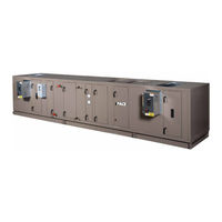
Indoor and Outdoor Air Handling Units
Brand:
Pace
| Category:
Air Handlers
| Size: 9.36 MB
Table of Contents
Table of Contents
5
Section 1 - General Information and Safety
13
Introduction
13
Warranty
13
Responsibility for Safety
13
Section 2 - Product Description
15
Typical Operation
15
Ventilation System
15
Economizer System (Typical)
15
FIGURE 1 - Cutaway Showing Segmented Construction
15
Heating and Cooling System
16
Cleaning
16
Hand Orientation
16
AHU Identification (ID)
16
FIGURE 2 - AHU and Coil Hand Identification
16
AHU ID Label
17
Skid ID Label
17
Segment ID Box
17
FIGURE 3 - AHU ID Label
17
FIGURE 4 - Skid ID Label
17
FIGURE 5 - Example of Segment ID Box
17
Shipped Loose Parts
18
Direction of Airflow
18
TABLE 1 - Definition of Segment Ids
18
Section 3 - Handling, Storage, and Installation
19
Delivery and Storage
19
Short Term
19
Long Term
20
Inspection, Damage, and Shortage
20
Check Doors and Latches
21
Indoor Ahus
21
Outdoor Ahus
21
Shipped Loose Parts
21
Lifting Weights
21
Moving the AHU
21
Rigging
21
FIGURE 6 - Metal Spacers on Doors
21
Using Fork Lift in Special Circumstances
22
Come-A-Longs (Power Pulls)
22
Proper Lifting with Shackles
22
FIGURE 7 - Recommended Lifting with Multiple Points
22
FIGURE 8 - Typical Come-A-Longs
22
FIGURE 9 - Proper Lifting with Shackle with Corner Connector Corners
22
Preparing the Site
23
Clearance for Outdoor Ahus
23
FIGURE 10 - Proper Lifting with Shackle at Lifting Lug
23
FIGURE 11 - Proper Lifting with Base Rail
23
Assembling the PACE Provided Curb
24
FIGURE 12 - Minimum Service Clearances
24
FIGURE 13 - Typical Curb Assembly
25
Clearance and Mounting for Indoor Ahus
26
FIGURE 14 - no Base Rail - Housekeeping Pad Required to Accommodate Trap Height
26
FIGURE 15 - no Housekeeping Pad - Base Rail Required to Accommodate Trap Height
26
FIGURE 16 - with Base or Base Rail and Housekeeping Pad
26
Installing Ceiling Suspended Ahus
27
FIGURE 17 - Ceiling Suspended AHU on Structural Steel
27
Tools Required to Install AHU
28
Installing Outdoor AHU
28
Single Piece Outdoor AHU
28
FIGURE 18 - Tools Needed to Assemble Shipping Splits
28
Multi-Piece Outdoor AHU
29
FIGURE 19 - Shipping Split Examples
29
FIGURE 20 - Shipping Split Examples Using Structural Steel Baserails
30
FIGURE 21 - Applying Gasket Square, Neoprene Gasket and Caulk to Raceway Split
30
Setting up the Sections
31
FIGURE 22 - Typical Come-A-Longs
31
FIGURE 23 - Electrical Connector (Not Connected)
31
FIGURE 24 - Electrical Connectors (Connected)
31
FIGURE 25 - Remove and Reposition Shipping Split Angle
31
Pulling the AHU Sections Together
32
FIGURE 26 - Come-A-Long Attached to a Section
32
FIGURE 27 - Bring Shipping Splits Together
32
FIGURE 28 - Applying Caulk to Seams
32
Installing Hood with Moisture Eliminators
33
Outdoor Air Temperature And/Or Humidity Sensors
33
FIGURE 29 - Installing Gaskets
33
FIGURE 30 - Corner Connector Hole Plug (P/N 021-19568-000)
33
Installing Indoor AHU
34
FIGURE 32 - Use Gasket (P/N 028-11883-010) at Shipping Split
34
FIGURE 31 - Installing Hood with Optional Moisture Eliminators
34
Installing an AHU with Expanded Cabinet
35
FIGURE 34 - Assembly of End Channel Shipping Split with an Expanded Cabinet
35
FIGURE 33 - Use Gasket (P/N 028-11873-010) to Door Frame at Shipping Split
35
Setting up and Pulling AHU Sections Together
36
FIGURE 35 - Come-A-Long Attached to a Section
36
FIGURE 36 - Remove Lifting Lugs in Expanded Cabinet
36
FIGURE 37 - Electrical Connector (Not Connected)
36
FIGURE 38 - Electrical Connectors (Connected)
36
FIGURE 39 - Remove and Reposition Shipping Split Angle
37
FIGURE 40 - Bring Shipping Splits Together
37
FIGURE 41 - Fasten Bottom Lifting Lugs
37
Installing a Tiered AHU
38
FIGURE 42 - Corner Connector Hole Plug (P/N 021-19568-000)
38
FIGURE 43 - Tiered AHU
38
FIGURE 44 - Second Tier Tie-Down Fastener Pack (P/N 386-03419-000)
38
FIGURE 45 - Apply Gaskets to Top Panel on Bottom Tier
38
FIGURE 46 - Guide Brackets Together
39
FIGURE 47 - Lights Tier Transition Drawing
39
Assembling the End Channel Shipping Split
40
FIGURE 48 - Assembling the End Channel Shipping Split with Energy Recovery Wheel
40
Installing Damper Actuator
41
FIGURE 49 - Installing the Direct Coupled Actuator
41
Installing Multi-Zone (MZ) Dampers
42
FIGURE 50 - Installing MZ Damper
42
Installing Field Supplied MZ Damper Actuators
43
Shipped Loose Parts
43
FIGURE 51 - Damper Shaft Extension Kit (P/N 026-33715-002)
43
FIGURE 52 - Second Tier Tie-Down Fastener Pack (P/N 386-03419-000)
43
FIGURE 53 - Bottom Raceway Shipping Split Fastener Pack (P/N 386-03418-000)
43
Pipe Chase, Hoods and Seam Caps
44
FIGURE 54 - Base Rail Shipping Split Fastener Pack (P/N 386-03417-000)
44
FIGURE 55 - Top Raceway Bracket Assembled (P/N 386-04747-000)
44
FIGURE 56 - Neoprene Gasket - 1/4 In. X 2 In. X 25 Ft (P/N 028-15954-010)
44
FIGURE 57 - Neoprene Gray Gasket - 1/4 in X 3/4 in X 35 Ft (P/N 028-11873-010) for Door
44
FIGURE 58 - Phillips Hex Head Screw (P/N 021-32268-011) for Indoor Unit Seam Cap
44
FIGURE 59 - Hex Head Screw for Outdoor Roof Seam Cap, Pipe Chase, and Rain Hood - 1/4 In-14 X 1 in
44
FIGURE 60 - Butyl Tape - 3/16 in X 3/4 in X 40 Ft (P/N 013E-03327-010)
44
FIGURE 61 - Polyurethane Caulk (Grey: P/N 021-19568-000; Champagne: P/N 013-03317-040) for Pipe Chase
45
FIGURE 62 - Roof Seam Cap (Assembled)
45
FIGURE 63 - Pipe Chase, Trim Angle, and Cover
45
FIGURE 64 - Hood
45
Additional Parts
46
FIGURE 65 - Damper Shaft Extension Kit (P/N 026-33715-002)
46
FIGURE 66 - Corner Connector Hole Plug (P/N 021-19568-000) (8)
46
FIGURE 67 - Touch-Up Spray - 12 Oz. (P/N 013-03322-000)
46
FIGURE 68 - Shipping Split Corner Gasket - 3.5 X 3. 5 (P/N 028-11883-010)
46
FIGURE 69 - Spare Fan Belt
46
FIGURE 70 - Conduit (P/N 025-39024-001) and SJO Cord (P/N 025-35746-001)
46
Air Filters
47
Maintaining and Replacing Filters
47
FIGURE 71 - Typical Filter Types
47
FIGURE 72 - Filter Latches
48
TABLE 2 - Koch Filter Clips - Single Filter Application
49
TABLE 3 - Koch Filter Clips - Pre-Filter / Final Filter Application
49
TABLE 4 - AAF Clips for Filter Frames - Single Filter Application
49
Filter Installation Installing a 2 In. Pleated Filter
50
FIGURE 73 - Correctly Installed Latch Pin (P/N 026-35788-702)
50
TABLE 5 - AAF Pre-Filter/Final Filter Application
50
Installing a 4 In. Pleated Filter
51
FIGURE 74 - Fully Installed Filter
51
FIGURE 75 - Correctly Installed Latch Pin (P/N 026-35788-604)
51
FIGURE 76 - Place End of Latch over Filter Frame
51
Installing a Single Headered (SH) Filter
52
Installing a 2 In. Pre-Filter Combined with a SH Final Filter
52
FIGURE 77 - Correctly Installed Cartridge Filter
52
FIGURE 78 - Correctly Installed Latch Pin (P/N 026-35788-604)
52
FIGURE 79 - Correctly Installed Cartridge with Pleats
52
Installing a Multi-Cell SBM Double Headered (DH) Filter
53
FIGURE 80 - Correct Use of Knockouts
53
FIGURE 81 - Correct Latchout/Knockout Configuration
53
FIGURE 82 - Frame with Four Latches Installed on the Sides
53
FIGURE 83 - Spring Latch Pulled and Fastened in Filter Hole
53
Installing a 2 In. and 4 In. Pre-Filter Combined with a DH Final Filter
54
FIGURE 84 - Correct Latchout/Knockout Configuration (P/N 026-35788-612)
54
FIGURE 85 - Spring Latch Pulled and Fastened in Filter Hole
54
FIGURE 86 - Installing Pre-Filter Latch
54
FIGURE 87 - Position Pre-Filter in Front of Final Filter
55
FIGURE 88 - Spring End of Latch
55
FIGURE 89 - Completed Assembly
55
Hepa Filters
56
Koch HEPA Filter Frame
56
FIGURE 90 - Installation of Koch HEPA Filters
56
Welded Bevel Seal Frame
57
Visual Control Filter Clamps
57
HEPA Filter Applications
57
FIGURE 91 - Koch HF
57
FIGURE 92 - Hepa Filter (Cross Section)
57
FIGURE 94 - Installing Hepa Filter
58
FIGURE 93 - Visual Control Filter Clamps
58
TABLE 6 - Visual Control Filter Clamps for HEPA Filters
58
FIGURE 95 - Installing Welded Bevel Seal Filter
59
Filling Inertia Fan Base
60
Thrust Restraint Replacement and Adjustment
60
Rear Discharge Orientation
60
FIGURE 96 - Supply Fan Restraint
60
FIGURE 97 - Thrust Restraint Assembly
61
FIGURE 98 - Plenum Fan Thrust Restraint
61
Aligning Sheaves
62
Using a Straightedge
62
Using a String
62
Belt Replacement Tensioning and Sheave Alignment for Top Mount
63
FIGURE 99 - Alignment Using Straight Edge
63
FIGURE 100 - Alignment Using String
63
FIGURE 101 - Sheave Angular Misalignment
64
FIGURE 102 - Motor Base Lowered
64
FIGURE 103 - Sheave Angular Alignment
64
FIGURE 104 - Sheave Angular Misalignment
64
Steam Humidifier
65
UVC Emitter Lamps
65
Two Types of Lamps
65
FIGURE 105 - V-Max Grid Lamps
65
FIGURE 106 - Installing V-Mod Lamp
65
FIGURE 107 - Installing V-Max Grid Lamps
65
FIGURE 108 - UV Control Panel Wiring (8 Amps)
67
FIGURE 109 - UV Control Panel Wiring (Greater than 8 Amps)
68
Air Measuring Device Connections
70
Air Measuring at the Fan Inlets
70
Air Measuring at Unit Outside Air Inlets
70
FIGURE 110 - High and Low Connections for an in Fan Air Monitoring System
70
FIGURE 111 - High and Low Connections and Associated Tubing for Fan Mounted Air Monitoring System
70
FIGURE 112 - Port Locations for Fan Mounted Air Monitoring System
70
Back Draft Dampers for Dual Fans and Fan Arrays
71
Installing the Pipe Chase
71
Tools and Materials
71
Preparing Pipe Chase for Installation
71
FIGURE 113 - Counterbalance Locked into Place for Shipping
71
FIGURE 114 - Counterbalance Unlocked for Start-Up
71
Apply Gaskets
72
Attach Pipe Chase
72
FIGURE 117 - Install Pipe Chase Base Rail to AHU Base Rail
72
FIGURE 115 - Install Gasket under Roof Overhang
72
FIGURE 116 - Apply Gasket to Pipe Chase
72
FIGURE 118 - Install Flanges
72
Seal Pipe Chase to AHU
73
Install Cover Angles
73
FIGURE 119 - Apply Caulk to Base Rail
73
FIGURE 120 - Apply Caulk between Pipe Chase and AHU
73
FIGURE 121 - Install Pipe Chase to Roof
73
Install Base Rail Covers (if Applicable)
74
FIGURE 122 - Install Cover Angle
74
FIGURE 123 - Position Cover Angle Properly
74
FIGURE 124 - Properly Install Screws
74
FIGURE 125 - Apply Base Rail Cover
74
Installing External Vent Piping for Outdoor Ahus
75
Condensate Drain Arrangement
75
FIGURE 126 - Gas Furnace Fuel Venting System
75
FIGURE 127 - Gas Furnace Condensate Drain Trap
76
TABLE 7 - TSP and Drain Trap
76
General Electrical Information
77
Power Connections
77
Single Point Power
77
FIGURE 128 - Single Point Power Connection
77
Motors for Supply, Return, and Exhaust Fans
78
Wiring the Energy Recovery Wheel
78
FIGURE 131 - Access Electrical Box
78
FIGURE 129 - Typical Motor Data/Name Plate
78
FIGURE 130 - Another Typical Motor Data/Name Plate
78
FIGURE 132 - Typical Power Wiring of Energy Recovery Wheel
78
Wiring the Gas Heat Device
79
FIGURE 133 - Gas Burner Component Locations
79
FIGURE 134 - Main Power and Control Panel with Cover Open
79
Wiring the Electric Heat Device
80
Power Options
80
Disconnect Switch Options
80
FIGURE 135 - Typical Electrical Heat Control Panel Interior Wiring and Components
80
FIGURE 136 - Typical Field and Power Connections
80
Control Options
81
Installing Electrical Heat Option
81
FIGURE 137 - Pressure Probe Direction
82
FIGURE 138 - Air Flow Switch Connections
82
TABLE 8 - Maximum Current
83
Electric Humidifier
84
Humidifier
84
FIGURE 139 - Layout of Typical Humidifier Panel
84
FIGURE 140 - Supply Power Knockouts
84
FIGURE 141 - Humidifier Points
84
Field Penetrations for Piping and Electrical Connections
85
Tools Required
85
Material Required
85
Procedure
85
FIGURE 142 - Penetrations and Grommet Details
86
Lights for Ahus
87
Piping Connections
87
FIGURE 143 - AHU with Lights Tier Transition Drawing
87
FIGURE 144 - Pipe Chase Enclosure
87
Coil Piping
88
Staggered Coils
88
FIGURE 145 - Factory Coil Connections
88
FIGURE 146 - Staggered Coil - Angled Wall
88
Hot and Chilled Water Coils
89
FIGURE 147 - Split Coil - Opposite Side Connections
89
FIGURE 148 - Chilled Water Coil Connections Example - (Not for Construction)
89
FIGURE 149 - Hot Water Piping with 2-Way Valve Example (Not for Construction)
90
FIGURE 150 - Hot Water Piping with Diverting Valve Example (Not for Construction)
90
Water Treatment
91
Freeze Protection
91
Steam Coils
91
Steam Distributing Coils
91
Steam Control
91
Steam Traps
91
FIGURE 151 - Steam Coil Piping Arrangements
92
Drains and Traps
93
Condensate Drain Piping
93
FIGURE 152 - Drain Trap Showing Water Location for Draw through Operation
93
FIGURE 153 - Trap Detail for Drain Pan in Negative Environment (Draw Through)
93
FIGURE 154 - Trap Detail for Drain Pan in Positive Environment (Blow Through)
93
Elevating AHU for Gravity Floor Drain Connections
94
Duct Connections
94
Duct Connection Guidelines
94
Flanged Duct or Sleeves
94
FIGURE 155 - Combining Drain Lines
94
FIGURE 156 - Recommended Discharge Duct Arrangement When Turns Are Required
94
Raw or Straight Edge Duct or Sleeves
95
Sound and Vibration Transmission
95
Installing Top Discharge Outdoor AHU Duct
95
Installing Front and Rear Discharge Outdoor AHU Duct
95
FIGURE 157 - Duct Arrangement for Flange and Raw Edge Ducts
95
FIGURE 159 - Roof to Duct Installation (Horizontal Discharge)
96
FIGURE 158 - Duct Penetration of Roof
96
Vertical Tube Integral Face and Bypass (VIFB) and Integral Face and Bypass (IFB)
97
Shipping Bolts (VIFB Only)
97
Piping Suggestions
97
Flexible Connectors (VIFB Only)
97
Freezing Conditions
97
FIGURE 160 - IFB Coil (Horizontal Tubes Available with Steam and Hot Water)
98
FIGURE 161 - VIFB Coil (Face-Mounted Actuator Shown)
98
FIGURE 162 - Hot Water Piping Schematic for 2-Row Coil VIFB
98
FIGURE 163 - Hot Water Piping for IFB
99
FIGURE 164 - Steam Piping for VIFB
100
Refrigeration
101
DX Direct Expansion Coils
101
FIGURE 165 - Typical Piping and Sundries at the DX Coil
102
FIGURE 166 - DX Coil Circuiting Types
102
Available Coil Arrangements
103
FIGURE 167 - Non-Stacked Coil Design (Special Quote)
103
FIGURE 168 - Non-Stacked Coil Design (Standard)
103
FIGURE 169 - Stacked Coil Design (Standard)
104
FIGURE 170 - Stack Coil Designs (Special Quote)
104
Thermostatic Expansion Valves (TXV)
105
Hot Gas Bypass (HGBP)
105
DX Coil Circuiting and Staging
105
FIGURE 171 - Stacked Coil Circuiting
105
FIGURE 172 - One Coil Circuit Per Refrigerant Circuit
105
FIGURE 173 - Two Coil Circuit Per Refrigerant Circuit
105
Advantages of Multiple Control Stages
106
Maintaining Adequate Airflow
106
FIGURE 174 - Three Compressor Unit
106
FIGURE 175 - Six Compressor Unit
106
VAV Systems
107
Advertisement
Advertisement
Related Products
Pace PAO
Pace px013anc
Pace PX051AEI
Pace PH 100
Pace PH 100E
Pace PXD10ANI
Pace PX031ANI
Pace PX022ANx
Pace PX001BNM
Pace PROGRAMMABLE THERMOFLO
Pace Categories
Set-top boxes
Soldering Gun
DVR
Gateway
Power Tool
More Pace Manuals
Login
Sign In
OR
Sign in with Facebook
Sign in with Google
Upload manual
Upload from disk
Upload from URL