Table of Contents
Advertisement
Quick Links
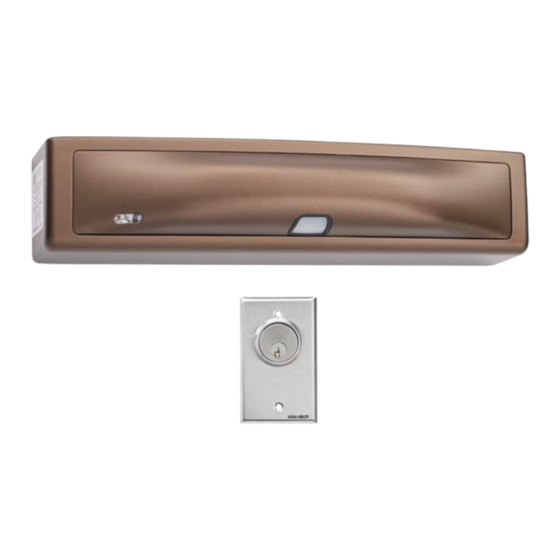
DEM680E Series Delayed Egress
Magnalock
Installation & Operating Instructions
Product Components
A Magnalock & Mounting Bracket
B Strike Housing
C Strike Plate Assembly
D Wall Mounted Key Switch
Installation Hardware Pack Contents
I #14 X 3" Type A Phillips
Pan Head Screw (4)
J Threadlocker Packet
K WOOD DOORS: #6 X
1/2" Phillips Flat Head
Type A Steel Screw (6)
L METAL DOORS: 6-32 X
3/8" Phillips Flat Head
Type F Steel Screw (6)
NOTE: Hardware is provided for various installations.
There will be leftover parts depending on the type of installation.
Specifications
Dimensions
•
Height: 2.50" [64 mm]
•
Depth: 2.56" [65 mm]
•
Length: 11.50" [292 mm]
Certifications
•
UL 10C Fire Rated, 1 Hour
•
CAN/ULC-S104 Fire Door Conformant
•
UL 294
•
UL Tested Ratings: Endurance:
100,000 cycles
•
ANSI/BHMA A156.23, Grade
2; E18501 Compliant
•
California State Fire Marshal Listed
•
NFPA 101
IMPORTANT: UL 294 compliance requires that the locking device be powered by a UL
294 (ALVY) or UL 603 (APHV) listed power supply and shall be installed in accordance
with the following UL and National Standards: NFPA 70 – National Electrical Code.
®
with EcoMag
E Settings Labels
F Sex Bolt & Tapered Washer
G Template Pins
H NFPA Door Label
M #12 X 1-1/2" Type A Phillips
Pan Head Screw (4)
N Rivet Nut Install Tool
O 1/4-20 X 1" Phillips Pan
Head Screw (2)
P 1/4-20 Rivet Nut (2)
Q 3/16" Hex Key
Electrical
•
Magnalock Minimum Current Draw
(±10%)
95 mA at 12 VDC
65 mA at 24 VDC
•
Magnalock Maximum Current Draw
(±10%)
575 mA at 12 VDC
315 mA at 24 VDC
Static Holding Force
•
1,200 lbs [544kg]
Operating Temperature
•
32˚ to 120˚F [0˚ to 49˚C]
•
Indoor use only
Technology
™
IMPORTANT This Magnalock requires calibration upon installation.
Diagram 1 Product Components
B
C
D
H
I
M
A
E
G
F
J
K
L
O
Q
N
P
1 of 12
Advertisement
Table of Contents

Related Manuals for Assa Abloy SECURITRON DEM680E Series


Summary of Contents for Assa Abloy SECURITRON DEM680E Series
- Page 1 DEM680E Series Delayed Egress Magnalock ® with EcoMag Technology ™ Installation & Operating Instructions Product Components IMPORTANT This Magnalock requires calibration upon installation. Diagram 1 Product Components A Magnalock & Mounting Bracket E Settings Labels B Strike Housing F Sex Bolt & Tapered Washer C Strike Plate Assembly G Template Pins D Wall Mounted Key Switch...
- Page 2 Performing a Diagram 2 Assessing the installation site 2-1/4" from door to trailing pre-installation survey edge of bracket 1-1/8" Bracket Before installing the Magnalock, determine and Mounting 1-11/16" from assess the mounting location for the following: Surface door to center of bracket slots •...
- Page 3 Diagram 6 Marking the wire feed-through hole MARK the frame through the two (2) oblong (slotted) bracket mounting holes (see Diagram 5). 5/16" MARK the frame for a wire feed-through hole at the end closest to where the wire run will be accessed and ensure the hole marking is centered at least 5/16”...
- Page 4 Installing the strike Diagram 11 Marking the Diagram 12 Drilling the sex strike housing mounting hole on the door locations from the inside bolt hole from the outside With the door closed, ALIGN the strike housing with the template pins as indicated on the strike housing.
- Page 5 Mounting the Diagram 16 Mounting the Diagram 17 Marking the back Magnalock to the bracket edge of the mounting bracket Magnalock and aligning to the strike plate SLIDE the Magnalock assembly to fully engage the lock chassis to the mounting bracket. Install one of the three screws through one of the top chassis holes and into the mounting bracket to temporarily secure the Magnalock (see Diagram 16).
- Page 6 MAGNALOCK ELECTRICAL INSTALLATION Pulling the wiring Diagram 24 Location of J1 and J4 terminals NOTE: End-user and installer must comply with fire and building codes. PULL wires/cables through the wire feed- through hole(s) drilled in the frame. INSTALL the provided wall- mounted switch if necessary.
- Page 7 Diagram 29 Jumper Locations Table 1 Jumper Settings H2 (BOND) Jumpers Position Selection Function/Description Factory Default H3 (DPS) JP3 (EXT INIT) H2 (BOND) Normally Normally closed circuit – opens closed (NC) when BOND registers secure. Normally closed Normally Normally open circuit – closes open (NO) when BOND registers secure.
-
Page 8: Configuration Settings
Delayed Egress status LEDs Diagram 31 LED location The two LEDs shown display the following Delayed Egress states. GREEN STATE Unlocked Bypass Egress Alarm Locked Documenting the Diagram 32 System settings configuration settings Indicate the settings on the adhesive-backed labels included with the Magnalock (see Diagram 32). -
Page 9: Initial Calibration
Initial calibration Diagram 34 Calibration button NOTE 1: If calibration does not proceed according to the instructions below, please see the troubleshooting section at the end of the manual. NOTE 2: Initial calibration can be performed with a 12-V battery for Calibration Button installations in facilities that do not yet have commercially-available power. -
Page 10: Alarm Function
MAGNALOCK OPERATIONAL TESTS Test 1 – Verifying Diagram 36 Indicator light displays correct startup The DEM680E should be calibrated with a non-zero nuisance delay setting. With the door closed, the LED should be GREEN, indicating that it is active (see Diagram 36). Diagram 37 •... -
Page 11: Troubleshooting Guide
Troubleshooting Guide TROUBLE INDICATOR POSSIBLE CAUSES POSSIBLE SOLUTIONS • Two bond sensor failures* • Ensure bond sensor connectors are properly seated Solid RED • Supply voltage < 8.5 VDC • Check power supply voltage • Two bond sensor failures* • Ensure bond connectors are properly seated •... -
Page 12: Warranty
Patent pending and/or patent www.assaabloydss.com/patents securitron.com | 800 626 7590 Copyright © 2022, Hanchett Entry Systems, Inc., an ASSA ABLOY Group company. All rights reserved. Reproduction in whole or in part without the express written 10027 S. 51st Street Phoenix, AZ 85044 USA permission of Hanchett Entry Systems, Inc.
Need help?
Do you have a question about the SECURITRON DEM680E Series and is the answer not in the manual?
Questions and answers