Table of Contents
Advertisement
Quick Links
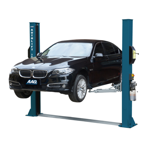
2 POST HOIST
AutoLift AL-6254A
Asymmetric 2 Post Baseplate Vehicle Hoist
3800Kg Maximum Lifting Capacity
Design Registration Approval Number: WAH19926
Design Code: AS1418.9-1996
Note: While all due care and attention has been taken in the preparation of this document, Advance AutoQuip shall not be liable for any inaccuracies or omissions
Ph: 08 9279 1663 | Fax: 08 9279 1667 | E: sales@aaq.net.au | W: www.aaq.net.au
INSTALLATION MANUAL & OPERATION
INSTRUCTIONS
- READ THE ENTIRE CONTENTS OF THIS MANUAL BEFORE
INSTALLATION AND OPERATION. BY PROCEEDING YOU AGREE THAT
YOU FULLY UNDERSTAND AND COMPREHEND THE FULL CONTENTS
OF THIS MANUAL. FORWARD THIS MANUAL TO ALL OPERATORS.
FAILURE TO OPERATE THIS EQUIPMENT AS DIRECTED MAY CAUSE
Specifications subject to change without notice.
which may occur therein
Advance AutoQuip
2 McDonald Crescent | Bassendean WA 6054
INJURY OR DEATH.
READ FIRST
DO NOT use the
machine until you read
and understand all the
dangers, warnings and
cautions in this manual.
Advertisement
Table of Contents

Related Manuals for AAQ AL-6254A


Summary of Contents for AAQ AL-6254A
- Page 1 Note: While all due care and attention has been taken in the preparation of this document, Advance AutoQuip shall not be liable for any inaccuracies or omissions which may occur therein Advance AutoQuip 2 McDonald Crescent | Bassendean WA 6054 Ph: 08 9279 1663 | Fax: 08 9279 1667 | E: sales@aaq.net.au | W: www.aaq.net.au...
- Page 2 Installation, Operation and Parts Manual AutoLift AL-6254 INDEX 1. Important safety instructions… ................2‐3 1.1 Important notices 1.2 Qualified personnel 1.3 Danger notices 1.4 Training 1.5 Warning signs 2. Overview of the hoist ....................4 2.1 General descriptions 2.2 Technical data 2.3 Construction of the hoist 3. Installation instructions… ..................5‐10 3.1 Preparations before i nstallation 3.2 Precautions for ...
-
Page 3: Important Safety Instructions
Installation, Operation and Parts Manual AutoLift AL-6254 IMPORTANT SAFETY INSTRUCTIONS 1.1 Important notices Advance AutoQuip will offer one‐year's quality warranty for the whole machine,during which any quality problem will be properly solved to the user's satisfaction. However, we will not take any responsibility for whatever bad consequence resulted from improper installation and operation, overload running or unqualified ground condition. This 2‐posts hoist is specially designed for lifting motor vehicles that weighs within its outmost lifting capacity. Users are not allowed to use it for any other purposes. Otherwise, we, as well as our sales agency, will not bear any responsibility for accidents or damages of the hoist. Make sure to pay careful attention to the label of the lifting capacity attached on the hoist and never try to lift cars with its weight beyond. Read this manual carefully before operating the machine so as to avoid economic loss or personnel casualty incurred by wrong operation. Without our professional advice, users are not permitted to make any modification to the control unit or whatever mechanical unit. 1.2 Qualified personnel 1.2.1 Only these qualified staff, who have been properly trained, can operate the hoist. 1.2.2 Electrical connection must be done by a competent electric i a n . 1.2.3 People who are not concerned are not allowed in the lifting area. 1.3 Danger notices 1.3.1 Do not install the hoist on any asphalt surface. 1.3.2 Read and understand all safety warnings before operating the hoist. 1.3.3 The hoist, if is not specially designed upon customer’s request, is not fit for outdoor use. 1.3.4 Keep hands and feet away from any moving parts. Keep feet clear of the hoist when lowering. 1.3.5 Only these qualified people, who have been properly trained, can operate the hoist. 1.3.6 Do not wear unfit clothes such as large clothes with flounces, tires, etc, which could be caught by moving parts of the hoist. 1.3.7 To prevent evitable incidents, surrounding areas of the hoist must be tidy and with nothing unconcerned. ... -
Page 4: Warning Signs
Installation, Operation and Parts Manual AutoLift AL-6254 Attention: For environment protection, please dispose the disused oil in a proper way. 1.5 Warning signs All safety warning signs attached on the machine are for the purpose of drawing the user’s attention to safety operation. The labels must be kept clean and need to be replaced when they are worn‐out or have dropped. Read the explanations of the labels carefully and try to memorize them. ... -
Page 5: General Descriptions
Installation, Operation and Parts Manual AutoLift AL-6254 OVERVIEW OF THE HOIST 2.1 General descriptions This two‐ post hoist is composed of posts, carriages, lifting arms, cylinders and motor unit, etc. The hoist is driven by an electro‐hydraulic system. The gear pump delivers hydraulic oil to oil cylinders and pushes upwards its piston. The piston drives the chain to raise the carriage and the lifting arms. During the lifting process, the safety paws will automatically and firmly lock on the safety ladder. Therefore, no dropping will happen in case of hydraulic system failure. Safety structure: Lock Cover Locking Leaver Arm Lock 2.2 Technical data Model Lifting capacity Lifting time Lifting height Height Width Width between posts 3800kg 50 Sec 1930mm 3436mm 2850mm AL6254 2424mm MAX. MIN. FOUNDATION DIMENSIONS QUALITY OF REACTION ON... -
Page 6: Preparations Before Installation
Installation, Operation and Parts Manual AutoLift AL-6254 3.1 Preparations before installation 3.1.1 Tools and equipments needed Appropriate lifting equipment Anti‐abrasion 32 grade hydraulic oil. Rotary Hammer Drill with 18mm masonary drill bit. Chalk and tape measure, magnetic level. Sockets and open wrenches, a set of inside hex wrenches, star and straight screw d rivers. Hammer, 4pounds, sharp nose pliers, Ф14 Ф17,Ф18,Ф22 socket spanners。 3.1.2 List for parts checking ‐‐‐Annex 1(Packing list) Unfold the package and check if any parts missed as per Annex 1. Please contact us in case any parts are missing, but do note if you do not contact us and insist installing despite the lack of some parts, Advance AutoQuip as well as our dealers will not bear any responsibility for this and will charge for any parts subsequently demanded by the buyer. 3.1.3 Ground conditions The hoist should be fixed on a flat, level and solid concrete surface with its strength more than 3000psi, tolerance of flatness less than 5mm and minimum thickness of 150mm. In addition, newly laid concrete ground must undergo more than 28 days cure time. 3.2 Precautions for installation 3.2.1 Make sure the two posts stand parallel. NOTE: once both posts are firmly bolted to the concrete floor, use shims to lean the columns outwards by 25mm to allow for deflection. 3.2.2 Joints of oil hose and steel cable must be firmly connected in order to avoid looseness of steel cable and leakage of oil. 3.2.3 All bolts should be firmly screwed up. ... - Page 7 Installation, Operation and Parts Manual AutoLift AL-6254 1.Unfold the package and decide on which post the power unit will be mounted. 2.. Draw an outline of the base plate on the ground with chalk and ascertain the position for the post. Step 5: Erect and secure first post, power side post (the post on which the control box and pump assembly will be mounted) first and then the other post. 1. Using the base plate as a template, use a masonary drill to drill the holes. 2. Remove thoroughly the debris and dust in holes and ascertain that the posts stay right upon the circle previously marked by chalk. 3. Secure the second post as per step, 1, 2. NOTE: Torque all anchor bolts to 120 ft lbs. Step 6: Fix the base plate & channel plate. Raise both carriages about 800mm from the ground then rest on the safety locks. Place the channel plate between the two base plates of the post. channel plate Step 7: Connect steel wire ropes. 1. Route and fix according to the following diagram of steel wire ropes connection. 2. Raise carriages on both sides approximately 800mm above the ground. Carriages must be at the same height from the floor. 3. Make sure that the mechanical safety locks on each post are fully engaged before attempting to route the wire ropes. 4. After fixing the ropes, adjust the ropes on both sides to the same tension which could be judged when the ratchet sound emits during lifting process. Make adjustments after trial run.
- Page 8 Installation, Operation and Parts Manual AutoLift AL-6254 5. Grease inside of each colum corners with GP grease. THIS MUST BE DONE. Step8: Mount the power unit onto the power side post. ...
- Page 9 Installation, Operation and Parts Manual AutoLift AL-6254 Step 9. Connect oil hoses NOTE: make sure the connectors and hose are clean. ...
- Page 10 Installation, Operation and Parts Manual AutoLift AL-6254 Step 10: Connect electrical wires. Attention: Only licensed electricians are allowed to carry out electrical connection. Mount the control box on to the power side post. top limit switches motor cable connect to the control box Connect the limit switch inside the power‐side post. Connect motor wire and power suppply cable including the top limit switch wire to the control box . Step 11: Install lifting arms. Install the lifting arms on the carriage by 38mm pins. NOTE: Long arms are to the rear of the vehicle. Step 12: Fill Oil Tank. Oil tank volumn is 10L. Normal work should have 80% oil inside the tank. Usually the hoist needs 13 litres of hydraulic oil. Fill about 10 litres into the oil tank then run the hoist up and down 2 or 3 times. Refill the remainder 3 litres of oil. It is suggested to use 32#anti‐abrasion hydraulic oil. ...
- Page 11 Installation, Operation and Parts Manual AutoLift AL-6254 POWER SIDE POST OTHER POST Step 13: Locking Mechanism. Do refer to the operation instructions in advance and keep in mind that NO vehicle is to be placed on the hoist during trial run. 1. Route lock cable and conduit down the inside of the motor post down to bottom channel plate, then over to the inside of the next column, then up to the lock assembly. 2. Loop the pull cable over the pull handle latch bolt then lock off with barrel union. Apply tension to lock cable on opposite post lock latch bracket then lock off with barrel union. 3. Check mechanical locks for correct engagement by releasing the lock during the running process. Adjust by tightening the wire cable on the lock latch. NOTE: Hoist must be rested on locks during adjustments. Step 14: Connect Power and do a trial run. 1. Assure all the connections are in good condition and connect the power supply. Step 15: Fix feet protection fenders, door‐opening protections, tool trays and lock covers. 3.4 Items to be checked after installation. S/N Check items YES NO 1 Are the posts vertical to the floor? 2 Are the two posts paralleled? 3 Is the oil hose well connected? 4 ...
- Page 12 Installation, Operation and Parts Manual AutoLift AL-6254 OPERATION INSTRUCTIONS 4.1 Precautions 4.1.1 Check all the joints of oil hose. Only when there is no leakage, the hoist can be o perated. 4.1.2 DO NOT use the hoist if the safety device malfunctions. 4.1.3 Make sure the vehicle is evenly balanced on the hoist. Otherwise, Advance AutoQuip as well as our dealers will not bear any responsibility for any consequence resulted thereby. 4.1.4 Operators and other personnel should stand in a safe area during lifting and lowering process. 4.1.5 When the hoist is raised to the desired height, switch off the power at once to prevent any operation by other personnel. 4.1.6. Make sure the safety lock is engaged before working under the vehicle and no persons or objects are under the vehicle during lifting and lowering process. 4.2 Flow chart for operation Raising Lowering Start Start ...
-
Page 13: Troubleshooting
Installation, Operation and Parts Manual AutoLift AL-6254 TROUBLE SHOOTING ATTENTION: If the trouble could not be fixed by the troubleshooting guide, please do not hesitate to contact us for help .We will offer our support and service at the earliest possible time. Please email supporting and detailed or pictures to us. TROUBLES CAUSE SOLUTION Abrasion exists on insider surface of the posts. Grease the inside of the post. Abnormal noise Trash in the post. Clear the trash The wire connection is loose. Check and make a good connection. Motor does not run and The motor is blown. Replace it. will not rise Connect it or adjust or replace the limit The limit switch is damaged or the wire connection is loose. switch. The motor run reversely. Check the wire connection. Overflow valve is loose or jammed. Clean or adjust it. Motor runs but will not The gear pump is damaged. Replace it. raise Oil level is too low. Add oil. The oil hose became loose or dropped off. Tighten it. The cushion valve became loose or jammed. Clean or adjusts it. ... -
Page 14: Maintenance
Installation, Operation and Parts Manual AutoLift AL-6254 The hydraulic oil is too hot ( above 45°). Change the oil. The seal of the cylinder is abraded. Replace the seal. Inside surface of the posts is not well greased. Add grease. The throttle valve jammed. Clean or replace. The hydraulic oil is dirty. Change the oil. Lowering too slow The anti‐surge valve jammed. Clean it. The oil hose jammed. Replace it. The steel cable is No grease when installation or out of lifetime Replace it. abraded MAINTENANCE Easy and low cost routine maintenance can ensure the hoist work normally and safely. Following are requirements for routine maintenance. Frequency of routine maintenance is determined by working condition and frequency. The following parts need lubrication. S/N Description 1 Up pulley 2 ... - Page 15 Installation, Operation and Parts Manual AutoLift AL-6254 ∙Check arm locks for correct engagment. 6.2 Weekly checking items ∙Check all moving parts. ∙Check the working conditions of safety parts. ∙Check the amount of oil left in the oil tank when at full height. Otherwise the oil is too low and will need to be topped up. ∙Check whether expansion bolts are firmly screwed. 6.3 Monthly checking items ∙Check whether expansion bolts are firmly screwed. ∙Check the tightness of the hydraulic system and screw firm the joints if it leaks. ∙Check the lubrication and abrasion circumstance of axial pins, carriages, lifting arms and other related parts and replace in time with new ones if they failed to work well. ∙Check the lubrication and abrasion circumstance of steel cable. 6.4 Yearly checking items ∙Empty the oil tank and check the quality of hydraulic oil. ∙Wash and clean the oil filter. If the above maintenance suggestions are strictly followed, the hoist will always keep in a good working condition and meanwhile accidents could be avoided to a large extent. ANNEX Annex 1, Packing List of the whole hoist S/N Name Drawing# Property Qty FL-8224D-A1 1 Power‐side post Assembly 1 FL-8224D-A2 2 ...
- Page 16 Installation, Operation and Parts Manual AutoLift AL-6254 -A13 FL-8224 19 Rod of the chain protection cloth Zinc‐plating 4 FL-8224-A7-B3 20 Lifting tray Assembly 4 FL-8224-A7-B4 21 Long arm fender Powder‐coating 2 FL-8224-A8-B3 22 Short arm fender Powder‐coating 2 -A15 FL-8224 23 Height adapter Zinc‐plating 4 FL-8224-A12 24 Shaft Zinc‐plating 4 FL-8224-A11 25 ...
- Page 17 I I n n s s t t a a l l l l a a t t i i o o n n , , O O p p e e r r a a t t i i o o n n a a n n d d P P a a r r t t s s M M a a n n u u a a l l A A u u t t o o L L i i f f t t A A L L - - 6 6 2 2 5 5 4 4 Annex2, Overall diagram ...
- Page 18 I I n n s s t t a a l l l l a a t t i i o o n n , , O O p p e e r r a a t t i i o o n n a a n n d d P P a a r r t t s s M M a a n n u u a a l l A A u u t t o o L L i i f f t t A A L L - - 6 6 2 2 5 5 4 4 Annex3, Floor plan ...
- Page 19 I I n n s s t t a a l l l l a a t t i i o o n n , , O O p p e e r r a a t t i i o o n n a a n n d d P P a a r r t t s s M M a a n n u u a a l l A A u u t t o o L L i i f f t t A A L L - - 6 6 2 2 5 5 4 4 Annex4, Wiring diagram ...
-
Page 20: Three Phase
I I n n s s t t a a l l l l a a t t i i o o n n , , O O p p e e r r a a t t i i o o n n a a n n d d P P a a r r t t s s M M a a n n u u a a l l A A u u t t o o L L i i f f t t A A L L - - 6 6 2 2 5 5 4 4 Three phase... - Page 21 I I n n s s t t a a l l l l a a t t i i o o n n , , O O p p e e r r a a t t i i o o n n a a n n d d P P a a r r t t s s M M a a n n u u a a l l A A u u t t o o L L i i f f t t A A L L - - 6 6 2 2 5 5 4 4 2 2 0 0 ...
- Page 22 I I n n s s t t a a l l l l a a t t i i o o n n , , O O p p e e r r a a t t i i o o n n a a n n d d P P a a r r t t s s M M a a n n u u a a l l A A u u t t o o L L i i f f t t A A L L - - 6 6 2 2 5 5 4 4 Annex5, Hydraulic working system ...
- Page 23 I I n n s s t t a a l l l l a a t t i i o o n n , , O O p p e e r r a a t t i i o o n n a a n n d d P P a a r r t t s s M M a a n n u u a a l l A A u u t t o o L L i i f f t t A A L L - - 6 6 2 2 5 5 4 4 Annex 6,Separate diagrams for the hoist S/N ...
- Page 24 I I n n s s t t a a l l l l a a t t i i o o n n , , O O p p e e r r a a t t i i o o n n a a n n d d P P a a r r t t s s M M a a n n u u a a l l A A u u t t o o L L i i f f t t A A L L - - 6 6 2 2 5 5 4 4 S/N ...
- Page 25 I I n n s s t t a a l l l l a a t t i i o o n n , , O O p p e e r r a a t t i i o o n n a a n n d d P P a a r r t t s s M M a a n n u u a a l l A A u u t t o o L L i i f f t t A A L L - - 6 6 2 2 5 5 4 4 S/N ...
- Page 26 I I n n s s t t a a l l l l a a t t i i o o n n , , O O p p e e r r a a t t i i o o n n a a n n d d P P a a r r t t s s M M a a n n u u a a l l A A u u t t o o L L i i f f t t A A L L - - 6 6 2 2 5 5 4 4 S/N ...
- Page 27 Installation, Operation and Parts Manual AutoLift AL-6254 S/N Name Drawing# Qty Property Note 51 Top plate FL‐8224‐A1‐B3 2 Assembly 52 Class C flat washer M12 GB/T95‐1985 4 Standard 53 Spring washer M12 GB/T93‐1987 4 Standard 54 Hex head full swivel screw M12*20 GB/T5781‐2000 4 Standard 55 Hex nut M6 GB/T6170‐2000 ...
- Page 28 S/N Name Drawing#/Spec. Qty Property Note 1 Guide wheel FL‐8214D‐A1‐B6 Assembly GB/T70.1—2000 2 Inner hexagon screwM6*10 3 FL‐8214D‐A1‐B3 Guide wheel frame welding part FL—8214D—A1—B7 4 Safety shaft 45 FL—8214D—A1—B9 5 Torsion spring 1 FL—8214D—A1—B4 6 Safey hook welding part GB/T70.1—2000 7 Inner hexagon screw M8*35 GB/T6170—2000 8 Screw M8 FL—8214D—A1—B10 9 Torsion spring 2 FL—8214D—A1—B5 10 Unlock board welding part 1 GB/T70.1—2000 11 Screw M10 ...
- Page 29 Annex 7, Spare parts list S/N Name Spec. Qty Pic. Note 1 Power switch LW26GS‐20/04 1 2 Button Y090‐11BN 3 3 Power indicator AD17‐22G‐AC24 1 ...
- Page 30 Spare parts list‐‐‐mechanical part S/N Name Drawing# Qty Property Note 1 Slider FL‐8224‐A3‐B6 16 Nylon 1010 2 Rubber lifting pad FL‐8224‐A7‐B3‐C4 4 Rubber (内径)23.6*3.55 3 Y‐shape seal ring 1 4 0‐shape seal ring KD 63*48*10 1 5 Anti‐dust ring DHS 40*48*5/6.5 1 ...
- Page 31 SAFETY OPERATING PROCEDURES Vehicle Hoist DO NOT use this machine unless the operator has been thoroughly instructed in its safe use and operation. Safety glasses must be worn at all Long and loose hair must be times in work areas. contained.
- Page 32 3.8 TONNE 2 Post Baseplate Hoist OPERATING INSTRUCTIONS The hoist should only be operated by personnel that have been thoroughly trained in operation and maintenance of the hoist. Position the vehicle between the columns, turn off the engine and apply the park brake. Adjust the lifting arms until they reach the supporting position of the vehicle.
- Page 33 THIS WARRANTY SUPERSEDES ALL OTHER WARRANTY POLICIES PREVIOUSLY STATED AND IN ALL OTHER ADVANCE AUTOQUIP’s PRODUCT SPECIFIC LITERATURE. Advance AutoQuip endean WA 6054 2 McDonald Crescent | Bas Ph: 08 9279 1663 | Fax: 08 9279 1667 | E: sales@aaq.net.au | W: www.aaq.net.au...
- Page 34 1. Details of Customer Customer Name: Installation Address: 2. Hoist Details Model No: 2 McDonald Crescent Hoist Type: Bassendean WA 6054 Installation Date: P: 08 9279 1663 | E: sales@aaq.net.au 3. Commissioning Report Yes No N/A Comments Safety Devices Safety devices incorporated into the design of the vehicle to AS/NZS 1418.9 Welds Visual check all welds completed and comply to requirement of AS/NZS 1554 Hydraulic Equipment and Controls Visual check carried out for leaks Pneumatic Equipment and Controls Visual check carried out for leaks Safety Locks Safety locks tested for correct operation Support Pads Checked for good working order Wheel Stops Supplied with the hoist and in good working order Hoist Motion Limits Checked for correct operation Load Test and Speed Check Hoist checked with load for correct operation and speed control tested Wire Ropes Checked wire ropes for correct installation and tension Concrete Floor Concrete floor is a suitable depth for installation ...
- Page 35 Location of Vehicle Hoist & Vehicle Clearances Vehicle hoist or any part of the load is positioned no less than 600mm away from any fixed structure Provisions have been made for effective clearances above the vehicle when the hoist is in its fully raised position. Markings ‐ Hoist Checked for Relevant Marking Including: Make & Model Number Serial number Rated Capacity Reference to maintenance Operation instructions Screw and Nut Gaps Hoist compliance plate showing design registration Functional Test Vehicle hoist has been tested and all safety devices, limit switches and control function interlocks have been tested for correct operation. Demonstration The installer has demonstrated the operation of the vehicle hoist to the owner or operator Electrical Equipment and Controls Lock off isolating switch installed Emergency stop button installed 3. Details of Electrical Contractor Trading Name: EC Licence Number: Address: Telephone Number: 4. Signature Name: Date: I, being the person responsible for completing the commissioning report have exercised reasonable skill and competency when completing the report and herby certify that the vehicle hoist has been commissioned fit for use as per the Australian / New Zealand Standard 1418.9:1996 Vehicle Hoists. ...
Need help?
Do you have a question about the AL-6254A and is the answer not in the manual?
Questions and answers