Table of Contents
Advertisement
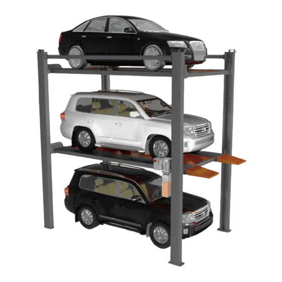
4 POST CAR STACKER
AutoLift AL-2525
Model No: HP-2525 / HP- 2625 Four Post, Three Car Stacker
2500Kg Capacity Lower Platform, 2000Kg Capacity Upper Platform
Design Registration Approval Number: N/A Domestic Application
Design Code: AS1418.9-1996
Note: While all due care and attention has been taken in the preparation of this document, Advance AutoQuip shall not be liable for any inaccuracies or omissions
INSTALLATION MANUAL & OPERATION
INSTRUCTIONS
- READ THE ENTIRE CONTENTS OF THIS MANUAL BEFORE
INSTALLATION AND OPERATION. BY PROCEEDING YOU AGREE THAT
YOU FULLY UNDERSTAND AND COMPREHEND THE FULL CONTENTS
OF THIS MANUAL. FORWARD THIS MANUAL TO ALL OPERATORS.
FAILURE TO OPERATE THIS EQUIPMENT AS DIRECTED MAY CAUSE
Specifications subject to change without notice.
2 McDonald Crescent | Bassendean WA 6054
Ph: 08 9279 1663 | Fax: 08 9279 1667 | E: sales@aaq.net.au | W: www.aaq.net.au
INJURY OR DEATH.
which may occur therein
Advance AutoQuip
READ FIRST
DO NOT use the
machine until you read
and understand all the
dangers, warnings and
cautions in this manual.
Advertisement
Table of Contents

Related Manuals for AAQ AutoLift AL-2525


Summary of Contents for AAQ AutoLift AL-2525
- Page 1 Note: While all due care and attention has been taken in the preparation of this document, Advance AutoQuip shall not be liable for any inaccuracies or omissions which may occur therein Advance AutoQuip 2 McDonald Crescent | Bassendean WA 6054 Ph: 08 9279 1663 | Fax: 08 9279 1667 | E: sales@aaq.net.au | W: www.aaq.net.au...
-
Page 2: Table Of Contents
Safety instructions Product overview Site planning Installation Hydraulic & Electrical Diagrams Operation Surface Cleaning & Protection Maintenance AAQ Australia / Advance AutoQuip Troubleshooting Address: 2 McDonald Crescent Bassendean, WA 6054 Australia Website: www.aaq.net.au Phone: +61 08 9279 1663 Email: sales@aaq.net.au... -
Page 3: Safety Instructions
AL2525 & AL2625 USER MANUAL 1 Safety instructions Please read the en�re contents of this manual prior to installa�on and opera�on. By proceeding you agree that you fully understand and comprehend the full contents of this manual. Forward this manual to all operator. Failure to operate this equipment as directed may cause injury or death. - Page 4 AL2525 & AL2625 USER MANUAL This series contains two models: AL-2525: Each system offers 3 parking spaces, ground and lower pla�orm spaces are for SUVs, capacity 2500kg (5512lbs), upper pla�orm shall be reserved for sedans only whose weight < 2000kg (4400lbs). Required headroom including sedan on top is 6046mm (19.84�).
- Page 5 AL2525 & AL2625 USER MANUAL 2.3. Dimensions 2200 2100 2492 4549 2802 4309 4549 AUTOLIFT 2625 5060 2200 2100 2492 4550 2802 AUTOLIFT 2525 4309 5060 Note: The dimensions may be different as per customer’s special requirement. Please contact our Sales for as-produced dimensions.
-
Page 6: Site Planning
AL2525 & AL2625 USER MANUAL 2.4.Operating conditions Generally, this parking li� must be installed and operated under the following condi�ons: -Voltage supply: 0.9 – 1.1 �mes of nominal supply voltage as s�pulated on sales contract, proforma invoice, or purchase order. -Frequency: 0.99 –... - Page 7 AL2525 & AL2625 USER MANUAL 5399 4199 Ground surface Entrance Direction 4199 5399 (2) Founda�on Diagram 3.2.3 The concrete floor shall be free from any cracks or defects, and should have been dried for at least 28 days. 3.2.4 Pre-embedded anchor bolts are not required. 3.2.5 Keep the working site dry, clean and �dy.
- Page 8 AL2525 & AL2625 USER MANUAL Key switch Power pack Power pack Key switch (3) Loa�ons of Power Pack and Key Switch When you shi� the orienta�on to opposite, the control and other works will be done at the rear side. To do so, please turn the whole structure around, and interchange the ramps and wheel stoppers only.
-
Page 9: Installation
If parts are missing, please contact our local partners or Advance AutoQuip 2000 sales that you originally purchased from. You can also call +61 (08) 9279 1663 or send email to sales@aaq.net.au men�oning the problem that you are experiencing. 4.1 Necessary tools... - Page 10 AL2525 & AL2625 USER MANUAL #1 Main Post Post #2 Post #2 Post #3 (5) Arrangements of four posts (6) Baseplate for power back in the middle of the Main Post...
- Page 11 AL2525 & AL2625 USER MANUAL 4.3.2 Cross beams 4.3.2.1 Lay the front posts (#1 & #2) on ground carefully, and connect the cross beams of both upper and lower pla�orms. (7) Top view of posts and cross beams on ground 4.3.2.2 Crossbeams of upper pla�orm are at the outer side of post, and crossbeams of lower pla�orm are at inner side.
- Page 12 AL2525 & AL2625 USER MANUAL 4.3.3 Erect the posts Erect the 4 posts and locate them precisely according to the chalk lines. And insert 2 diagonal anchor bolts for each li�. Do NOT �ghten at this step. (9) anchor bolts at diagonal 4.3.4 Runways of lower pla�orm Install the runways of lower pla�orm.
- Page 13 AL2525 & AL2625 USER MANUAL 4.3.5 Ramp and wheel stopper of lower pla�orm Mount the ramps and wheel stoppers for lower pla�orm according to the above figure 4.3.4. 4.3.6 Runways of upper pla�orm Install the runways of upper pla�orm. Both runways have edge at inner side to hold cover plates. A clearance of minimum 50mm MUST be kept between upper and lower pla�orms.
- Page 14 AL2525 & AL2625 USER MANUAL Side beams 4.3.8 Connect the front & rear posts with side beams. Do NOT fasten for now. Side beam Side beam (12) Side beams 4.3.9 Top cover plates Preassemble the cover plate and an�-falling lock (triangle-shaped) on ground, and then install the cover plates for each post on top, as well as the U-shaped hooks.
- Page 15 AL2525 & AL2625 USER MANUAL 4.3.10 Steel rope wiring Steel ropes are arranged beneath Le� Runway, and have been pre-wired together with hydraulic cylinder. Find the 4 rope heads and direct them to the direc�on of 4 posts, then pass the ropes into inside of each post through the Bigger Window beneath an�-falling lock holes.
- Page 16 AL2525 & AL2625 USER MANUAL 4.3.11 Inject oil into oil tank The power pack works with #46 hydraulic oil, an�-wearing type, 12 liters. This oil is suitable for normal temperature; for low temperature areas, #32 hydraulic oil is recommended. 4.3.12 Power pack Power pack is mounted on the Base Plate of Main Post.
- Page 17 AL2525 & AL2625 USER MANUAL 4.3.14 Key switch Key switch, also known as control panel, is with key and emergency stop bu�on. Mounted on the main post also, front side. Holes have been reserved in factory. (19) Key switch on front of Main Post 4.3.15 Hydraulic oil lining One piece of oil hose has been connected with cylinder beneath the le�...
- Page 18 AL2525 & AL2625 USER MANUAL 4.3.16 Fasten all the bolts on the structure Fasten all the bolts on the main structure, excluding the anchor bolts. 4.3.17 Limit switch Limit switches (2pcs) are fixed on the main post, one for lower pla�orm and another for upper pla�orm. Installa�on holes have been drilled in factory.
- Page 19 AL2525 & AL2625 USER MANUAL 4.3.18 Wiring of electromagnets All the electromagnets for Upper Pla�orm (4pcs) are installed on post top, together with cover plate. Please do the wiring (W11, W12, W13 & W14) according to the below diagram, all of them are started from W10. Electromagnets for lower pla�orm (4pcs) have been pre-assembled with front &...
- Page 20 AL2525 & AL2625 USER MANUAL (24b) Wiring details 4.3.19 Main power cable Feed power to the electric box, which can be bundled together with Cable W14, and are protected by aluminum cover. Aluminum cover (25) Power cable lining...
- Page 21 AL2525 & AL2625 USER MANUAL 4.3.20 Test run Feed power to the parking system according to electrical diagram in chapter 5.4 Electrical Diagram, and test run for couple of �mes. Re-adjust the levelness of steel ropes and pla�orms if necessary. 4.3.21 Fasten the anchor bolts Once the pla�orms are leveled, fasten all the anchor bolts.
- Page 22 AL2525 & AL2625 USER MANUAL 4.5 Parts drawings 1-2-3-4 Parts Package A Spec. Qty. Item Name M12*35 1-2-3-4 Hexagon Bolt M12*35 Hexagon Bolts...
- Page 23 AL2525 & AL2625 USER MANUAL 1-3-4-C1 3-C1 3-4-C1 Parts Package B Spec. Qty. Item Name M14*45 1-3-4-C1 Hexagon Bolts M14*45 Hexagon Bolts M14*40 Hexagon Bolts Screw Nuts Flat Washer...
- Page 24 AL2525 & AL2625 USER MANUAL Parts Package C Spec. Qty. Item Name Hexagon Bolts M10*35 Cross Recessed Pan Head Bolts M4*25 Cross Recessed Pan Head Bolts M4*12 Hexagon Bolt M8*40 Flat Washer Cross Recessed Pan Head Bolts M5*10 Flat Washer Bolted Anchor Bolts M8*65 Bolted Anchor Bolts...
- Page 25 AL2525 & AL2625 USER MANUAL Parts Package D&E Spec. Qty. Item Name M16*220 Bolted Anchor Bolts...
-
Page 26: Hydraulic & Electrical Diagrams
AL2525 & AL2625 USER MANUAL Hydraulic & Electrical 5 5.1 Hydraulic diagram Filler Cylinder Moter Solenoid valve Gear pump Thro�le valve Relief valve Oil tank One-way valve... - Page 27 Oil tank Cau�on: Serious malfunc�on even human injury may occur if not properly follow adjustment method requested by manufacturer. Contact AAQ or local AAQ partner for permission and technical support before adjustment. 5.2.1 Se�ng pressure adjustment of pressure relief valve Unscrew cap from pressure relief valve, and rotate inner adjus�ng screw to reset pressure.
- Page 28 USER MANUAL HP2525 & HP2625 5.3 Wiring diagram...
- Page 29 AL2525 & AL2625 USER MANUAL 5.4 Electrical diagrams Power supply: 100-240v Single phase Θ U11 N11 100V~240V Power supply: 200v-240v Three phases Θ U1 V1 W1 200V~240V Power supply: 380v-480v Three phases Θ 380V~480V...
-
Page 30: Operation
AL2525 & AL2625 USER MANUAL 6 Operation 6.1 General notes 6.1.1 Only trained persons are allowed to operate the hoist. 6.1.2 Do not operate the hoist if the floor is cracked or any components broken. 6.1.3 Do not operate if there is any person or obstacles above or under pla�orms. 6.1.4 This equipment is designed for car eleva�ng only, drivers are not allowed to ride the hoist or stay in the car. -
Page 31: Surface Cleaning & Protection
AL2525 & AL2625 USER MANUAL 7 Surface Cleaning & Protection 7.1 Surface cleaning 7.1.1 Basic cleaning of the pla�orm A regular cleaning of the pla�orm upper side helps to preserve the system and is absolutely ess¬en�al. ■The pla�orms driven over by cars are swept clean by using a broom or vacuum cleaner. Recommended frequency: Monthly 7.1.2 Cleaning in winter... -
Page 32: Maintenance
AL2525 & AL2625 USER MANUAL 8 Maintenance 8.1 General maintenance Make sure the power is off and no accidental movement before any maintenance work. If the equipment will be not in service for a long �me, the main power supply should be turned off to avoid any accident and to save energy. - Page 33 AL2525 & AL2625 USER MANUAL 8.2.2 Maintenance of power pack ■8.2.2.1 Make sure the power supply is cut off and pla�orm of parking hoist is lowered down to ground before maintenance. ■8.2.2.2 Power line, oil hose or other component is to be replaced with the same specifica�ons. ■8.2.2.3 The whole hydraulic system is to be depressurized completely before opened.
-
Page 34: Troubleshooting
Se�ng pressure of pressure relief valve Turn up se�ng pressure of pressure is too low relief valve (with permission of AAQ). Replace hydraulic oil, clean inlet Hydraulic oil deteriorates or is dirty filter and oil tank Broken gear pump... - Page 35 AL2525 & AL2625 USER MANUAL Valve element of one-way valve is blocked One-way valve to be cleaned or replaced Pressure Valve element of solenoid valve is blocked Solenoid valve to be cleaned or replaced cannot be maintained Fi�ng of outlet pipe is not fastened or Fasten fi�ng of outlet pipe, or replace after platform sealing is broken...
- Page 36 AL2525 & AL2625 USER MANUAL 9.2 Hydraulic cylinder Trouble Possible causes Solutions Aerated oil Air to be eliminate by exhaust Fric�onal resistance is too high or changes due to improper fabrica�on or assembly Reduce fric�onal resistance by lubrica�on of parts with rela�ve mo�on Poor lubrica�on between surfaces of Inlet oil pipe to be replaced moving parts...
- Page 37 Guiding support ring to be repaired or replaced If you con�nue to have issues with your hoist, please contact your dealer or Advance AutoQuip 2000 sales team. Email sales@aaq.net.au, or call us +61 8 9279 1663 Advance AutoQuip 2000 2 McDonald Crescent, Basendean WA 6054 Australia +61 8 9279 1663 sales@aaq.net.au...
- Page 38 THIS WARRANTY SUPERSEDES ALL OTHER WARRANTY POLICIES PREVIOUSLY STATED AND IN ALL OTHER ADVANCE AUTOQUIP’s PRODUCT SPECIFIC LITERATURE. Advance AutoQuip 2 McDonald Crescent | Bassendean WA 6054 Ph: 08 9279 1663 | Fax: 08 9279 1667 | E: sales@aaq.net.au | W: www.aaq.net.au...
- Page 39 SAFETY OPERATING PROCEDURES Vehicle Hoist DO NOT use this machine unless the operator has been thoroughly instructed in its safe use and operation. Safety glasses must be worn at all Long and loose hair must be times in work areas. contained.
- Page 40 COMMISSIONING REPORT 1. Details of Customer Customer Name: Installation Address: 2. Hoist Details Model No: 2 McDonald Crescent Hoist Type: Bassendean WA 6054 Installation Date: P: 08 9279 1663 | E: sales@aaq.net.au 3. Commissioning Report Comments Safety Devices Safety devices incorporated into the design of the vehicle to AS/NZS 1418.9 Welds Visual check all welds completed and comply to requirement of AS/NZS 1554 Hydraulic Equipment and Controls Visual check carried out for leaks Pneumatic Equipment and Controls Visual check carried out for leaks Safety Locks Safety locks tested for correct operation Support Pads Checked for good working order Wheel Stops Supplied with the hoist and in good working order Hoist Motion Limits Checked for correct operation Load Test and Speed Check Hoist checked with load for correct operation and speed control tested Wire Ropes Checked wire ropes for correct installation and tension Concrete Floor Concrete floor is a suitable depth for installation...
- Page 41 COMMISSIONING REPORT Location of Vehicle Hoist & Vehicle Clearances Vehicle hoist or any part of the load is positioned no less than 600mm away from any fixed structure Provisions have been made for effective clearances above the vehicle when the hoist is in its fully raised position. Markings ‐ Hoist Checked for Relevant Marking Including: Make & Model Number Serial number Rated Capacity Reference to maintenance Operation instructions Screw and Nut Gaps Hoist compliance plate showing design registration Functional Test Vehicle hoist has been tested and all safety devices, limit switches and control function interlocks have been tested for correct operation. Demonstration The installer has demonstrated the operation of the vehicle hoist to the owner or operator Electrical Equipment and Controls Lock off isolating switch installed Emergency stop button installed 3. Details of Electrical Contractor Trading Name: EC Licence Number: Address: Telephone Number: 4. Signature Name: ___________________________________________________________ Date: I, being the person responsible for completing the commissioning report have exercised reasonable skill and competency when completing the report and herby certify that the vehicle hoist has been commissioned fit for use as per the Australian / New Zealand Standard 1418.9:1996 Vehicle Hoists.
Need help?
Do you have a question about the AutoLift AL-2525 and is the answer not in the manual?
Questions and answers