Table of Contents
Advertisement
Quick Links
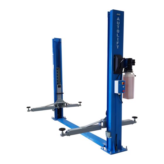
2 POST HOIST
AutoLift AL-9000DD
Symmetric 2 Post Baseplate Vehicle Hoist 4000Kg
Maximum Lifting Capacity
Design Registration Approval Number: WAH21203
Design Code: AS1418.9-1996
Note: While all due care and attention has been taken in the preparation of this document, Advance AutoQuip shall not be liable for any inaccuracies or omissions
Ph: 08 9279 1663 | Fax: 08 9279 1667 | E: sales@aaq.net.au | W: www.aaq.net.au
INSTALLATION MANUAL & OPERATION
INSTRUCTIONS
- READ THE ENTIRE CONTENTS OF THIS MANUAL BEFORE
INSTALLATION AND OPERATION. BY PROCEEDING YOU AGREE THAT
YOU FULLY UNDERSTAND AND COMPREHEND THE FULL CONTENTS
OF THIS MANUAL. FORWARD THIS MANUAL TO ALL OPERATORS.
FAILURE TO OPERATE THIS EQUIPMENT AS DIRECTED MAY CAUSE
Specifications subject to change without notice.
which may occur therein
Advance AutoQuip
2 McDonald Crescent | Bassendean WA 6054
INJURY OR DEATH.
1
READ FIRST
DO NOT use the
machine until you read
and understand all the
dangers, warnings and
cautions in this manual.
Advertisement
Table of Contents

Subscribe to Our Youtube Channel
Related Manuals for AAQ AutoLift AL-900DD


Summary of Contents for AAQ AutoLift AL-900DD
- Page 1 Note: While all due care and attention has been taken in the preparation of this document, Advance AutoQuip shall not be liable for any inaccuracies or omissions which may occur therein Advance AutoQuip 2 McDonald Crescent | Bassendean WA 6054 Ph: 08 9279 1663 | Fax: 08 9279 1667 | E: sales@aaq.net.au | W: www.aaq.net.au...
- Page 2 Printing characters and symbols Throughout this manual, the following symbols and printing characters are used to facilitate reading: Indicates the operations which need proper care Indicates prohibition Indicates a possibility of danger for the operators. Indicates the direction of access for motor vehicles to the lift BOLD TYPE Important information WARNING: Before operating the lift and carrying out any...
-
Page 3: Table Of Contents
Contents Chapter 1 – General information ............................ 4 1.1 Manual keeping ..............................4 1.2 Obligation case of malfunction ......................... 4 1.3 Cautions for the safety of the operator ......................5 1.4 Warnings ................................5 Chapter 2 – Product identification ..........................6 2.1 Warranty certificate ............................ -
Page 4: Chapter 1 - General Information
Chapter 1 – General information This chapter contains warning instructions to operate the lift properly and prevent injury to operators or objects. This manual has been written to be used by shop technicians in charge of the lift (operator) and routine maintenance technician (maintenance operator). -
Page 5: Cautions For The Safety Of The Operator
1.3 Cautions for the safety of the operator Operators must not be under the influence of sedatives, drugs or alcohol when operating the machine. Before operating the lift, operators must be familiar with the position and function of all controls, as well as with the machine features shown in the chapter “Operation and use”... -
Page 6: Chapter 2 - Product Identification
Chapter 2 – Product identification The identification data of the machine are shown in the label placed on the control unit. Use the above data both to order spare parts and when getting in touch with the manufacturer (inquiry). The removal of this label is strictly forbidden. -
Page 7: Chapter 3 - Packing, Transport And Storage
Chapter 3 – Packing, transport and storage Only skilled personnel who are familiar with the lift and this manual shall be allowed to carry out packing, lifting, handling, transport and unpacking operations. 3.1 Transport and package removal ATTENTION: moving and positioning operations can be very dangerous if not performed with the utmost caution. -
Page 8: Chapter 4 - Product Description
Chapter 4 – Product description The lift is composed by two symmetric vertical posts, which must be safely anchored to the ground. The posts are equipped with lifting carriages with electro-hydraulic control system. The lift is operated by an electric motor controlling a hydraulic pump, which delivers the hydraulic fluid to the cylinders at the bottom of the posts for lifting carriages with the sole purpose of performing motor vehicle service, repairing and inspection. -
Page 9: Parts List
4.2 Parts list... -
Page 11: Hydraulic Unit
4.3 Hydraulic unit... -
Page 12: Chapter 5 Technical Specifications
Chapter 5 Technical specifications Model type Z9000DS-D Type TWO POST LIFT WITH BOTTOM BAR Capacity 4000kg <55s Lifting time >20s Descent time Max. lifting height 1850~1925mm Min. lifting height 110mm Overall width 3500mm Overall height 2766mm Drive through 2600mm Power supply 220V50/Hz/1PH, 380V/50HZ/3PH Motor 2.2 KW... -
Page 13: Chapter 6 General Safety Rules
Chapter 6 General safety rules Read this chapter carefully and completely because it contains important information for the safety of the operator and the person in charge of maintenance. 6.1 Safety instruction The messages and pictographs shown are generic in nature and are meant to generally represent hazards common to all automotives lifts regardless of specific style. -
Page 14: Caution
DO NOT STAND UNDER THE VEHICLE ON THE LIFT WHILE LIFT IS OPERATING. DEATH OR SERIOUS INJURY MAY OCCUR. DO NOT LIFT ONE SIDE OF THE VEHICLE POSSIBILITY OF VEHICLE OVERTURN AND/OR DAMAGE TO LIFT MAY HAPPEN DO NOT PLACE ANY POLES UNDER THE VEHICLE AND LOWER IT TO DISMANTLE THE PART FROM THE RAISED VEHICLE 6.3 Caution LIFT TO BE USED BY TRAINED OPERATOR ONLY... - Page 15 ALWAYS USE SAFETY STANDS WHEN REMOVING OR INSTALLING HEAVY COMPONENTS DO NOT HOSE WATER DIRECTLY ON TO LIFT STOP RAISING LIFT WHEN IMBALANCE IS DETECTED. USE VEHICLE MANUFACTURER'S LIFT POINTS USE HEIGHT EXTENDERS WHEN NECESSARY TO ENSURE GOOD CONTACT DO NOT OPERATE LIFT WHEN HYDRAULIC OIL LEAK IS DETECTED AUXILIARY ADAPTERS MAY REDUCE LOAD CAPACITY...
-
Page 16: Chapter 7 Installation
Chapter 7 Installation Only skilled technicians, appointed by the manufacturer, or by authorized dealers, must be allowed to carry out installation. Serious damage to people and to the lift can be caused if installations are made by unskilled personnel. Before carrying out any operations, remember to insert the safety piece of wood between the lower booms and the base frame. -
Page 17: Structure Positioning And Installation
7.4 Structure positioning and installation T o install the lift, set some supports under the post upper ends, remove the pallets and position the posts, one at a time, according to the diagram. Use a lifting system having minimum 500kg capacity. Operations to be executed for mounting and installation: ... -
Page 18: Installation Procedure
7.5 Installation procedure 1. Carriage 2. Shaft 3. 3-stage arm 4. Long hose 5. Side plate of bottom 6. Bottom bar 7. Solenoid power line 8. Balance cable 9. Column 10. Pump hose 11. Protector 12. Motor 13. cable pulley bracket 14. -
Page 19: Hydraulic System Diagram
7.6 Hydraulic system diagram 1. Motor 2. Parachute Valve 3. Unloading valve 4. Descend speed regulating valve 5. Relief valve 6. Gear pump 7. Check valve... -
Page 20: Electric Motor Jumper Pins
7.7 Electric motor jumper pins... -
Page 21: Connection To The Power Sources
7.8 Connection to the power sources Any work on the electrics, however small, must be carried out by qualified personnel only. The lift power supply is AC, 400V, 50Hz unless otherwise required by the user. The power lead must be protected against the over current by means of fuses or by means of a magneto-thermal automatic switch with nominal values as indicated by the chart here below: FEEDING VOLTAGE FUSE NOMINAL VALUE... -
Page 22: Machine Alignment
7.9 Machine alignment 1, Before alignment, to check if the electric circuit and oil hydraulic circuit in good condition, if the lift be installed by correct drawings and if there are some mechanical parts be omitted. 2, To connect the power line to the power source. Open the rotated power switch to 1 position and the power light lights. -
Page 23: Chapter 8 Operation And Use
Chapter 8 Operation and use ATTENTION: Read the instructions in chapter “GENERAL SAFETY RULES” with the utmost attention. ATTENTION: Before operating on the control board, make sure that there are no bystanders and around the lift. 8.1 Control board 1. Main body of control board 2. -
Page 24: Lifting Procedure
8.2Lifting procedure To lift the vehicle, proceed as follows: Check that the lift is in its lowest position Check that the arms are turned in a way not to hamper the vehicle when driving. Turn the arms and pull the extensions in a way that the pads are behind the points foreseen for lifting as indicated by vehicle manufacturer. -
Page 25: Chapter 9 Maintenance
Chapter 9 Maintenance The several maintenance operations to be carried out are described below. A low operation cost and a long life of the machine depends from constant observation of the operations. CAUTION: The listed intervention times are given for information and they refer to normal operating conditions. -
Page 26: Instructions For Adjusting Hydraulic Pressure
9.2 Instructions for adjusting hydraulic pressure Raise lift up to maximum height. Lower lift to rest using down button NOTE: DO NOT REMOVE FINGER FROM DOWN BUTTON FOR AT LEAST 20 SECONDS AFTER LIFT HAS REACHED GROUND LEVEL THIS RELEASES OIL PRESSURE FROM HYDRAULIC HOSES. Remove main hydraulic hose from the fitting. -
Page 27: Chapter 10 Lowering In Emergency Case
Chapter 10 Lowering in emergency case ATTENTION: When performing the “emergency lowering” of the lift, the carriage safety locks must be disengaged first. The following operations shall therefore be performed only when: The lift won’t descend due to electric power cut. ... -
Page 28: Chapter 11 Trouble Shooting
Chapter 11 Trouble shooting A list of possible troubles and solutions is given below TROUBLE POSSIBLE CAUSE SOLUTION The main switch is not turned Turn the switch on There is no power Check Power on to the restore if The lift does not work necessary electrical wires... -
Page 29: Chapter 12 Disposal Of Used Oil
Chapter 12 Disposal of used oil Used oil, which is removed from the power unit and the plant during an oil change, must be treated as a polluting product, in accordance with the legal prescriptions of the country in which the lift is installed. - Page 30 SAFETY OPERATING PROCEDURES Vehicle Hoist DO NOT use this machine unless the operator has been thoroughly instructed in its safe use and operation. Safety glasses must be worn at all Long and loose hair must be times in work areas. contained.
- Page 31 4 TONNE 2 Post Base Plate Lift OPERATING INSTRUCTIONS The lift should only be operated by personnel that have been thoroughly trained in operation and maintenance of the lift. Position the vehicle between the columns, turn off the engine and apply the park brake. Adjust the lifting arms until they reach the supporting position of the vehicle.
- Page 32 THIS WARRANTY SUPERSEDES ALL OTHER WARRANTY POLICIES PREVIOUSLY STATED AND IN ALL OTHER ADVANCE AUTOQUIP’s PRODUCT SPECIFIC LITERATURE. Advance AutoQuip 2 McDonald Crescent | Bassendean WA 6054 Ph: 08 9279 1663 | Fax: 08 9279 1667 | E: sales@aaq.net.au | W: www.aaq.net.au...
- Page 33 COMMISSIONING REPORT 1. Details of Customer Customer Name: Installation Address: 2. Hoist Details Model No: 2 McDonald Crescent Hoist Type: Bassendean WA 6054 Installation Date: P: 08 9279 1663 | E: sales@aaq.net.au 3. Commissioning Report Comments Safety Devices Safety devices incorporated into the design of the vehicle to AS/NZS 1418.9 Welds Visual check all welds completed and comply to requirement of AS/NZS 1554 Hydraulic Equipment and Controls Visual check carried out for leaks Pneumatic Equipment and Controls Visual check carried out for leaks Safety Locks Safety locks tested for correct operation Support Pads Checked for good working order Wheel Stops Supplied with the hoist and in good working order Hoist Motion Limits Checked for correct operation Load Test and Speed Check Hoist checked with load for correct operation and speed control tested Wire Ropes Checked wire ropes for correct installation and tension Concrete Floor Concrete floor is a suitable depth for installation...
- Page 34 COMMISSIONING REPORT Location of Vehicle Hoist & Vehicle Clearances Vehicle hoist or any part of the load is positioned no less than 600mm away from any fixed structure Provisions have been made for effective clearances above the vehicle when the hoist is in its fully raised position. Markings ‐ Hoist Checked for Relevant Marking Including: Make & Model Number Serial number Rated Capacity Reference to maintenance Operation instructions Screw and Nut Gaps Hoist compliance plate showing design registration Functional Test Vehicle hoist has been tested and all safety devices, limit switches and control function interlocks have been tested for correct operation. Demonstration The installer has demonstrated the operation of the vehicle hoist to the owner or operator Electrical Equipment and Controls Lock off isolating switch installed Emergency stop button installed 3. Details of Electrical Contractor Trading Name: EC Licence Number: Address: Telephone Number: 4. Signature Name: ___________________________________________________________ Date: I, being the person responsible for completing the commissioning report have exercised reasonable skill and competency when completing the report and herby certify that the vehicle hoist has been commissioned fit for use as per the Australian / New Zealand Standard 1418.9:1996 Vehicle Hoists.
Need help?
Do you have a question about the AutoLift AL-900DD and is the answer not in the manual?
Questions and answers