Advertisement
Quick Links
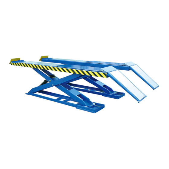
SCISSOR HOIST
AutoLift AL-162016
Full Rise Heavy Duty Scissor Hoist
5500Kg Maximum Lifting Capacity
Note: While all due care and attention has been taken in the preparation of this document, Advance AutoQuip shall not be liable for any inaccuracies or omissions
INSTALLATION MANUAL & OPERATION
INSTRUCTIONS
- READ THE ENTIRE CONTENTS OF THIS MANUAL BEFORE
INSTALLATION AND OPERATION. BY PROCEEDING YOU AGREE THAT
YOU FULLY UNDERSTAND AND COMPREHEND THE FULL CONTENTS
OF THIS MANUAL. FORWARD THIS MANUAL TO ALL OPERATORS.
FAILURE TO OPERATE THIS EQUIPMENT AS DIRECTED MAY CAUSE
Specifications subject to change without notice.
2 McDonald Crescent | Bassendean WA 6054
Ph: 08 9279 1663 | Fax: 08 9279 1667 | E: sales@aaq.net.au | W: www.aaq.net.au
INJURY OR DEATH.
which may occur therein
Advance AutoQuip
READ FIRST
DO NOT use the
machine until you read
and understand all the
dangers, warnings and
cautions in this manual.
Advertisement

Related Manuals for AAQ AutoLift AL-162016


Summary of Contents for AAQ AutoLift AL-162016
- Page 1 Note: While all due care and attention has been taken in the preparation of this document, Advance AutoQuip shall not be liable for any inaccuracies or omissions which may occur therein Advance AutoQuip 2 McDonald Crescent | Bassendean WA 6054 Ph: 08 9279 1663 | Fax: 08 9279 1667 | E: sales@aaq.net.au | W: www.aaq.net.au...
-
Page 2: Table Of Contents
162016 CONTENTS Packing, transport and storage………………………………………………… introduction……………………………………………………………………… Chapter 1 Description of the machine………………………………………… Chapter 2 Technical specifications……………………………………………… Chapter 3 Safety………………………………………………………………… Chapter 4 Installation…………………………………………………………… Chapter 5 Adjusting……………………………………………………………… Chapter 6 Operating principles and use………………………………………… Chapter 7 Maintenance ………………………………………………………… Chapter 8 Troubleshooting……………………………………………………… Chapter 9 Appendix ………………………………………………………………... -
Page 3: Packing, Transport And Storage
162016 PACKING, TRANSPORT AND STORAGE All packing, lifting, handling, transport and unpacking operations are to be performed exclusively by expert personnel PACKING AND TRANSPORT Packing :(Picture 1) Standard equipment: oil line and accessory(1#BOX), main and sub beam(3#、 4#BOX), control box(2#BOX), font and back stop board(5#BOX), standard equipment, total is 5 pieces. - Page 4 162016 PACKING, TRANSPORT AND STORAGE Transport:(picture 2) Packing can be lifted or moved by lift trucks, cranes or bridge cranes. In case of slinging, a second person must always take care of the load, in order to avoid dangerous oscillations. At the arrival of the goods, check for possible damage due to transport operations.
- Page 5 162016 INTRODUCTION This manual has been prepared for workshop personnel expert in the use of the lift (operator) and technicians responsible for routine maintenance ( maintenance fitter); read the manual before carrying out any operation with the lift and/or the packing. This manual contains important information regarding: the personal safety of operators and maintenance workers.
-
Page 6: Chapter 1 Description Of The Machine
162016 NOTE: Manufacturer own the right to make little change for the manual Chapter 1 DESCRIPTION OF THE MACHINE MACHINE The scissor lifts suitable for use in four wheel alignment, vehicle tests, maintenance and care for various types of small automobiles. Features: -imported electric components. -
Page 7: Chapter 2 Technical Specifications
162016 a makeshift press for crushing purposes, use as good lift. And not lift the vehicle which weight exceed the maximum weight. Chapter 2 TECHNICAL SPECIFICATIONS SPECIFICATIONS Capacity 3.5t 4.0t 5.5t Drive Electrical hydraulic Max lift weight 3500kg 4000kg 5000kg Sub machine lift weight 2000kg 2000kg... - Page 8 162016 Chapter 2 TECHNICAL SPECIFICATIONS 3.5t (4.0t) (5.5t) (picture 3) MOTOR PUMP: PUMP: Type------------------------------Y90L Type--------------------------------- P4.3 Power---------------------------2.2Kw Model------------------------ teeth pump Voltage-------------AC400V or 230V Dispacement---------------------- 4.3cc/r Ie-------------------------------400V:5A Transmission: joint type-------230V:8.7A Frequency-------------------------50Hz Relief valve Poles-------------------------------4 Continuous working pressure-- 210bar Speed---------------------1450rpm/min Intermittent working pressure-150-300 bar Building shape---------------------B14 Isulation class----------- -------------F When connecting the motor refer to...
- Page 9 162016 Installation scheme for lift To install the lift it is necessary to execute suitable foundations with the following characteristics: -concrete type 425 -thickness of concrete≥150mm, the leveling of whole length≤10mm -perfect parallelism between holes. <3.5t> 4.0t(5.5t) (picture 4) The thickness and levelling of the base concrete are essential and the levelling adjustment ability of the machine itself cannot be relied upon to excessively.
- Page 10 162016 Chapter 2 TECHNICAL SPECIFICATIONS Types of vechles suitable for being lifted and overall dimensions Lift are suitable for virtually all vehicles with total weight of no more than 3500 kg or 4000kg or 5500kg and with dimensions not exceeding the below data. The following diagrams illustrate criteria used to define the operating limits of the lift.
-
Page 11: Chapter 3 Safety
162016 Chapter 3 SAFETY Read this chapter carefully and completely since important information for the safety of the operator or others in case of improper use of the lift is included. In the following text there are clear explanations regarding certain situations of risk or danger that may arise during the operation or maintenance of the lift, the safety device installed and the correct use of such systems, residual risks and operative procedures to use (general specific precautions to... - Page 12 162016 ( picture 6) Chapter 3 SAFETY GENERAL PRECAUTIONS The operator and the maintenance fitter are required to observe the prescriptions of safety regulation in force in the country of installation of the lift. Furthermore, the operator and maintenance fitter must: -always work in the stations specified and illustrated in this manual;...
- Page 13 162016 maximum height, and projection (vehicle length and width); -make sure that there are no person on the platforms during up and down movements and during standing. (picture 7) Chapter 3 SAFETY (picture 8) RISKS FOR PERSONNEL This heading illustrates potential risks for the operator, maintenance fitter, or any other person present in the area around the lift, result from incorrect use of the lift.
- Page 14 162016 from entering the area beneath the movable parts of the lift. The lift operator must not start the manoeuvre unit it has been clearly established that there are no person in potentially dangerous positions. RISK OF IMPACT Caused by the parts of the lift or the vehicle that are positioned at head height.
- Page 15 162016 (picture 11) RISK OF VEHICLE FALLING FROM LIFT This hazard may arise in the case of incorrect positioning of the vehicle on the platforms, incorrect stopping of the vehicle, or in the case of vehicles of dimensions that are not compatible with the capacity of the lift. (picture 12) Never attempt to perform tests by driving the vehicle while it is on the platforms...
- Page 16 162016 (picture 13) RISK OF ELECTRIC SHODK Risk of electric shock in areas of the lift housing electrical wiring. Do not use jets of water, steam solvents or paint next to the lift, and take special care to keep such substances clear of the electrical control panel. RISKS RELATED TO IMAPPROPRIATE LIGHTING The operator and the maintenance fitter must be able to assure that all the areas of the lift are properly and uniformly illuminate compliance with the...
-
Page 17: Chapter 4 Installation
162016 emergency is also necessary, the room must be previously arranged for the power supply and pneumatic feed of the car lift. The room must be 4000 mm in height, at least, the car lift can be placed on any floor, as long as it is perfectly level and sufficiently resistant. - Page 18 162016 (picture ROLLING JACK INSTALLATION -adjust the distance of the rolling jack, put the rolling jack between the slide track. -adjust the sub beam to make sure the sliding of the rolling jack. LINE CONNECTION Connect the electrical and oil line according to the electric wiring diagram and oil line connection To avoid the unexpected lift closure due to mechanical safety device release insert wooden pieces in the inner part of the base frame.
- Page 19 162016 (picture 16) (picture 17) The limit switch connection (equipped with electrical carriage) Connect the PE,10# from the control box with metal hoses to the limit switch of electrical rolling jack. Connect the hydraulic hoses as oil route connection drawing. Electrical carriage oil line connection: The oil line of electrical carriage from manual selector to oil tank .
- Page 20 162016 (picture 19 (picture 20) Main machine oil make-up adjustment 1-close the oil make up stop valve “H” on the main machine and open the oil make up stop valve “G” on the main machine. 2-press “lift” button SB1, and thus the left platform ( looking from machine head direction ) is lifted to about 1000mm.
- Page 21 162016 right, -fix the anchor bolts (16 bolts) with a percussion electric drill ( percussion drill bit is of 16, drill to 120mm hole and clean the hole. (picture21) Level adjustment. -By using a level bar and the horizontal pipe and adjusting the adjustment screws at tow sides of the base plate.
- Page 22 162016 the slide resistant triangle woods should be used. -pay attention to the synchronization of the lifting and lowering. If any abnormal is found, stop the machine timely, check and remove the trouble. -when locking the main machine, the two platforms should be kept at the same height.
- Page 23 162016 -open the oil make up stop valve “H” on the main machine and close the oil make up stop valve “G” on the main machine. -press “up” button SB1, two platforms of the main machine are lifted to the same height .
-
Page 24: Chapter 8 Troubleshooting
162016 Chapter 7 TROUBLESHOOTING Cause and Phenomena Resolutions The motor does not run Connection power Check and correct wire connection. ① in lifting operation. supply wires or zero wire is not correct. ② The AC contactor in the If the motor operates when forcing the contactor circuit of the motor does down with an isolation rod, check the control circuit. -
Page 25: Chapter 9 Appendix
162016 Chapter 8 APPENDIX... - Page 26 162016 Chapter 9 APPENDIX...
- Page 27 5500kg Scissor Hoist OPERATING INSTRUCTIONS The hoist should only be operated by personnel that have been thoroughly trained in operation and maintenance of the hoist. Drive the vehicle evenly over the scissor platform and apply the park brake. Install the four rubber lifting blocks to the underside of the jacking points of the hoist.
- Page 28 SAFETY OPERATING PROCEDURES Vehicle Hoist DO NOT use this machine unless the operator has been thoroughly instructed in its safe use and operation. Safety glasses must be worn at all Long and loose hair must be times in work areas. contained.
- Page 29 THIS WARRANTY SUPERSEDES ALL OTHER WARRANTY POLICIES PREVIOUSLY STATED AND IN ALL OTHER ADVANCE AUTOQUIP’s PRODUCT SPECIFIC LITERATURE. Advance AutoQuip 2 McDonald Crescent | Bassendean WA 6054 Ph: 08 9279 1663 | Fax: 08 9279 1667 | E: sales@aaq.net.au | W: www.aaq.net.au...
- Page 30 COMMISSIONING REPORT 1. Details of Customer Customer Name: Installation Address: 2. Hoist Details Model No: 2 McDonald Crescent Hoist Type: Bassendean WA 6054 Installation Date: P: 08 9279 1663 | E: sales@aaq.net.au 3. Commissioning Report Comments Safety Devices Safety devices incorporated into the design of the vehicle to AS/NZS 1418.9 Welds Visual check all welds completed and comply to requirement of AS/NZS 1554 Hydraulic Equipment and Controls Visual check carried out for leaks Pneumatic Equipment and Controls Visual check carried out for leaks Safety Locks Safety locks tested for correct operation Support Pads Checked for good working order Wheel Stops Supplied with the hoist and in good working order Hoist Motion Limits Checked for correct operation Load Test and Speed Check Hoist checked with load for correct operation and speed control tested Wire Ropes Checked wire ropes for correct installation and tension Concrete Floor Concrete floor is a suitable depth for installation...
- Page 31 COMMISSIONING REPORT Location of Vehicle Hoist & Vehicle Clearances Vehicle hoist or any part of the load is positioned no less than 600mm away from any fixed structure Provisions have been made for effective clearances above the vehicle when the hoist is in its fully raised position. Markings ‐ Hoist Checked for Relevant Marking Including: Make & Model Number Serial number Rated Capacity Reference to maintenance Operation instructions Screw and Nut Gaps Hoist compliance plate showing design registration Functional Test Vehicle hoist has been tested and all safety devices, limit switches and control function interlocks have been tested for correct operation. Demonstration The installer has demonstrated the operation of the vehicle hoist to the owner or operator Electrical Equipment and Controls Lock off isolating switch installed Emergency stop button installed 3. Details of Electrical Contractor Trading Name: EC Licence Number: Address: Telephone Number: 4. Signature Name: ___________________________________________________________ Date: I, being the person responsible for completing the commissioning report have exercised reasonable skill and competency when completing the report and herby certify that the vehicle hoist has been commissioned fit for use as per the Australian / New Zealand Standard 1418.9:1996 Vehicle Hoists.
Need help?
Do you have a question about the AutoLift AL-162016 and is the answer not in the manual?
Questions and answers