Table of Contents
Advertisement
Quick Links
SCISSOR HOIST
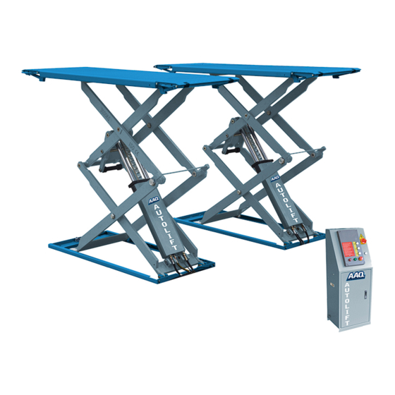
AutoLift AL-3000AG
Model No: FT-8801 Full Rise Heavy Duty Scissor Hoist
3000Kg Maximum Lifting Capacity
Design Registration Approval Number: WAH21610
Design Code: AS1418.9-1996
Note: While all due care and attention has been taken in the preparation of this document, Advance AutoQuip shall not be liable for any inaccuracies or omissions
INSTALLATION MANUAL & OPERATION
INSTRUCTIONS
- READ THE ENTIRE CONTENTS OF THIS MANUAL BEFORE
INSTALLATION AND OPERATION. BY PROCEEDING YOU AGREE THAT
YOU FULLY UNDERSTAND AND COMPREHEND THE FULL CONTENTS
OF THIS MANUAL. FORWARD THIS MANUAL TO ALL OPERATORS.
FAILURE TO OPERATE THIS EQUIPMENT AS DIRECTED MAY CAUSE
Specifications subject to change without notice.
2 McDonald Crescent | Bassendean WA 6054
Ph: 08 9279 1663 | Fax: 08 9279 1667 | E: sales@aaq.net.au | W: www.aaq.net.au
INJURY OR DEATH.
which may occur therein
Advance AutoQuip
READ FIRST
DO NOT use the
machine until you read
and understand all the
dangers, warnings and
cautions in this manual.
Advertisement
Table of Contents

Related Manuals for AAQ AutoLift AL-3000AG


Summary of Contents for AAQ AutoLift AL-3000AG
- Page 1 Note: While all due care and attention has been taken in the preparation of this document, Advance AutoQuip shall not be liable for any inaccuracies or omissions which may occur therein Advance AutoQuip 2 McDonald Crescent | Bassendean WA 6054 Ph: 08 9279 1663 | Fax: 08 9279 1667 | E: sales@aaq.net.au | W: www.aaq.net.au...
- Page 2 Installation, Operation and Parts Manual AL-3000AG (FL-8801) INDEX 1. Important safety instructions…………………………………………………………………………………..….2~4 1.1 Important notices 1.2 Qualified personnel 1.3 Danger notices 1.4 Training 1.5Warning signs 2. Overview of the hoist………………………………………………….………….……………………………………..5 2.1 General descriptions 2.2 Technical data 2.3 Construction of the hoist 3.
-
Page 3: Important Safety Instructions
Installation, Operation and Parts Manual AL-3000AG (FL-8801) IMPORTANT SAFETY INSTRUCTIONS 1.1 Important notices EverLift will offer one-year's quality warranty for the whole machine,during which any quality problem will be properly solved to the user's satisfaction. However, we will not take any responsibility for whatever bad consequence resulted from improper installation and operation, overload running or unqualified ground condition. -
Page 4: Warning Signs
Installation, Operation and Parts Manual AL-3000AG (FL-8801) 1.3.9 Always insure the safety latches are engaged before any attempt to work near or under the vehicle. Never remove safety related components from the hoist. Do not use if safety related components are damaged or missing. 1.3.10 Do not rock the vehicle while on the hoist or remove any heavy component from vehicle that may cause excessive weight shift. -
Page 5: General Descriptions
Installation, Operation and Parts Manual AL-3000AG (FL-8801) OVERVIEW OF THE HOIST 2.1 General descriptions This full rise scissor hoist is of pretty lower profile when at its lowest position. Its four cylinder structure makes the lowest 110mm clearance from ground come true. Currently this model is designed with two different leveling systems-auto leveling and manual leveling. -
Page 6: Installation Instructions
Installation, Operation and Parts Manual AL-3000AG (FL-8801) INSTALLATION INSTRUCTIONS 3.1 Preparations before installation 3.1.1 Tools and equipments needed √ Electrical drill √ Open wrenches √ Screw drivers √Adjustable spanner 3.1.2 List for parts checking ---Annex 1(Packing list) Unfold the package and check if any parts missed as per Annex 1. Do not hesitate to contact us in case any parts missed, but if you do not contact us and insist installing upon the lack of some parts, EverLift as well as our dealers will not bear any responsibility for this and will charge for any parts subsequently demanded by the buyer. - Page 7 Installation, Operation and Parts Manual AL-3000AG (FL-8801) Step2: Connect oil hose (This step is extremely important, so do refer to the diagram for of oil hose connection and understand the following instructions before proceeding) 1. make sure there is nothing obstructed or dirty left in the hose. 2.
- Page 8 Installation, Operation and Parts Manual AL-3000AG (FL-8801) Step3: Connect the wiring and air system Connect exterior wires as per the wiring diagram, with the black for phase wire, the blue for null wire, and the green -yellow for grounded conductor. Connect the compressed air supply to the air inlet of the air pump and then have the air hose (Ф10×Ф7mm, prepared by the user) of the pneumatic safety lock connected to the air outlet of the pump.
- Page 9 Installation, Operation and Parts Manual AL-3000AG (FL-8801) Air hose Step4: Fill with hydraulic oil Pour into the oil tank with 16liters of anti-grinding oil. Level of the oil shall be 10mm to 40mm away from the top of the tank. (Users can measure it by the feeler attached on the lid)
- Page 10 Installation, Operation and Parts Manual AL-3000AG (FL-8801) Step5: Leveling Attention: Level the platforms before connecting height limit switch because if not, platforms can not rise to the highest position. Before leveling, make sure the oil hoses are correctly connected. Otherwise, oil cylinders may not work synchronously or could be damaged.
- Page 11 Installation, Operation and Parts Manual AL-3000AG (FL-8801) One valve open, the other closed: leveling condition A.1. Open both leveling valves and press the UP button to have both platforms raised to the highest positions. Repeat this step for two or three times.
- Page 12 Installation, Operation and Parts Manual AL-3000AG (FL-8801) Step8: Install oil hose protectors. 3.4 Items to be checked after installation. Check items Are two platforms adjusted with the same level? Are oil hose tightly connected? Are all electric connections correct? Are valves of the pump unit oil tight? OPERATION INSTRUCTIONS 4.1 Precautions Check all the joints of oil hose.
- Page 13 Installation, Operation and Parts Manual AL-3000AG (FL-8801) 4.2 Descriptions of control box 4.3 Flow chart for operation Lowering Raising Turn on the power switch Press UP button...
-
Page 14: Emergency Lowering In Case Of No Power
Installation, Operation and Parts Manual AL-3000AG (FL-8801) 4.4 Operation instructions Raise the hoist 1. Make sure that you have read and understood the operation manual before operation. 2. Drive and park the vehicle midway between two platforms. 3. Place the four rubber pads under the prop-points of the vehicle and ensure car’s gravity have fallen on the rubber pads. 4. - Page 15 Installation, Operation and Parts Manual AL-3000AG (FL-8801) 2. Screw loose the core of the solenoid unloading valve fixed on the hydraulic block. Pneumatic safety lock is engaged. 1. Take down the removable plug from the hydraulic block. 2. Connect the optional hand pump to hydraulic block at the point where the removable plug used to be fitted. 3.
- Page 16 Installation, Operation and Parts Manual AL-3000AG (FL-8801) 4. Screw loose the core of solenoid unloading valve fixed on the hydraulic block.
-
Page 17: Troubleshooting
Installation, Operation and Parts Manual AL-3000AG (FL-8801) TROUBLE SHOOTING ATTENTION: If the trouble could not be fixed by yourself, please do not hesitate to contact us for help .We will offer our service at the earliest time we can. By the way, your troubles will be judged and solved much faster if you could provide us more details or pictures of the trouble. -
Page 18: Maintenance
Installation, Operation and Parts Manual AL-3000AG (FL-8801) MAINTENANCE Easy and low cost routine maintenance can ensure the hoist work normally and safely. Following are requirements for routine maintenance. You may choose the frequency of routine maintenance by consulting your lift’s working conditions and time. The following parts need to be lubricated. - Page 19 Installation, Operation and Parts Manual AL-3000AG (FL-8801) ANNEX Annex 1, Packing List of the whole hoist Name Drawing#/Size Material# Description Note Low-profile scissor hoist FL-8801 Assembly A pack Proection cover A FL-8801-A9 Q235A Name Drawing#/Size Material# Description Note Proection cover B FL-8801-A10 Q235A Proection cover C...
- Page 20 Installation, Operation and Parts Manual AL-3000AG (FL-8801) Annex 3, Hydraulic working system 1 .Emergent unloading valve 2. Electrical unloading valve 3. One-way valve 4. Overflow valve 5. Lowering throttle valve 6. Oil supplementing ball valve 7. Oil supplementing ball valve 8.
- Page 21 Installation, Operation and Parts Manual AL-3000AG (FL-8801) Annex4, Wiring diagram Single phase...
-
Page 22: Three Phase
Installation, Operation and Parts Manual AL-3000AG (FL-8801) Three phase... - Page 23 Installation, Operation and Parts Manual AL-3000AG (FL-8801)
- Page 24 Installation, Operation and Parts Manual AL-3000AG (FL-8801)
- Page 25 Installation, Operation and Parts Manual AL-3000AG (FL-8801)
- Page 26 Installation, Operation and Parts Manual AL-3000AG (FL-8801) Annex5, Diagram for air supply connection Annex 6, Separated drawings for the hoist For the pump: DESCRIPTION Motor Hydraulic block Overflow valve Fitting Cushion valve Absorbing oil hose Oil filter Throttle valve Oil hose tie-in Electrical unloading valve One-way valve Gear pump...
- Page 27 Installation, Operation and Parts Manual AL-3000AG (FL-8801) For mechanical assembly...
- Page 28 Installation, Operation and Parts Manual AL-3000AG (FL-8801) Material# Name Drawing# Property Note Base plate A FL-8801-A1-B1 Welded Circlip 25 GB/T894.1-1986 Standard Rotor shaft FL-8801-A1-B5 Movable arm C FL-8801-A2-B3 Welded Hex head cone screw M6*10 GB/T78-2000 Standard Total qty Cross sunken head screw M8*16 GB/T819.1-1986 Standard Total qty...
- Page 29 Installation, Operation and Parts Manual AL-3000AG (FL-8801) Material# Name Drawing# Property Note Inside hex cap screw M8*12 GB/T78-2000 Standard Same as item 5 Thin spacer FL-8801-A2-B8 Q235A Rotor shaft FL-8801-A3-B6 Welded Bearing 3025 SF-1 Standard Oil nozzle M8*1 JB/T7940.1-1985 Standard Same as item 11 Start wheel FL-8801-A3-B4...
- Page 30 Installation, Operation and Parts Manual AL-3000AG (FL-8801) Material# Name Drawing# Property Note Oil hose FL-8801-A4-B10 Assembly 4.1m Three-way connector FL-8801-A4-B7 Oil hose FL-8801-A4-B10 Assembly 0.25m Oil hose Assembly 0.23m Oil hose FL-8801-A4-B10 Assembly 1.65m Protection cover plate A FL-8801-A17 Q235A Protection cover plate B FL-8801-A10 Q235A...
- Page 31 Installation, Operation and Parts Manual AL-3000AG (FL-8801) Material # Name Spec. Unit Qty/set Pictures Circuit breaker DZ47-63 C16 /3P Circuit breaker DZ47-63 C32 /2P Circuit breaker DZ47-63 C3 /1P Pneumatic valve 3V210-08/DC24 Limit switch ME8104 Bridge rectifier KBPC5A-35A Capacitor 4700UF/50V Control box Bigger Relay...
- Page 32 Installation, Operation and Parts Manual AL-3000AG (FL-8801) Spare parts list---mechanical part Material# Name Drawing# Qty/set Description Note Straight oil cup M8*1 JB/T7940.1-1985 Standard Pad block FL-8801-A2-B17 Nylon Positioning slider FL-8801-A2-B13 Nylon 1010 Safety block connection FL-8801-A4-B5 Q235A Air cylinder AA6*10 Assembly Fixing plate for air cylinder FL-8801-A4-B6...
- Page 33 3000kg Scissor Hoist OPERATING INSTRUCTIONS The hoist should only be operated by personnel that have been thoroughly trained in operation and maintenance of the hoist. Drive the vehicle evenly over the scissor platform and apply the park brake. Install the four rubber lifting blocks to the underside of the jacking points of the hoist.
- Page 34 SAFETY OPERATING PROCEDURES Vehicle Hoist DO NOT use this machine unless the operator has been thoroughly instructed in its safe use and operation. Safety glasses must be worn at all Long and loose hair must be times in work areas. contained.
- Page 35 THIS WARRANTY SUPERSEDES ALL OTHER WARRANTY POLICIES PREVIOUSLY STATED AND IN ALL OTHER ADVANCE AUTOQUIP’s PRODUCT SPECIFIC LITERATURE. Advance AutoQuip 2 McDonald Crescent | Bassendean WA 6054 Ph: 08 9279 1663 | Fax: 08 9279 1667 | E: sales@aaq.net.au | W: www.aaq.net.au...
- Page 36 COMMISSIONING REPORT 1. Details of Customer Customer Name: Installation Address: 2. Hoist Details Model No: 2 McDonald Crescent Hoist Type: Bassendean WA 6054 Installation Date: P: 08 9279 1663 | E: sales@aaq.net.au 3. Commissioning Report Comments Safety Devices Safety devices incorporated into the design of the vehicle to AS/NZS 1418.9 Welds Visual check all welds completed and comply to requirement of AS/NZS 1554 Hydraulic Equipment and Controls Visual check carried out for leaks Pneumatic Equipment and Controls Visual check carried out for leaks Safety Locks Safety locks tested for correct operation Support Pads Checked for good working order Wheel Stops Supplied with the hoist and in good working order Hoist Motion Limits Checked for correct operation Load Test and Speed Check Hoist checked with load for correct operation and speed control tested Wire Ropes Checked wire ropes for correct installation and tension Concrete Floor Concrete floor is a suitable depth for installation...
- Page 37 COMMISSIONING REPORT Location of Vehicle Hoist & Vehicle Clearances Vehicle hoist or any part of the load is positioned no less than 600mm away from any fixed structure Provisions have been made for effective clearances above the vehicle when the hoist is in its fully raised position. Markings ‐ Hoist Checked for Relevant Marking Including: Make & Model Number Serial number Rated Capacity Reference to maintenance Operation instructions Screw and Nut Gaps Hoist compliance plate showing design registration Functional Test Vehicle hoist has been tested and all safety devices, limit switches and control function interlocks have been tested for correct operation. Demonstration The installer has demonstrated the operation of the vehicle hoist to the owner or operator Electrical Equipment and Controls Lock off isolating switch installed Emergency stop button installed 3. Details of Electrical Contractor Trading Name: EC Licence Number: Address: Telephone Number: 4. Signature Name: ___________________________________________________________ Date: I, being the person responsible for completing the commissioning report have exercised reasonable skill and competency when completing the report and herby certify that the vehicle hoist has been commissioned fit for use as per the Australian / New Zealand Standard 1418.9:1996 Vehicle Hoists.
Need help?
Do you have a question about the AutoLift AL-3000AG and is the answer not in the manual?
Questions and answers