Table of Contents
Advertisement
Quick Links
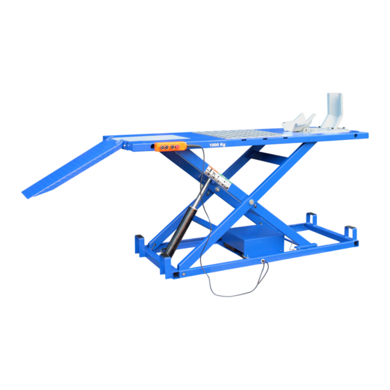
MOTORCYCLE HOIST
AutoLift AL-243156
Extra Heavy Duty Electric Operated Motorcycle Hoist
1000Kg Maximum Lifting Capacity
Design Code: AS1418.9-1996
Note: While all due care and attention has been taken in the preparation of this document, Advance AutoQuip shall not be liable for any inaccuracies or omissions
Ph: 08 9279 1663 | Fax: 08 9279 1667 | E: sales@aaq.net.au | W: www.aaq.net.au
INSTALLATION MANUAL & OPERATION
INSTRUCTIONS
- READ THE ENTIRE CONTENTS OF THIS MANUAL BEFORE
INSTALLATION AND OPERATION. BY PROCEEDING YOU AGREE THAT
YOU FULLY UNDERSTAND AND COMPREHEND THE FULL CONTENTS
OF THIS MANUAL. FORWARD THIS MANUAL TO ALL OPERATORS.
FAILURE TO OPERATE THIS EQUIPMENT AS DIRECTED MAY CAUSE
Specifications subject to change without notice.
which may occur therein
Advance AutoQuip
2 McDonald Crescent | Bassendean WA 6054
INJURY OR DEATH.
READ FIRST
DO NOT use the
machine until you read
and understand all the
dangers, warnings and
cautions in this manual.
Advertisement
Table of Contents

Related Manuals for AAQ AutoLift AL-243156


Summary of Contents for AAQ AutoLift AL-243156
- Page 1 Note: While all due care and attention has been taken in the preparation of this document, Advance AutoQuip shall not be liable for any inaccuracies or omissions which may occur therein Advance AutoQuip 2 McDonald Crescent | Bassendean WA 6054 Ph: 08 9279 1663 | Fax: 08 9279 1667 | E: sales@aaq.net.au | W: www.aaq.net.au...
-
Page 2: Table Of Contents
CONTENT Safety 1.1 Note, Caution and Warning 1.2 Important Information 1.3 Safety Instructions Technical Manual 2.1 Product Description 2.2 Technical Data 2.3 Hydraulic Scheme 2.4 Circuit Diagram Preparing and installation 3.1 Site Selection 3.2 Surface Condition 3.3 Installation Instruction 3.4 Preparation for Starting up Operation 4.1 Caution and Warning Label 4.2 Operation Instructions... -
Page 3: Safety
1. Safety Information 1.1 Note, Caution and Warning This document uses the following conventions—Note, Caution and Warning – to alert you to special instructions, tips, or hazards for a given procedure. Please familiarize yourself with the conventions described below. Indicates important information that requires special attention, such as a procedure for a specific vehicle, or tips on operating the equipment. -
Page 4: Safety Instructions
1.3 Safety Instructions 1. Do not raise a vehicle on the hoist until the initialization is completed as described in this manual. 2. Technicians should be trained to use and care for the hoist by familiarizing themselves with the publications listed above. The hoist should never be operated by an untrained person. - Page 5 16. Use the hoist only as described in this manual, use only manufacturer’s recommended attachments. 17. Unusual vehicles, such as limousines, RV’s, and long wheelbase vehicles, may not be suitable for lifting on this equipment. If necessary, consult with the manufacturer or the manufacturer’s representative.
- Page 6 ‐ ‐ ...
-
Page 7: Product Description
2. Technical Specifiaction 2.1 Product Description The 243156 motorcycle & ATV hoist is used for repairing and maintaining motorcycles by AC power source incorporating the latest safety technologies. Its plug connector accords with European standard and VDE rated. Designed and manufactured for a lifting capacity of 1,000kg, is fully capable for lifting motorcycles, ATVs and safely holding them in an elevated position. - Page 8 562 mm 785 mm 2250 mm Fig. 1 ‐ ‐ ...
-
Page 9: Hydraulic Scheme
Hydraulic c Scheme Oil tank Mesh 3. G Gear pump 4. M Motor One-way va Mesh 7. S Solenoid valv 8. R Restrictor va Relief valve Restrictor va alve 11. C Cylinder 12. P Pipe Fig. 2 ‐ ‐ ... -
Page 10: Circuit Diagram
2.4 Circuit Diagram Item Name Type and Specifications Qty. switch LA42P 220V 10A switch LA42P 220V 10A switch LA42P 220V 10A switch LA42MY 220V 10A AC contactor NC1-09/10-24VAC 400V Overload relay TA25DU transformer ABL6TS06B bridge rectifier KBPC1010 1A 1000V Fuse ∮5×20 delay Fuse ∮5×20 delay 3.15A... -
Page 11: Preparing And Installation
3. Preparing and installation 3.1. Site Selection The hydraulic motorcycle hoist is designed only for indoor use. Application in a room with explosion hazard is not permitted. Setting in a wet place, a car wash center for instance, is forbidden. 3.2. - Page 12 Insert wheel vice base into the rails and make certain there is clearance to allow a smooth sliding motion ( Fig. 6). Bolt the rails to the deck. Then mount on the wheel vice.(Fig. 7). Insert the sideboard bar into the side holes. Bolt them with bolts. ( Fig.8,9,10) Put on the side board and the rear ramps.
-
Page 13: Operation
4. Operation Be sure to read and familiarize yourself with the Safety Instructions at the beginning of this manual. Be sure to wear gloves, protection glasses and all necessary personal protective equipments. Failure to follow Safety Instructions may result in property damage, personal injury or death. - Page 14 Push the equipment over the hoist while keeping the equipment parallel with the hoist and aligning the center of gravity of the equipment with the center of the hoist. For motorcycles and other two wheel vehicles/equipment, push forward until the front wheel goes into the wheel clamps. Motorcycle Fixing.
- Page 15 ) on controller to lower down the hoist to the required c. Then press DOWN button ( working height or to its lowest (fully collapsed) position. d. Observe the complete lowering process for any unexpected movement. e. Push back the vehicle out of the hoist if the hoist is in the lowest position. Remove any tools or stands from under vehicle before moving vehicle Remain clear of hoist when lowering vehicle.
- Page 16 4.27 To lower the wheel clamp with wheel If the motorcycle wheel need to be taken off, first loose the nuts on the wheel shaft and rest the wheel on the clamp. Loose the bolts on the platform end of the wheel board. Then move them aside with hand hold the wheel clamp base.
-
Page 17: Maintenance Instructions
5. Maintenance Instructions Contact your service provider for instruction before starting up if you are not completely familiar with automotive hoist maintenance procedures. Only qualified personnel can perform maintenance on this equipment. Any failure in operation may cause personal injury or death. - Page 18 Every 6 Months Check the hydraulic oil if it is enough. Ensure the liquid level of the hydraulic oil that under the max graduation and above the min graduation. The tank capacity of the power unit is about 3L, Refill with hydraulic oil if necessary: AW 32 or 46 Non-Detergent Non-Foaming Anti-Wear Hydraulic Oil.
-
Page 19: Parts Drawing And Parts Code List
Parts Drawing and Parts Code List 6.1 Parts drawing-A1 ‐ ‐ ... - Page 20 6.2 Parts drawing-A2 48 47 ‐ ‐ ...
- Page 21 6.3 Parts drawing-A3 54-4 ‐ ‐ ...
- Page 22 6.4 Parts drawing-A4 54-8 54-7 54-9 54-10 54-6 54-5 54-11 54-12 54-13 54-4 54-14 54-3 54-2 54-1 ‐ ‐ ...
- Page 23 6.5 Parts drawing-A5 ‐ ‐ ...
- Page 24 6.6 Parts drawing-A6 40-10 40-6 40-12 40-11 40-14 40-4 40-13 40-15 40-16 40-9 40-17 40-8 40-7 40-6 40-5 40-4 40-3 40-2 40-1 44-2 44-1 ‐ ‐ ...
- Page 25 6.7 Parts code list -A ITEM CODE DESCRIPTION JP24-00015-000 side ramp JP24-00014-000 middle ramp 5117-10020-000 screw JP24-00019-000 fixing plate 1# JP24-00027-000 fixing plate 2# JP24-00022-000 connecting rod JP04-00005-000 JP24-00008-000 aluminum plate JP24-01000-000 platform JP24-12000-000 side board 5304-00012-000 circlip JP24-00025-000 hinge shaft JP24-00021-000 sliding slot JP24-08000-000...
- Page 26 5302-00025-000 flat washer JP24-00003-000 bolt JP24-02006-000 oilless bearing JP24-00005-000 down roller 5302-00020-000 flat washer 5304-00025-000 circlip JP24-14000-000 left lock 40-1 JP24-14100-000 left lock frame 40-2 5107-03008-000 screw 40-3 JP24-13004-000 supporting board 40-4 5302-00005-000 flat washer 40-5 5303-00005-000 spring washer 40-6 5110-05012-000 screw 40-7...
- Page 27 JP24-00011-000 spring sheath 2# JP02-00007-000 grease nip JP24-00024-000 cylinder lond shaft JP24-05000-000 basement JP24-04000-000 cyliner 54-1 JP24-04100-000 cylineder body 54-2 JP24-04005-000 pressure valve 54-3 5903-00014-000 combined washer 54-4 JP24-04006-000 oil fitting 54-5 5303-00012-000 spring washer 54-6 JP24-04002-000 piston 54-7 JP24-04004-000 guide ring 54-8 JP24-04007-000...
- Page 28 5109-05020-000 threaded pin ‐ ‐ ...
- Page 29 6.8 Parts drawing-B ‐ ‐ ...
- Page 30 6.9 Parts code list -B ITEM CODE DESCRIPTION MK01‐00001‐000 case JK01‐00004‐000 cable nut DJ02‐00007‐000 cable nut MK01‐00101‐000 bottom board JK11‐10006‐000 transformer JK01‐10030‐000 tapping screw DK20‐10018‐000 fixing board DK20‐10019‐000 terminal 5301‐00005‐000 flat washer JK01‐10029‐000 tapping screw MK01‐00105‐000 rail JK01‐10010‐100 fuse 1A DK05‐10008‐000 fuse 10A DK09‐10007‐000 fuse seat JK01‐10009‐001 fuse seat board JK01‐10009‐000 fuse seat 5110‐04004‐000 tapping screw MK01‐00102‐000...
- Page 31 6.10 Parts drawing - C 35 36 ‐ ‐ ...
- Page 32 6.11Parts code list -C ITEM CODE DESCRIPTION BZ14‐05001‐000 single phase motor BZ01‐04010‐000 close nut BZ01‐04008‐000 close nut 5901‐00118‐000 O‐ring BZ01‐04009‐000 spring BZ01‐04007‐000 ball seat 5601‐00635‐000 ball BZ01‐04005‐000 ball seat BZ01‐04002‐000 spring BZ01‐04003‐000 threaded pin 5901‐00072‐000 O‐ring BZ01‐04016‐000 special washer BZ01‐04004‐000 lock nut BZ01‐04‐12‐000 protect cap BZ14‐00001‐000 return pipe 5901‐01150‐000 O‐ring 5901‐01120‐000 O‐ring 5901‐00008‐000 O‐ring...
- Page 33 circlip 5901‐00125‐000 5105‐06040‐000 screw BZ30‐04001‐000 valve block 5601‐00800‐000 ball BZ01‐00002‐000 threaded pin BZ14‐05003‐000 capacitor caver 5110‐04010‐000 screw 5302‐00004‐000 flat washer BZ14‐05002‐000 start capacitor BZ14‐05004‐000 cable nut ‐ ‐ ...
-
Page 34: Troubleshooting Guide
6. Troubleshooting Guide Problem Cause Solution 1. Blown fuse or circuit breaker Replace blown fuse or reset circuit breaker. Motor does not run. 2. Incorrect voltage to motor Supply correct voltage to motor. 3. Motor up switch burned out. Replace switch. 4. - Page 35 SAFETY OPERATING PROCEDURES Vehicle Hoist DO NOT use this machine unless the operator has been thoroughly instructed in its safe use and operation. Safety glasses must be worn at all Long and loose hair must be times in work areas. contained.
- Page 36 THIS WARRANTY SUPERSEDES ALL OTHER WARRANTY POLICIES PREVIOUSLY STATED AND IN ALL OTHER ADVANCE AUTOQUIP’s PRODUCT SPECIFIC LITERATURE. Advance AutoQuip 2 McDonald Crescent | Bassendean WA 6054 Ph: 08 9279 1663 | Fax: 08 9279 1667 | E: sales@aaq.net.au | W: www.aaq.net.au...
- Page 37 COMMISSIONING REPORT 1. Details of Customer Customer Name: Installation Address: 2. Hoist Details Model No: 2 McDonald Crescent Hoist Type: Bassendean WA 6054 Installation Date: P: 08 9279 1663 | E: sales@aaq.net.au 3. Commissioning Report Comments Safety Devices Safety devices incorporated into the design of the vehicle to AS/NZS 1418.9 Welds Visual check all welds completed and comply to requirement of AS/NZS 1554 Hydraulic Equipment and Controls Visual check carried out for leaks Pneumatic Equipment and Controls Visual check carried out for leaks Safety Locks Safety locks tested for correct operation Support Pads Checked for good working order Wheel Stops Supplied with the hoist and in good working order Hoist Motion Limits Checked for correct operation Load Test and Speed Check Hoist checked with load for correct operation and speed control tested Wire Ropes Checked wire ropes for correct installation and tension Concrete Floor Concrete floor is a suitable depth for installation...
- Page 38 COMMISSIONING REPORT Location of Vehicle Hoist & Vehicle Clearances Vehicle hoist or any part of the load is positioned no less than 600mm away from any fixed structure Provisions have been made for effective clearances above the vehicle when the hoist is in its fully raised position. Markings ‐ Hoist Checked for Relevant Marking Including: Make & Model Number Serial number Rated Capacity Reference to maintenance Operation instructions Screw and Nut Gaps Hoist compliance plate showing design registration Functional Test Vehicle hoist has been tested and all safety devices, limit switches and control function interlocks have been tested for correct operation. Demonstration The installer has demonstrated the operation of the vehicle hoist to the owner or operator Electrical Equipment and Controls Lock off isolating switch installed Emergency stop button installed 3. Details of Electrical Contractor Trading Name: EC Licence Number: Address: Telephone Number: 4. Signature Name: ___________________________________________________________ Date: I, being the person responsible for completing the commissioning report have exercised reasonable skill and competency when completing the report and herby certify that the vehicle hoist has been commissioned fit for use as per the Australian / New Zealand Standard 1418.9:1996 Vehicle Hoists.
Need help?
Do you have a question about the AutoLift AL-243156 and is the answer not in the manual?
Questions and answers