Table of Contents
Advertisement
Quick Links
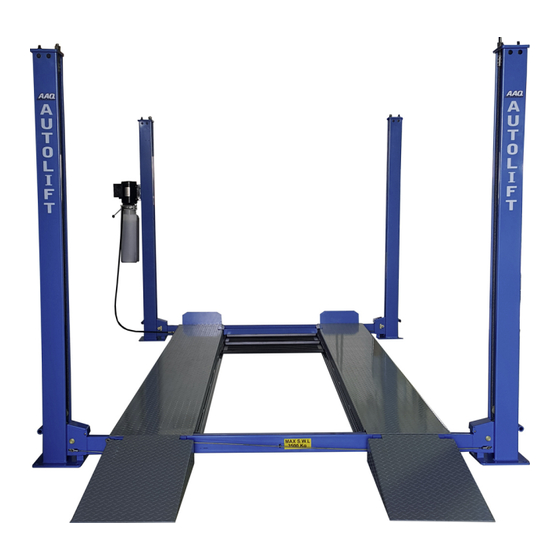
4 POST HOIST
AutoLift AL-10000T
4 Post Vehicle Hoist for Domestic & Light Mechanical Operation
3500Kg Maximum Lifting Capacity
Design Registration Approval Number: WAH21804
Design Code: AS1418.9-1996
Note: While all due care and attention has been taken in the preparation of this document, Advance AutoQuip shall not be liable for any inaccuracies or omissions
Ph: 08 9279 1663 | Fax: 08 9279 1667 | E: sales@aaq.net.au | W: www.aaq.net.au
INSTALLATION MANUAL & OPERATION
INSTRUCTIONS
- READ THE ENTIRE CONTENTS OF THIS MANUAL BEFORE
INSTALLATION AND OPERATION. BY PROCEEDING YOU AGREE THAT
YOU FULLY UNDERSTAND AND COMPREHEND THE FULL CONTENTS
OF THIS MANUAL. FORWARD THIS MANUAL TO ALL OPERATORS.
FAILURE TO OPERATE THIS EQUIPMENT AS DIRECTED MAY CAUSE
Specifications subject to change without notice.
which may occur therein
Advance AutoQuip
2 McDonald Crescent | Bassendean WA 6054
INJURY OR DEATH.
READ FIRST
DO NOT use the
machine until you read
and understand all the
dangers, warnings and
cautions in this manual.
Advertisement
Table of Contents

Related Manuals for AAQ AutoLift AL-10000T


Summary of Contents for AAQ AutoLift AL-10000T
- Page 1 Note: While all due care and attention has been taken in the preparation of this document, Advance AutoQuip shall not be liable for any inaccuracies or omissions which may occur therein Advance AutoQuip 2 McDonald Crescent | Bassendean WA 6054 Ph: 08 9279 1663 | Fax: 08 9279 1667 | E: sales@aaq.net.au | W: www.aaq.net.au...
-
Page 2: Table Of Contents
CONTENTS 1. Safety 2 - 4 1.1 Introduction 1.2 Symbols 1.3 Intended Use 1.4 Safety Instructions for Commissioning 1.5 Safety Instructions for Operation 1.6 Safety Instructions for Servicing 1.7 Safety Features 1.8 Caution Labeling Exemplify 2. Specifications 3. Packing, Transport and Storage 3.1 Lifting and handling 3.2 Storage and stacking of packages 3.3 Delivery and check of packages... -
Page 3: Safety
The hoist is designed for the safe lifting of automotive vehicles. Observe the rated load capacity below: Model No. Rated Load Capacity AutoLift AL-10000T 3500 kg 1.4 Safety Instructions for Commissioning The hoist may be installed and commissioned by authorised service personnel only. -
Page 4: Safety Instructions For Servicing
- To reduce risk of fire, do not operate equipment in the vicinity of open containers of flammable liquids(gasoline). - The main switch serves as emergency switch. In case of emergency turn to position 0. - Protect all parts of the electrical equipment from humidity and moisture. - Protect the hoist against unauthorised usage by padlocking the main switch. -
Page 5: Caution Labeling Exemplify
1.8 Caution Labeling Read operating and safety Clear area if vehicle is in manual before using hoist. danger of falling. Hoist to be used by Remain clear of hoist when trained operator only! raising or lowering vehicle. Proper maintenance and Do not override self-closing inspection is necessary hoist controls. -
Page 6: Specifications
2. Specifications 3975mm 110mm 2258mm MIN 130 MAX 1910 560mm 4760mm 4395mm 268mm 268mm 2350mm 2715mm 960mm 1910mm 890mm 475mm 4202mm Technical Specifications SPECIFICATIONS 1910... -
Page 7: Packing, Transport And Storage
3. Packing, transport and storage 3.1 Lifting and handling When loading/unloading or transporting the equipment to the site, be sure to use suitable loading (e.g. cranes, trucks) and hoisting means. When you want to move the hoist, you need to install the traversing carriages on the crossbeams and columns by using the special bolt. -
Page 8: Installation
4. Installation 4.1 Tools Required - Rotary Hammer Drill or Similar - 20mm Masonry Bit - Hammer - 1 metre Level - Open-End Wrench Set: 11mm - 28mm - Socket and Ratchet Set: 11mm - 28mm - Hex-Key / Allen Wrench Set - Large Crescent Wrench - Large Pipe Wrench - Crow Bar... -
Page 9: Foundation Dimensions / Specifications
Anchoring the posts The AutoLift AL-10000T is a portable hoist made to function without being anchored to the floor. The hoist however is designed to be anchored to the floor and we STRONGLY recommend when lifting a vehicle to anchor the hoist to the floor using the provided anchor bolts. - Page 10 4.5 Column & Cross beam Installation 1. Place a chalk line on the floor according to the floor plan layout. Pay attention to the power Unit location. Locate and stand the columns at their respective locations. DO NOT BOLT Columns down at this time. Use caution to prevent the Columns from falling over.
-
Page 11: Raising The Crossbeams
The Columns and Cross Beams will now be in position Manually raise the Cross Beams until the Primary and spaced properly for the Runways. Safety Locks engage and rest on the lock position second down from the top of the Ladder or approximately 700mm Install the Column TOP CAPS using the M12 x 2 Hex off the ground. -
Page 12: Powerside Runway Installation
4.6. Powerside Runway Installation Fig 6.4 1. Locate the Powerside Runway easily identified by the Cylinder and Sheave roller mounting structures welded on the underside. The Powerside Runway will be positioned on the side of the hoist where the power unit is installed. (See Fig. -
Page 14: Power Unit Installation & Electrical Connections
Fig 7.3 4.8 Power Unit Installation & Electrical Connections Mount the Power Unit to the Mounting Bracket using the M8 Hex Head Bolts and Nylock Nuts then fill the reservoir with 15 litres of 32 grade hydraulic oil. (See Fig. 8.1) Tighten each Nut until there is at least 25mm of threads protruding through the top of the nut. - Page 15 DANGER! DO NOT PERFORM ANY MAINTENANCE OR INSTALLATION OF ANY COMPONENTS WITH OUT FIRST ENSURING THAT ELECTRICAL POWER HAS BEEN DISCONNECTED AT THE SOURCE OR PANEL AND CANNOT BE RE-ENERGISED UNTIL ALL MAINTENANCE AND/OR INSTALLATION PROCEDURES ARE COMPLETED. IMPORTANT POWER-UNIT INSTALLATION NOTES ...
-
Page 16: Installing The Locking Device
4.9 Installing the Locking Device 1. Feed the front locking lever handle through the power post crossbeam and connect the joining rod to the threaded tube nuts and lock nuts. 2. Feed the lock lever through the rear crossbeam and connect to the joining rod and lock nuts. 3. - Page 17 After drilling, REMOVE DUST thoroughly from each hole using compressed air and/or bristle brush. Make certain that the columns remain aligned with the chalk line. Assemble the washers and nuts on the anchors then tap into each hole with a hammer until the washer rests against the base plate.
-
Page 18: Final Assembly
4.11 Final Assembly Install the approach ramps on the entry side of the hoist. Runway Stop Plate Approach ramp Install the front wheel stops at the forward side of the hoist using hex bolts, nuts and washers. Torque to 35-45 PSI. Front stop plate Locking leaver assembly Bolts (M14*85) -
Page 19: Bleeding
Repeat steps locating the target assembly at points “C” and “D” and adjusting safety ladders at each corresponding column until the reference mark on the target scale is on the cross hair of the Level. The runways are now level at all four points. (See Fig. 12.1) Fig. -
Page 20: Operation
5. Operation 5.1 Preparation - Position vehicle evenly in the center of each Runway. - Set parking brake or use wheel chock to hold vehicle in position - Before raising vehicle, be sure all personnel are clear of the hoist and surrounding area. Pay careful attention to overhead clearances. ... -
Page 21: Vehicle In Raised Position
Vehicle in Raised Position - Observe all accident prevention regulations. - Do not allow unauthorised persons to stay under the raised vehicle. - Avoid rocking of vehicle. - Keep hoist free of tools, parts, etc. Lowering During raising and lowering cycles: Closely watch the vehicle and the hoist, do not allow anyone to stay in hoist area and make sure the vehicle doors are closed. -
Page 22: Safety Operating Procedures
Safety Operating Procedures SAFETY OPERATING PROCEDURES Vehicle Hoist DO NOT use this machine unless you have been instructed in its safe use and operation and have been given permission PERSONAL PROTECTIVE EQUIPMENT Safety glasses must be worn at Long and loose hair must be Do not stand on hoist whilst all times in work areas. -
Page 23: Operation Instructions
Do not attempt to maneuver the hoist with a vehicle on it. Doing so may cause injury to personnel. MODEL: SERIAL NO.: APPROVAL No. AutoLift AL-10000T WAH21804 www.aaq.net.au For service PH: 08 9279 1663... -
Page 24: Maintenance
6. Maintenance Turn off and lock the main switch before servicing the hoist. The maintenance intervals indicated below apply to average workshop use. The hoist should be inspected more frequently for high use application. 6.1 Maintenance Schedule Establish a periodic preventive maintenance procedure to ensure trouble-free operation and long service life. DAILY: - Raise and lower the hoist (with no vehicle) at the beginning of each shift to verify the runways are level and that the hoist is operating properly. - Page 25 4. Slightly grease the slide tracks over their whole length using a brush. HOIST STABILITY 1 Every six months check the nuts of all anchor bolts for correct installation torque T 2 Retighten them as required. Installation Torque T AutoLift AL-10000T 80 Nm...
-
Page 26: Troubleshooting Guide
6.3 Troubleshooting Guide The following are suggestions to consider if you have problems with the hoist. Please call a qualified hoist technician and/or a qualified electrician for further clarification and information. HOIST WILL NOT RAISE POSSIBLE CAUSE REMEDY INSTRUCTION 1. Check for proper oil level The oil level should be up to the 1. - Page 27 MOTOR WILL NOT RUN POSSIBLE CAUSE REMEDY INSTRUCTION 1. Check for correct voltage Compare supply voltage with voltage on motor name plate. 1. Fuse blown, (5,2,1,3,4) Check that the wire is sized correctly. Requires 18 Amp Circuit Breaker . 2. Limit switch burned out, 2.
- Page 28 HOIST WILL NOT STAY UP POSSIBLE CAUSE REMEDY INSTRUCTION The oil level should be up to 1. Check oil level 1. Air in oil, (1,2,3) bleed screw with hoist down. 2. Oil seal damaged and cocked Replaced oil seal around pump 2.
- Page 29 HOIST WILL NOT RAISE POSSIBLE REMEDY INSTRUCTION CAUSE 1. Air in oil, (1,2,3,4) The oil level should be up to the 1.Check oil level bleed screw in the reservoir with the hoist all the way down. 2. Cylinder binding, (5) 2. Check/Tighten inlet tubes Replace inlet hose assembly.
-
Page 30: Explosion Diagrams And Parts List
7. Explosion Diagrams and Parts List 7.1 Explosion Diagrams 曹营... - Page 31 气飞...
- Page 34 f封 建...
- Page 36 Do not attempt to maneuver the hoist with a vehicle on it. Doing so may cause injury to personnel. MODEL: SERIAL NO.: APPROVAL No. AutoLift AL-10000T WAH21804 www.aaq.net.au For service PH: 08 9279 1663...
-
Page 37: Warranty
8. Warranty . F 8 ’S I L I I F I I F I I S I STRUCTURAL COMPONENTS: ALL STRUCTURAL AND MECHANICAL COMPONENTS OF THIS UNIT ARE GUARANTEED FOR A PERIOD OF FIVE YEARS, FROM THE DATE OF INVOICE, AGAINST DEFECTS IN WORKMANSHIP AND/OR MATERIALS WHEN HOIST IS INSTALLED AND USED ACCORDING TO RECOMMENDATIONS. - Page 38 COMMISSIONING REPORT 1. Details of Customer Customer Name: Installation Address: 2. Hoist Details Model No: 2 McDonald Crescent Hoist Type: Bassendean WA 6054 Installation Date: P: 08 9279 1663 | E: sales@aaq.net.au 3. Commissioning Report Comments Safety Devices Safety devices incorporated into the design of the vehicle to AS/NZS 1418.9 Welds Visual check all welds completed and comply to requirement of AS/NZS 1554 Hydraulic Equipment and Controls Visual check carried out for leaks Pneumatic Equipment and Controls Visual check carried out for leaks Safety Locks Safety locks tested for correct operation Support Pads Checked for good working order Wheel Stops Supplied with the hoist and in good working order Hoist Motion Limits Checked for correct operation Load Test and Speed Check Hoist checked with load for correct operation and speed control tested Wire Ropes Checked wire ropes for correct installation and tension Concrete Floor Concrete floor is a suitable depth for installation...
- Page 39 COMMISSIONING REPORT Location of Vehicle Hoist & Vehicle Clearances Vehicle hoist or any part of the load is positioned no less than 600mm away from any fixed structure Provisions have been made for effective clearances above the vehicle when the hoist is in its fully raised position. Markings ‐ Hoist Checked for Relevant Marking Including: Make & Model Number Serial number Rated Capacity Reference to maintenance Operation instructions Screw and Nut Gaps Hoist compliance plate showing design registration Functional Test Vehicle hoist has been tested and all safety devices, limit switches and control function interlocks have been tested for correct operation. Demonstration The installer has demonstrated the operation of the vehicle hoist to the owner or operator Electrical Equipment and Controls Lock off isolating switch installed Emergency stop button installed 3. Details of Electrical Contractor Trading Name: EC Licence Number: Address: Telephone Number: 4. Signature Name: ___________________________________________________________ Date: I, being the person responsible for completing the commissioning report have exercised reasonable skill and competency when completing the report and herby certify that the vehicle hoist has been commissioned fit for use as per the Australian / New Zealand Standard 1418.9:1996 Vehicle Hoists.
Need help?
Do you have a question about the AutoLift AL-10000T and is the answer not in the manual?
Questions and answers