Table of Contents
Advertisement
Quick Links
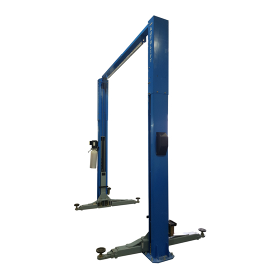
2 POST HOIST
AutoLift AL-9500HD
Symmetric 2 Post Clearfloor Vehicle Hoist
4000Kg Maximum Lifting Capacity
Design Registration Approval Number: WAH22688
Design Code: AS1418.9-1996
Note: While all due care and attention has been taken in the preparation of this document, Advance AutoQuip shall not be liable for any inaccuracies or omissions
Ph: 08 9279 1663 | Fax: 08 9279 1667 | E: sales@aaq.net.au | W: www.aaq.net.au
INSTALLATION MANUAL & OPERATION
INSTRUCTIONS
- READ THE ENTIRE CONTENTS OF THIS MANUAL BEFORE
INSTALLATION AND OPERATION. BY PROCEEDING YOU AGREE THAT
YOU FULLY UNDERSTAND AND COMPREHEND THE FULL CONTENTS
OF THIS MANUAL. FORWARD THIS MANUAL TO ALL OPERATORS.
FAILURE TO OPERATE THIS EQUIPMENT AS DIRECTED MAY CAUSE
Specifications subject to change without notice.
which may occur therein
Advance AutoQuip
2 McDonald Crescent | Bassendean WA 6054
INJURY OR DEATH.
READ FIRST
DO NOT use the
machine until you read
and understand all the
dangers, warnings and
cautions in this manual.
Advertisement
Table of Contents

Related Manuals for AAQ AutoLift AL-9500HD


Summary of Contents for AAQ AutoLift AL-9500HD
- Page 1 Note: While all due care and attention has been taken in the preparation of this document, Advance AutoQuip shall not be liable for any inaccuracies or omissions which may occur therein Advance AutoQuip 2 McDonald Crescent | Bassendean WA 6054 Ph: 08 9279 1663 | Fax: 08 9279 1667 | E: sales@aaq.net.au | W: www.aaq.net.au...
- Page 2 Printing characters and symbols Throughout this manual, the following symbols and printing characters are used to facilitate reading: Indicates the operations which need proper care Indicates prohibition Indicates a possibility of danger for the operators. Indicates the direction of access for motor vehicles to the hoist BOLD TYPE Important information WARNING: Before operating the hoist and carrying...
- Page 3 Index 10.0 Hydraulic System Diagram 1.0 General Information 1.1 Manual keeping Obligation case of malfunction 11.0 Balance Rope Diagram Cautions for the safety of the operator Warnings 12.0 Maintenance 2.0 Product Identification 12.1 Every Week 2.1 Warranty certificate 12.2 Every Month Technical servicing 12.2 Every 200 Hours Running 3.0 Transport &...
-
Page 4: Chapter 1 - General Information
Chapter 1 – General information This chapter contains warning instructions to operate the hoist properly and prevent injury to operators or objects. This manual has been written to be used by shop technicians in charge of the hoist (operator) and routine maintenance technician (maintenance operator). The operating instructions are considered to be an integral part of the machine and must remain with it for its whole useful life. - Page 5 1.3 Cautions for the safety of the operator Operators must not be under the influence of sedatives, drugs or alcohol when operating the machine. Before operating the hoist, operators must be familiar with the position and function of all controls, as well as with the machine features shown in the chapter “Operation and use”...
-
Page 6: Chapter 2 - Product Identification
Chapter 2 – Product identification The identification data of the machine are shown in the label placed on the control unit. Two Post Vehicle Hoist 240V, 1Ph Model No. AL-9500HD Power Supply 415V, 3Ph Lift Height(mm) 1910 Power(Kw) Capacity(Kg) 4500 Air Pressure(Mpa) NW(Kg) GW(Kg) -
Page 7: Chapter 3 - Packing, Transport And Storage
Chapter 3 – Packing, transport and storage Only skilled personnel who are familiar with the hoist and this manual shall be allowed to carry out packing, lifting, handling, transport and unpacking operations. 3.1 Transport and package removal ATTENTION: moving and positioning operations can be very dangerous if not performed with the utmost caution. -
Page 8: Chapter 4 - Product Description
Chapter 4 – Product description The hoist is composed by two symmetric vertical posts, which must be safely anchored to the ground. The posts are equipped with lifting carriages with electro-hydraulic control system. The hoist is operated by an electric motor controlling a hydraulic pump, which delivers the hydraulic fluid to the cylinders at the bottom of the posts for lifting carriages with the sole purpose of performing motor vehicle service, repairing and inspection. - Page 9 4.1 Dimensional diagrams Dimensions / HOIST SPECIFICATIONS 3900mm High Setting OR 4900mm Extra High Setting (with optional extensions) 3750mm High Setting...
- Page 10 1140 1350 3550 2505 3615...
-
Page 11: Control Board
5.0 Introduction 5.1 Control Board WALL WALL Vehicle Enter WALL ( ) Fig 1... -
Page 12: General Safety Rules
6.0 General safety rules 6.1 Level of Danger Whenever you find the following warning sign in this guide, pay the utmost attention and follow the relevant safety rules. ATTENTION: Read the following directions with the utmost attention. The non-observance of what described can cause serious damage to bystanders. - Page 13 6.0 General safety rules 6.2 Hazard and Forbidden Operation WARNINGS DO NOT MODIFY ANY SAFETY SYSTEMS OF HOIST IF SAFETY DEVICE MALFUNCTIONS, SERIOUS ACCIDENT MAY OCCUR DO NOT OPERATE HOIST WHEN WIRE ROPE DAMAGE IS DETECTED DO NOT SHAKE A RAISED VEHICLE EXCESSIVELY DANGER OF VEHICLE FALL FROM HOIST MAY OCCUR POSITION VEHICLE WITH CENTER OF GRAVITY MIDWAY BETWEEN ADAPTERS...
- Page 14 6.0 General safety rules 6.3 Caution HOIST TO BE USED BY TRAINED OPERATOR ONLY ELECTRICAL SHOCK MAY EXIST WHEN OPENING A CONTROL BOX AUTHORIZED PERSONNEL ONLY IN HOIST AREA ALWAYS USE SAFETY STANDS WHEN REMOVING OR INSTALLING HEAVY COMPONENTS DO NOT HOSE WATER DIRECTLY ONTO HOIST STOP RAISING HOIST WHEN IMBALANCE IS DETECTED WHILE RASING VEHICLE...
- Page 15 6.0 General safety rules 6.3 Caution USE VEHICLE MANUFACTURER'S LIFT POINTS USE HEIGHT EXTENDERS WHEN NECESSARY TO ENSURE GOOD CONTACT DO NOT OPERATE HOIST WHEN HYDRAULIC OIL LEAK IS DETECTED AUXILIARY ADAPTERS MAY REDUCE LOAD CAPACITY...
-
Page 16: Safety Instruction
6.0 General safety rules 6.4 Safety Instruction The messages and pictographs shown are generic in nature and are meant to generally represent hazards common to all automotive hoists regardless of specific style. Warning Labels for 2-Post surface mounted hoists. Daily review of these Safety Messages and Warnings is suggested. -
Page 17: Chapter 7 Installation
Chapter 7 Installation Only skilled technicians, appointed by the manufacturer, or by authorized dealers, must be allowed to carry out installation. Serious damage to people and to the hoist can be caused if installations are made by unskilled personnel. Before carrying out any operations, remember to insert the safety piece of wood between the lower booms and the base frame. - Page 18 7.4 Installation Procedure MPORTANT OOLS MINIMUM Always wear safety glasses while installing hoist. REQUIRED Tape measure, 5m Chalk line 1200mm level Carpenters Square 10” adjustable wrench Open end wrenches 14mm,16mm,17mm,19mm Needle Nose pliers Snap Ring pliers Screw Drivers (Flat and Phillips) Hammer drill w/ 20mm diameter carbide-tipped bits 2lb hammer Torque wrench: 150 ft.-lbs.
- Page 19 4) Assemble Overhead Mounting Bracket to the NCHORING Column Extension using (4 sets) M12 x 25 Hex 7) The anchor bolts must be installed at least bolts, flat washers, lock washers, and nuts. 200mm from any crack, edge, or expansion joint. Repeat for opposite bracket and extension.
- Page 20 16) Use 2 sets M10X20 bolt, nut, flat washer,Install VERHEAD bracket to the head Beam on the Idler side of the 14) Assemble two Overhead beams using (6 sets) hoist. See Fig 7b: M10 x 20 bolt, nut, flat washer, and lock washer as shown in Fig 6.
- Page 21 23) Route other end of cable up and over sheave in NCHORING Overhead. Follow across to sheave on opposite 18) Check Idler Column shimming. Column. Route cable down through Column to additional shims (see Fig 5) to remove any top mounting plate in Carriage. Attach cable to gaps that may have been created while Carriage top plate as seen in Fig 9c with (2) installing Overhead.
- Page 22 27) Assemble Power Unit, Tee Fitting, and hoses YDRAULIC OSES together as shown in Fig 13. Use (4 sets) M8 bolt, nut, 25) Attach Power Hose to Cylinder Fitting at the flat washer, and lock washer to attach Power Unit to bottom of the Power Column as shown in Fig 11 column bracket. below. Repeat with longer Idler Hose and Idler Column. If hoist is installed in the “Tall Height” setting, use Hose Extension and Hose Extension Fitting between Idler Hose and Cylinder Fitting.
- Page 23 IDLER SIDE BEAM SIDE Fig 14– Hydraulic Hose Routing ELEASE 29) While the carriages are still sitting in the locks from the previous steps, route the Lock Release Cable assembly (Loop End) through the Idler Column opening, around the pulley and attach to the Lock Release Cam as seen on next page.
- Page 25 3 ) Extend the Foot Pad to both extents and apply “anti-seize” to the three retaining rings and where the double screw makes contact with the base of the Foot Pad.
-
Page 26: Electrical Connections
8.0 Electrical Connections 8.1 Electrical connection with diagrams CAUTION: Electric motor jumper pin connections 240v & 415v... -
Page 27: Electrical Connection
8.0 Electrical connection 8.2 Connection to the power sources Any work on the electrics, however small, must be carried out by qualified electrician only. The hoist power supply is 5-core AC, 415V, 50Hz unless otherwise required by the user. The power lead must be protected against the over current by means of fuses or by means of a isolator switch with nominal values as indicated by the chart here below: FEEDING VOLTAGE FUSE NOMINAL VALUE... -
Page 28: Check Of Safety Devices
9.0 Check Of Safety Devices ATTENTION: The following devices shall not be tampered or cut out. They must be kept in a perfect condition of efficiency: 9.1 Check of rubber pads Check their condition and, if worn or broken, replace them. 9.2 Safety lock engagement button Press up button, raise hoist to desired height, press the lock arm and check that the carriages stop on the first available lock position;... -
Page 29: Hydraulic System Diagram
10.0 Hydraulic System Diagram... - Page 30 11.0 Balance Rope Diagram...
-
Page 31: Maintenance
12.0 Maintenance The several maintenance operations to be carried out are described below. A low operation cost and a long life of the machine depends from constant observation of the operations. CAUTION: The listed intervention times are given for information and they refer to normal operating conditions. - Page 32 12.0 Maintenance GREASE THE MACHINE EVERY 500 WORKING CYCLES Grease internal post Note : The given points refer to both left and right post : (Internal) sides of each runway it is advisable to use Lithium or EP Calcium grease.
-
Page 33: Parts List
13.0 Parts List... -
Page 37: Optional Accessories
14 Optional accessories 14.1 4WD & Light duty commercial 4” extension pads In some situations the standard pads cannot make contact with the vehicle pick up points. For example: 4WD vehicles with side steps, light duty commercial vehicles with high chassis. Our 9500LS has the optional 4WD &... - Page 38 When the vehicle is lowered to the lowest position swing the lifting arms away from the vehicle to the rest position. Turn the power off. MODEL APPROVALS: SERIAL NO: AutoLift WAH22688 AL9 00HD Design Code: AS1418.9 -1996 WWW.AAQ.NET.AU...
- Page 39 SAFETY OPERATING PROCEDURES Vehicle Hoist DO NOT use this machine unless you have been instructed in its safe use and operation and have been given permission PERSONAL PROTECTIVE EQUIPMENT Safety glasses must be worn at Long and loose hair must be Do not stand on hoist whilst all times in work areas.
- Page 40 SEALS, VEE BELTS AND SLIDING BLOCKS. THIS WARRANTY SUPERSEDES ALL OTHER WARRANTY POLICIES PREVIOUSLY STATED AND IN ALL OTHER ADVANCE AUTOQUIP’s PRODUCT SPECIFIC LITERATURE. Advance AutoQuip 2 McDonald Crescent | Bassendean WA 6054 Ph: 08 9279 1663 |E: sales@aaq.net.au | W: www.aaq.net.au...
- Page 41 2. Hoist Details Model No: 2 McDonald Crescent Hoist Type: Bassendean WA 6054 Installation Date: P: 08 9279 1663 | E: sales@aaq.net.au 3. Commissioning Report Comments Safety Devices Safety devices incorporated into the design of the vehicle to AS/NZS 1418.9 Welds...
- Page 42 COMMISSIONING REPORT Location of Vehicle Hoist & Vehicle Clearances Vehicle hoist or any part of the load is positioned no less than 600mm away from any fixed structure Provisions have been made for effective clearances above the vehicle when the hoist is in its fully raised position.
Need help?
Do you have a question about the AutoLift AL-9500HD and is the answer not in the manual?
Questions and answers