Table of Contents
Advertisement
Quick Links
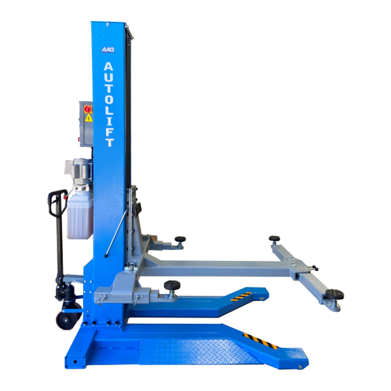
SINGLE POST HOIST
AutoLift AL-167251
Single Post Portable Hoist
2500Kg Maximum Lifting Capacity
Design Registration Approval Number: WAH22059
Design Code: AS1418.9-1996
Note: While all due care and attention has been taken in the preparation of this document, Advance AutoQuip shall not be liable for any inaccuracies or omissions
Ph: 08 9279 1663 | Fax: 08 9279 1667 | E: sales@aaq.net.au | W: www.aaq.net.au
INSTALLATION MANUAL & OPERATION
INSTRUCTIONS
- READ THE ENTIRE CONTENTS OF THIS MANUAL BEFORE
INSTALLATION AND OPERATION. BY PROCEEDING YOU AGREE THAT
YOU FULLY UNDERSTAND AND COMPREHEND THE FULL CONTENTS
OF THIS MANUAL. FORWARD THIS MANUAL TO ALL OPERATORS.
FAILURE TO OPERATE THIS EQUIPMENT AS DIRECTED MAY CAUSE
Specifications subject to change without notice.
which may occur therein
Advance AutoQuip
2 McDonald Crescent | Bassendean WA 6054
INJURY OR DEATH.
READ FIRST
DO NOT use the
machine until you read
and understand all the
dangers, warnings and
cautions in this manual.
Advertisement
Table of Contents

Related Manuals for AAQ AutoLift AL-167251


Summary of Contents for AAQ AutoLift AL-167251
- Page 1 Note: While all due care and attention has been taken in the preparation of this document, Advance AutoQuip shall not be liable for any inaccuracies or omissions which may occur therein Advance AutoQuip 2 McDonald Crescent | Bassendean WA 6054 Ph: 08 9279 1663 | Fax: 08 9279 1667 | E: sales@aaq.net.au | W: www.aaq.net.au...
- Page 2 1. Important safety instructions……………………………….…………………..3~4 1.1 Important notices 1.2 Qualified personnel 1.3 Danger notices 1.4 Training 1.5 Warning signs 2. Overview of the hoist……………………………………………………………….…..5 2.1 General descriptions 2.2 Technical data 2.3 Construction of the hoist 3. Installation instructions…………………………………………………………..6~13 3.1 Preparations before installation 3.2 Precautions for installation 3.3 Installation 3.4 Items to be checked after installation...
-
Page 3: Important Safety Instructions
1.1 Important notices AAQ Australia will offer one-year's quality warranty for the whole machine, during which any quality problem will be properly solved to the user's satisfaction. However, we will not take any responsibility for whatever bad consequence resulted from improper installation and operation, overload running or unqualified ground condition. -
Page 5: General Descriptions
OVERVIEW OF THE HOIST 2.1 General descriptions This single post hoist is composed of base frame, post, carriage, lifting arms, cylinders, portable kit and motor unit, etc. It is driven by an electro-hydraulic system. The gear pump delivers hydraulic oil to oil cylinders and pushes upwards its piston. The piston drives the chain to raise the carriage and the lifting arms. -
Page 6: Ground Conditions
INSTALLATION INSCRUCTIONS 3.1 Preparations before installation 3.1.1 Tools and equipments needed Appropriate lifting equipment Anti-abrasion hydraulic oil. Rotary Hammer Drill with 3/4’’ drill bit. Chalk and tape measure, magnetic plump, 8 metersФ15 level pipe. Sockets and open wrenches, a set of inside hex wrenches, cross and straight screw drivers. ... - Page 7 Step 5: Install the lifting platforms and lifting arms 1. Fix the lifting platform onto the carriage.
- Page 8 2.Connect lifting arms and the lifting platform. 2. Fix limit switches into the power side post.
-
Page 9: Items To Be Checked After Installation
3.4 Items to be checked after installation. Check items Is the post vertical to the floor? Is the oil hose well connected? Is the steel cable well connected? Are all lifting arms well fixed? Are electrical connections right? Are the rest joints firmly screwed? Are all items need lubricating added with grease? OPERATION INSTRUCTIONS 4.1 Precautions... -
Page 10: Troubleshooting
Raise the hoist 1.Make sure that you have read and understood the operation manual before operation. 2.Park the car on smooth and solid ground and then move the hoist with its lifting platform located beneath the car. 3.Adjust the lifting arms until they reach the supporting positions of the vehicle and make sure the gravity of vehicle located mid way four lifting arms. -
Page 11: Maintenance
slowly after being The oil cylinder is not tightened. Replace the seal. raised The single valve leaks. Clean or replace it. Solenoid valve fails to work well. Clean or replace it. Steel cable is loose or not with same tightness Check and adjust the tightness. - Page 12 ·Check if arm lock works well or not. 6.2. Weekly checking items ·Check the flexibility of moving parts. ·Check the working conditions of safety parts. ·Check the amount of oil left in the oil tank. Oil is enough if the carriage can be raised to highest position. Otherwise, oil is insufficient.
- Page 13 Material # Name Drawing# Property Note Spring washer Standard Hex nut Standard Rod of chain protection cloth 8224E-A1-B5 Zinc-plating Hex nut Standard Cross socket cap head screw M5*10 Standard Cross socket cap head screw M6*16 Standard Electromagnet Assembly Safety locking plate 8224E-A13 Zinc-plating Positioning block...
- Page 14 Annex2, Overall diagram...
- Page 15 Annex 3, Hydraulic working system 1.Drive oil cylinder 3.Solenoid unloading valve 4.Throttle valve 5.Motor 6.Coupling 7.Gear pump 8.Single –way valve 9.Over-flow valve 10.Anti-surge valve 11.Cushion valve 12. Emergency unloading valve Name Motor Hydraulic block Overflow valve Removable plug Cushion valve Oil absorbing pipe Oil filter Throttle valve...
- Page 16 Annex4, Wiring diagram Single phase...
- Page 17 Three phase...
- Page 19 Annex5, Separated drawings for the hoist Material # Name Drawing# Property Note Base frame 812E-A1-B1 Powder-coating Ramp A 812FE-A1-B2 Powder-coating Cross socket flat head screw M8*12 Standard Roller shaft 812E-A1-B2 Zinc-plating Nylon roller 812E-A1-B3 Nylon...
- Page 20 Material # Name Drawing# Property Note Post (portable type ) 812E-A2-B1 Powder-coating Wire&hose cover 812FE-A2 Powder-coating cross socket cap head screw M5*30 Standard Oil hose clip (small) Zinc-plating Cross socket cap head screw M5*8 Standard Limit switch 8108 Electric Power unit Assembly Hex head full swivel screw M10*35 Standard...
- Page 21 Material # Name Drawing# Property Note Short oil hose 812FE-A10 Assembly Control box Assembly Cross socket cap head screw M5*10 Standard Hex socket cylindrical screw Standard M12*20 Flat washer M12 Standard Top plate 812FE-A5 Powder-coating 812 right -angle connector 812FE-A11 long oil hose 812FE-A9 Assembly...
- Page 22 Material # Name Drawing# Property Note Lifting platform 812FE-A4-B1 Powder-coating Drawable platform 812E-A4-B2 Powder-coating Front arm A 812E-A4-B3-C1 Powder-coating Hex nut M16 Standard Front arm B 812FE-A4-B3-C2 Powder-coating Cross socket flat head screw M8*12 Standard Front arm C 812FE-A4-B3-C3 Powder-coating Assembly Lifting tray 8224E-A7-B4...
- Page 23 Material # Name Drawing# Property Note M10*20 Rear arm B 812FE-A4-B4-C2 Powder-coating Rear arm C 812FE-A4-B4-C3 Powder-coating Cross socket flat head screw M8*12 Standard Circlip D22 Standard Elastic cylindrical pin M5*35 Standard Circlip D38 Standard Shaft 8224E-A12 Zinc-plating Pressure spring 8224E-A2-B4 Zinc-plating Pulling rod...
- Page 24 Material # Name Drawing# Property Note Bearing 2548 Standard Circlip D25 Standard Carriage 812FE-A3-B1 Powder-coating 612 big slider 812FE-A3-B2 Nylon 612 small slider 812FE-A3-B3 Nylon Hex socket cylinder head screw M6*30 Standard Tube 8225E-A3-B2 Zinc-plating Hex socket cylinder head screw M10*20 Powder-coating Chain LH1246...
- Page 25 Annex 6, Spare parts list Spare parts for electrical system Material # Name Spec. Pic. Note Power switch LW26GS-20/04 Button Y090-11BN Power indicator AD17-22G-AC24 JBK3-160VA380V-24V Transformer JBK3-160VA220V-24V AC contactor CJX2-1210/AC24 DZ47-63 C16/3P Circuit breaker DZ47-63 C32/2P Circuit breaker DZ47-63 C3/1P Limit switch TZ8108 Emergency stop...
- Page 26 Material # Name Spec. Pic. Note Relay holder PTF-08A Time relay ST6PA-5S/AC24V Time relay holder PYF-08AE Control box 260*460*135 Spare parts for the mechanical system Material # Name Drawing# Property Note Deep groove ball bearing Standard Standard (with anti-dust cover) 612 slider 612FE-A3-B3 Nylon 1010...
- Page 28 SAFETY OPERATING PROCEDURES Vehicle Hoist DO NOT use this machine unless the operator has been thoroughly instructed in its safe use and operation. Safety glasses must be worn at all Long and loose hair must be times in work areas. contained.
- Page 29 THIS WARRANTY SUPERSEDES ALL OTHER WARRANTY POLICIES PREVIOUSLY STATED AND IN ALL OTHER ADVANCE AUTOQUIP’s PRODUCT SPECIFIC LITERATURE. Advance AutoQuip 2 McDonald Crescent | Bassendean WA 6054 Ph: 08 9279 1663 | Fax: 08 9279 1667 | E: sales@aaq.net.au | W: www.aaq.net.au...
-
Page 30: Commissioning Report
COMMISSIONING REPORT 1. Details of Customer Customer Name: Installation Address: 2. Hoist Details Model No: 2 McDonald Crescent Hoist Type: Bassendean WA 6054 Installation Date: P: 08 9279 1663 | E: sales@aaq.net.au 3. Commissioning Report Comments Safety Devices Safety devices incorporated into the design of the vehicle to AS/NZS 1418.9 Welds Visual check all welds completed and comply to requirement of AS/NZS 1554 Hydraulic Equipment and Controls Visual check carried out for leaks Pneumatic Equipment and Controls Visual check carried out for leaks Safety Locks Safety locks tested for correct operation Support Pads Checked for good working order Wheel Stops Supplied with the hoist and in good working order Hoist Motion Limits Checked for correct operation Load Test and Speed Check Hoist checked with load for correct operation and speed control tested Wire Ropes Checked wire ropes for correct installation and tension Concrete Floor Concrete floor is a suitable depth for installation... - Page 31 COMMISSIONING REPORT Location of Vehicle Hoist & Vehicle Clearances Vehicle hoist or any part of the load is positioned no less than 600mm away from any fixed structure Provisions have been made for effective clearances above the vehicle when the hoist is in its fully raised position. Markings ‐ Hoist Checked for Relevant Marking Including: Make & Model Number Serial number Rated Capacity Reference to maintenance Operation instructions Screw and Nut Gaps Hoist compliance plate showing design registration Functional Test Vehicle hoist has been tested and all safety devices, limit switches and control function interlocks have been tested for correct operation. Demonstration The installer has demonstrated the operation of the vehicle hoist to the owner or operator Electrical Equipment and Controls Lock off isolating switch installed Emergency stop button installed 3. Details of Electrical Contractor Trading Name: EC Licence Number: Address: Telephone Number: 4. Signature Name: ___________________________________________________________ Date: I, being the person responsible for completing the commissioning report have exercised reasonable skill and competency when completing the report and herby certify that the vehicle hoist has been commissioned fit for use as per the Australian / New Zealand Standard 1418.9:1996 Vehicle Hoists.
Need help?
Do you have a question about the AutoLift AL-167251 and is the answer not in the manual?
Questions and answers