Table of Contents
Advertisement
Quick Links
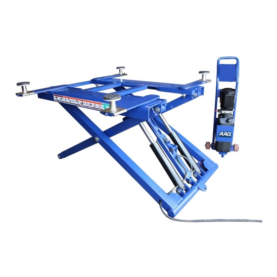
SCISSOR HOIST
AutoLift AL-3060
2700Kg Maximum Lifting Capacity
Note: While all due care and attention has been taken in the preparation of this document, Advance AutoQuip shall not be liable for any inaccuracies or omissions
INSTALLATION MANUAL & OPERATION
INSTRUCTIONS
For Domestic
Use Only
- READ THE ENTIRE CONTENTS OF THIS MANUAL BEFORE
INSTALLATION AND OPERATION. BY PROCEEDING YOU AGREE THAT
YOU FULLY UNDERSTAND AND COMPREHEND THE FULL CONTENTS
OF THIS MANUAL. FORWARD THIS MANUAL TO ALL OPERATORS.
FAILURE TO OPERATE THIS EQUIPMENT AS DIRECTED MAY CAUSE
Specifications subject to change without notice.
2 McDonald Crescent | Bassendean WA 6054
Ph: 08 9279 1663 | Fax: 08 9279 1667 | E: sales@aaq.net.au | W: www.aaq.net.au
INJURY OR DEATH.
which may occur therein
Advance AutoQuip
READ FIRST
DO NOT use the
machine until you read
and understand all the
dangers, warnings and
cautions in this manual.
Advertisement
Table of Contents

Related Manuals for AAQ AL-3060


Summary of Contents for AAQ AL-3060
- Page 1 Note: While all due care and attention has been taken in the preparation of this document, Advance AutoQuip shall not be liable for any inaccuracies or omissions which may occur therein Advance AutoQuip 2 McDonald Crescent | Bassendean WA 6054 Ph: 08 9279 1663 | Fax: 08 9279 1667 | E: sales@aaq.net.au | W: www.aaq.net.au...
- Page 2 Printing characters and symbols Throughout this manual, the following symbols and printing characters are used to facilitate reading: Indicates the operations which need proper care Indicates prohibition Indicates a possibility of danger for the operators. Indicates the direction of access for motor vehicles to the lift BOLD TYPE Important information WARNING: before operating the lift and carrying out any adjustment, read carefully chapter 7 “instruction” where all proper operations for a better functioning of the lift are shown. ...
-
Page 3: Table Of Contents
Contents Chapter 1 – General information ............................ 5 1.1 Manual keeping .............................. 5 1.2 Obligation case of malfunction ......................... 5 1.3 Cautions for the safety of the operator ...................... 5 1.4 Warnings ................................ 6 Chapter 2 – Product identification .......................... 7 2.1 Warranty certificate ............................ 7 2.2 Technical servicing ............................. 7 Chapter 3 – Packing, transport and storage ........................ 8 3.1 Transport and package removal ........................ 8 3.2 Lifting and handling ... - Page 4 9.2 Periodic maintenance ............................ 2 3 Chapter 10 Trouble shooting ............................ 2 4 Chapter 11 Disposal of used oil ............................. 2 5 Chapter 12 Machine demolition ........................... 2 5 ...
-
Page 5: Chapter 1 -General Information
Chapter 1 –General information This chapter contains warning instructions to operate the lift properly and prevent injury to operators or objects. This manual has been written to be used by shop technicians in charge of the lift (operator) and routine maintenance technician (maintenance operator). The operating instructions are considered to be an integral part of the machine and must remain with it for its whole useful life. Read every section of this manual carefully before operating the lift and unpacking it since it gives helpful information about: SAFETY OF PEOPLE SAFETY OF THE LIFT SAFETY OF LIFTED VEHICLES The company is not liable for possible problems, damages, accidents, etc. resulting from failure to follow the instructions contained in this manual. Only skilled technicians of AUTHORISED DEALERS or SERVICE CENTERS AUTHORISED by the manufacturer shall be allowed to carry out lifting, transport, assembling, installation, adjustment, calibration, settings, extraordinary maintenance, repairs, overhauling and dismantling of the lift. THE MANUFACTURER IS NOT RESPONSIBLE FOR POSSIBLE DAMAGE TO PEOPLE, VEHICLES OR OBJECTS IF SAID OPERATIONS ARE CARRIED OUT BY UNAUTHORIZED PERSONNEL OR THE LIFT IS IMPROPERLY USED. Any use of the machines made by operators who are not familiar with the instructions and procedures contained herein shall be forbidden. ... -
Page 6: Warnings
1.4 Warnings Unauthorized changes and/or modifications to the machines relieve the manufacturer of any liability for possible damages to objects or people. Do not remove or make inoperative the safety devices, this would cause a violation of safety at work laws and regulations. Any other use which differs from that provided for by the manufacturer of the machine is strictly forbidden. The use of non genuine parts may cause damage to people or objects. DECLARATION OF WARRANTY AND LIMITATION OF LIABILITY The manufacturer has paid proper attention to the preparation of this manual. However, nothing contained herein modifies or alters, in any way, the terms and conditions of manufacturer agreement by which this lift was acquired, nor increase, in any way, manufacturer’s liability to the customer. TO THE READER Every effort has been made to ensure that the information contained in this manual is correct, complete and up‐to date. The manufacturer is not liable for any mistakes made when drawings up this manual and reserves the right to make any changes due the development of the products, at any time. ... -
Page 7: Chapter 2 - Product Identification
Chapter 2 – Product identification The identification data of the machine are shown in the label placed on the control unit. Use the above data both to order spare parts and when getting in touch with the manufacturer (inquiry). The removal of this label is strictly forbidden. Machines may be updated or slightly modified from an aesthetic point of view and, as a consequence, they may present different features fro these shown, this without prejudicing what has been described herein. 2.1 Warranty certificate The warranty is valid for a period of 12 months starting from the date of the purchase invoice. The warranty will come immediately to an end when unauthorized modifications to the machine or parts of it are carried out. The presence of defects in workmanship must be verified by the Manufacturer’s personnel in charge. 2.2 Technical servicing For all servicing and maintenance operations not specified or shown in these instructions, contact your Dealer where the machine has been bought or the Manufacturer’s Commercial Department. ... -
Page 8: Chapter 3 -Packing, Transport And Storage
Chapter 3 –Packing, transport and storage Only skilled personnel who are familiar with the lift and this manual shall be allowed to carry out packing, lifting, handling , transport and unpacking operations. 3.1 Packing The packing of the lift is delivered in following components: N.2 base units packed in a steel frame, wrapped up in non‐scratch waterproof material and sealed with 2 straps. N.1 power unit packed in a plywood box N.4 drive‐on ramps wrapped up in non‐scratch waterproof material, including N.4 rubber pads. No.3hydraulic hoses and N.8 anchor bolts. (If requested, optional accessories are available to satisfy each customer’s requirements) The average weight of the package is 920kg. 3.2 Lifting and handling When loading/unloading or transporting the equipment to the site, be sure to use suitable loading(e.g. cranes, trucks) and hoisting means. Be sure also to hoist and transport the components securely so that they cannot drop, taking into consideration the package’s size, weight and centre of gravity and it’s fragile parts. Hoist and handle only one package at a time 3.3 Storage and stacking of packages Packages must be stored in a covered place, out of direct sunlight and in low humidity, at a temperature between ‐10℃ and +40℃. Stacking is not recommended: the package’s narrow base, as well as its considerable weight and size make it difficult and hazardous. 3.4 Delivery and check of packages ... -
Page 9: Chapter 4 -Product Description
Chapter 4 –Product description 4.1 Dimensional diagrams Dimensions / Z3060 ... -
Page 10: Parts List
4.2 Parts List 1 Outside arm assembly 2 Inner arm and axle 3 Axle circlip 25 4 Safety assembly 5 Safety lock shaft 6 Safety shaft 7 Safety shaft 8 Axle circlip 20 9 Outside arm assembly 10 Inner arm assembly 11 Wheel assembly 12 Axle 13 Middle shaft 14 Oil cup 15 Hexagon bolt 16 Axle of cylinder 17 Board assembly 18 Spacer 19 Axle circlip 10 ... -
Page 11: Hydraulic Power Unit
4.3 HYDRAULIC POWER UNIT 1 End cap 2 Relief valve 3 Throttle valve 4 Oil return pipe 5 Hand valve 6 Gear pump 7 Check valve 8 Valve block 9 Delivery connection 10 Motor 11 clutch 12 Oil filler breathing cover 13 Oil tank 14 Oil suction pipe 15 filter 16 Oil outlet end cap 17 O‐ring 4.4 Oil Use wear proof oil for hydraulic drive, in conformity with ISO 6743/4 rules (HM class). ... -
Page 12: Hydraulic Plan
4.5 Hydraulic plan 1 Motor 2 Parachute valve 3 Unloading valve 4 Descend speed regulating valve 5 Relief valve 6 Gear pump 7 Check valve ... -
Page 13: Electric Plan
4.6 Electrical Plan L1 Firing line PE Ground lead L2 Firing line KM Contactor L3 Firing line SB Switch M Motor N Zero line ... -
Page 14: Chapter 5 Technical Specifications
Chapter 5 ‐ Technical specifications Model type Z3060 Type PORTABLE SCISSOR LIFT Capacity 2700kg Max. lifting height 1219mm Min. lifting height 139mm Max. length between lifting pads 1380mm Max. width between lifting pads 1500mm Platform length 1524mm 230V/220V‐1PH, 400V/380V‐3PH Power supply Power 2.2 KW Noise 80dB(A)/1m Installation place Indoors Weight 360kg ... -
Page 15: Chapter 6 General Safety Rules
Chapter 6 ‐ General safety rules Read this chapter carefully and completely because it contains important information for the safety of the operator and the person in charge of maintenance. 6.1 General warnings The operator and the person in charge of maintenance must follow accident‐prevention laws and rules in force in the country where the lift is installed. They also must carry out the following: neither remove nor disconnect hydraulic, electric or other safety devices; carefully follow the safety indications applied on the machine and included in the manual; observe the safety area during lifting; be sure the motor of the vehicle is off, the gear engaged and the parking brake put on; Verify that no one is on the platforms during lifting or standing. 6.2 Risks during vehicle lifting To avoid overloading and possible breaking, the following safety devices have been used: a maximum pressure valve placed inside the hydraulic unit to prevent excessive weight. a special design of the hydraulic system, in case of pipeline failure, to prevent sudden lift lowering. The maximum pressure valve has been preset by the manufacturer to a proper pressure. DO NOT try to adjust it to overrun the rated lifting capacity. 6.3 Risks for people All risks the personnel could run, due to an improper use of the lift, are described in this section. 6.4 Personnel Crushing risks ... -
Page 16: Bumping Risk
6.5 Bumping risk When the lift is stopped at relatively low height for working, the risk of bumping against projecting parts occurs. 6.6 Risk of the vehicle falling from the lift Vehicle falling from the lift can be caused when the vehicle is improperly placed on platforms, and when its dimensions are incompatible with the lift or by excessive movement of the vehicle. In this case, keep immediately away from the working area. 6.7 Slipping risks The risk of slipping can be caused by oil or dirt on the floor near the lift. Keep the area under and around the lift clean. Remove all oil spills. 6.8 Electrocution risks Avoid use of water, steam, and solvent, varnish jets in the lift area where electric cables are placed and, in particular, net to the electric panel. 6.9 Risks resulting from improper lighting. Make sure all areas next to the lift are well and uniformly lit, according to local regulations. ... -
Page 17: Risks Of Breaking Component During Operartion
6.10 Risks of breaking component during operation Materials and procedures, suitable for the designed parameters of the lift, have been used by the manufacturer to build a safe and reliable product. Operate the lift only for the use it has been designed for and follow the maintenance schedule shown in the chapter “Maintenance”. 6.11 Risks for unauthorized uses The presence of unauthorized persons next to the lift and on the platforms is strictly forbidden during lifting as well as when the vehicle has been already lifted. Any use of the lift other than that herein specified can cause serious accidents to people in close proximity of the machine. ... -
Page 18: Chapter 7 Installation
Chapter 7 ‐ Installation Only skilled technicians, appointed by the manufacturer, or by authorized dealers, must be allowed to carry out installation. Serious damage to people and to the lift can be caused if installations are made by unskilled personnel. Before carrying out any operations, remember to insert the safety piece of wood between the lower booms and the base frame. 7.1 CHECKING FOR PLAE SUITABLITY The lift has been designed to be used in covered and sheltered places free of overhead obstructions. The working place must not be next to washing areas, painting workbenches, solvent or varnish deposits. The relevant standards of the local Health and Safety at Work regulations, for instance, with respect to minimum distance to wall or other equipment, escapes and the like, must be observed. All areas next to the lift must be well and uniformly lit. CONCRETE SURFACE ... -
Page 19: Bleeding
7.4 Power unit set up The hookup work must be carried out by a qualified electrician. Make sure that the power supply right. Make sure the connection of the phases is right. Improper electrical hookup can damage motor and will not be covered under warranty. NO NOT run the hydraulic unit with no oil. Damage to pump can occur. Set up the power unit on the stand. Remove plug from power unit and install the elbow fitting and O‐ring into the power port on the power unit. Take care to make sure the O‐ring seats properly. Connect the hydraulic hose to the elbow fitting. Fill the tank 7.5 Strat Make sure all pins and bolts to insure proper mounting. Make sure the electrical system feeding voltage is equal to that specified in the nameplate on the motor. Make sure the electric connection are proper Make sure no leakage or blow‐up in hydraulic line Make sure the working area is free from people and objects Grease sliding seats of blocks placed under platforms and bases. Pour oil in the tank (about 5 liters more than one time) Verify that the motor direction of rotation is that shown on the label by pushing button. IF MOTOR GETS HOT OR SOUNDS PECULIAR, STOP IMMEDIATELY AND RECHECK THE ELECTRIC CONNECTIONS. 7.6 Bleeding ... -
Page 20: Check Less Load
lines. In case that the lift can not be raised upon initial start up due to trapped air inside the pump: unloose the maximum pressure valve, in‐push the button and retighten the valve after trapped air has escaped, then raise the lift at full height. Lower the lift completely Repeat raise and lower the lift completely at least 3 times to equalize the oil pressure in each cylinder. 7.7 Check less load During this procedure, observe all operating components and check for proper installation and adjustment. DO NOT attempt to raise vehicle until a thorough operation check has been completed. ... -
Page 21: Chapter 8 Operation And Use
Chapter 8– Operation and use Never operate the lift with any person or equipment below. Never exceed the rate lifting capacity. Always ensure that the lift rests on the safety locks before any attempt is made to work on or near the vehicle. If an anchor bolt becomes loose or any component of the lift is found to be defective. NO NOT USE THE LIFT until repairs are made. Do not permit the electric control unit to get wet. 8.1 To raise the lift 8.1.1 Before loading Lift must be fully lowered and service bay cleared of all personal before the vehicle is brought on lift with the arms(if used) set to the full drive‐thru position. 8.1.2 Loading ... -
Page 22: To Lower The Lift
8.1.13 Repeat entire loading and raising procedures if required. 8.1.14 Lower lift onto safety locks. 8.2 To lower the lift 8.2.1 Remove all tools or other objects from the lift area 8.2.2 Raise lift off safety locks. Make sure you raise the lift by at least two inches to allow adequate clearance for the locks to clear. 8.2.3 Confirm safety lock is in unlocked position. 8.2.4 Push the lowering hand lever to lower. 8.2.5 Remain clear of lift when lowering vehicle. 8.2.6 Remove adapters from under vehicle and arms to full drive‐thru position before moving vehicle. ... -
Page 23: Chapter 9 Maintenance
CHAPTER 9 – MAINTENANCE Only trained personnel who knows how the lift works, must be allowed to service the lift. o service properly the lift, the following has to be carried out. use only genuine spare as well as equipment suitable for the work required; follow the scheduled maintenance and check periods shown in the manual; discover the reason for possible failures such as too much noise, overheating, oil blow‐by, etc. Refer to documents supplied by the dealer to carry out maintenance: functional drawing of the electric and hydraulic equipment exploded views with all data necessary for spare parts ordering. List of possible faults and relevant solutions. Before carrying out any maintenance or repair on the lift, disconnect the power supply, padlock the general switch and keep the key in a safe place to prevent unauthorized persons from switching on or operating the lift. 9.1 Ordinary maintenance The lift has to be properly cleaned at least once a month. Use self‐cleaning clothes. The use of water or inflammable liquid is strictly forbidden. Be sure the rod of the hydraulic cylinders is always clean and not damaged since this may result in leakage from seals and, as a consequence, in possible malfunctions. 9.2 Periodic maintenance Hydraulic circuit check oil tank level; refill with oil, if needed; check the circuit for oil leakage; check seals for proper conditions and replace them, if necessary. -
Page 24: Chapter 10 Trouble Shooting
system desk motor, limiy switches and control panel operate properly must be carried out by skilled electricians. Oil Empty the oil tank and change the hydraulic oil. Chapter 10 –Trouble Shooting A list of possible troubles and solutions is given below TROUBLE POSSIBLE CAUSE SOLUTION The main switch is not turned Turn the switch on on There is no power Check Power on to the restore if necessary The lift does not work The electrical wires are Replace disconnected Fuses are blown Replace The motor direction of rotation Interchange ... -
Page 25: Chapter 11 Disposal Of Used Oil
height does not work replace if needed. The motor does not stop when The maximum height limit Check the limit switch and the lift reaches it maximum switch does not work replace if needed. height Chaper 11 – Disposal of used oil Used oil, which is removed from the power unit and the plant during an oil change, must be treated as a polluting product, in accordance with the legal prescriptions of the country in which the lift is installed. Chapter 12 – Machine demolition The machine must be demolished by authorized technicians, just like for assembling. The metallic parts can be scrapped as iron. In any case, all the materials deriving from the demolition must be disposed of in accordance ... - Page 26 Please note: the hoist will raise approximately 100mm and then will descend automatically. Once the hoist has reached its lowest position, remove the rubber supporting blocks. Turn the power switch to the off position on the control panel. MODEL: SERIAL NO.: APPROVALS: AL-3060...
- Page 27 SAFETY OPERATING PROCEDURES Vehicle Hoist DO NOT use this machine unless the operator has been thoroughly instructed in its safe use and operation. Safety glasses must be worn at all Long and loose hair must be times in work areas. contained.
- Page 28 THIS WARRANTY SUPERSEDES ALL OTHER WARRANTY POLICIES PREVIOUSLY STATED AND IN ALL OTHER ADVANCE AUTOQUIP’s PRODUCT SPECIFIC LITERATURE. Advance AutoQuip 2 McDonald Crescent | Bassendean WA 6054 Ph: 08 9279 1663 | Fax: 08 9279 1667 | E: sales@aaq.net.au | W: www.aaq.net.au...
- Page 29 COMMISSIONING REPORT 1. Details of Customer Customer Name: Installation Address: 2. Hoist Details Model No: 2 McDonald Crescent Hoist Type: Bassendean WA 6054 Installation Date: P: 08 9279 1663 | E: sales@aaq.net.au 3. Commissioning Report Comments Safety Devices Safety devices incorporated into the design of the vehicle to AS/NZS 1418.9 Welds Visual check all welds completed and comply to requirement of AS/NZS 1554 Hydraulic Equipment and Controls Visual check carried out for leaks Pneumatic Equipment and Controls Visual check carried out for leaks Safety Locks Safety locks tested for correct operation Support Pads Checked for good working order Wheel Stops Supplied with the hoist and in good working order Hoist Motion Limits Checked for correct operation Load Test and Speed Check Hoist checked with load for correct operation and speed control tested Wire Ropes Checked wire ropes for correct installation and tension Concrete Floor Concrete floor is a suitable depth for installation...
- Page 30 COMMISSIONING REPORT Location of Vehicle Hoist & Vehicle Clearances Vehicle hoist or any part of the load is positioned no less than 600mm away from any fixed structure Provisions have been made for effective clearances above the vehicle when the hoist is in its fully raised position. Markings ‐ Hoist Checked for Relevant Marking Including: Make & Model Number Serial number Rated Capacity Reference to maintenance Operation instructions Screw and Nut Gaps Hoist compliance plate showing design registration Functional Test Vehicle hoist has been tested and all safety devices, limit switches and control function interlocks have been tested for correct operation. Demonstration The installer has demonstrated the operation of the vehicle hoist to the owner or operator Electrical Equipment and Controls Lock off isolating switch installed Emergency stop button installed 3. Details of Electrical Contractor Trading Name: EC Licence Number: Address: Telephone Number: 4. Signature Name: ___________________________________________________________ Date: I, being the person responsible for completing the commissioning report have exercised reasonable skill and competency when completing the report and herby certify that the vehicle hoist has been commissioned fit for use as per the Australian / New Zealand Standard 1418.9:1996 Vehicle Hoists.
Need help?
Do you have a question about the AL-3060 and is the answer not in the manual?
Questions and answers