
Related Manuals for Eaton Power Xpert Meter 4000


Summary of Contents for Eaton Power Xpert Meter 4000
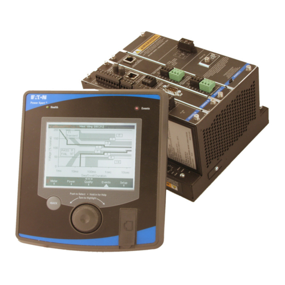
- Page 1 Instruction Leaflet IB02601007E Effective January 2012 Power Xpert® Meter 4000/6000/8000 Quick Start Guide www.eaton.com...
- Page 2 EATON. THE CONTENTS OF THIS DOCUMENT SHALL NOT BECOME PART OF OR MODIFY ANY CONTRACT BETWEEN THE PARTIES. In no event will Eaton be responsible to the purchaser or user in contract, in tort (including negligence), strict liability or otherwise for any special,...
-
Page 3: Table Of Contents
Table of Contents 1 Introduction ................5 Safety Precautions ..............5 2 Quick Start Guide for the Meter Module ....... 7 Safety Precautions ..............7 VT , VX & CT Connections ............10 Establishing Communications between the Meter Module and the Optional Graphic Display Module ....11 Operating the Display Module .......... -
Page 5: Introduction
FAILURE TO GROUND THE POWER XPERT METER MAY RESULT IN INJURY, DEATH ® OR EQUIPMENT DAMAGE. Properly ground the Power Xpert Meter during installation. ® www.eaton.com IB02601007E Page 5... - Page 6 1 Introduction Page 6 IB02601007E www.eaton.com...
-
Page 7: Quick Start Guide For The Meter Module
Improper wiring could cause death, injury and/or equipment damage. Only qualified personnel are to service the Power Xpert Meter 4000/6000/8000 and Graphic Display. TROUBLESHOOTING PROCEDURES MAY REQUIRE PROXIMITY TO EXPOSED ENERGIZED (LIVE) ELECTRICAL WIRING AND/OR PARTS WHERE THE HAZARD OF FATAL ELECTRIC SHOCK IS PRESENT. - Page 8 The Red Status LED will blink if unacknowledged or uncleared events exist. PXMPS-1 Card Power Supply Connection PS1-3 PS1-2 PS1-1 Power Health & Status LEDs Protective Earth Ground Figure 1: Meter Module Power Supply Connection & LED Locations Page 8 IB02601007E www.eaton.com...
- Page 9 • 3-Phase, 3-Wire Delta (Above Up to 600 V L-L, 347 L-N) 2 CTs • 3-phase,4-Wire Y (Up to Up to 600 V L-L, 347 L-N) • 3-phase,4-Wire Y (Above Up to 600 V L-L, 347 L-N) See Installation, for wiring diagrams. www.eaton.com IB02601007E Page 9...
-
Page 10: Vt , Vx & Ct Connections
• Line 2 CT connected to Terminals 21 (polarity mark) & 22 (return) • Line 3 CT connected to Terminals 31 (polarity mark) & 32 (return) • Neutral CT connected to Terminals 41 (polarity mark)& 42 (return) • Ground CT connected to Terminals 51 (polarity mark)& 52 (return) Page 10 IB02601007E www.eaton.com... -
Page 11: Establishing Communications Between The Meter Module And The Optional Graphic Display Module
Module to supply power (24V) to the Display Module. See table below for wiring. Display PXCM Description Terminal Cable Terminal DG2-1 OSCS CM6-1 DG2-2 CM6-2 DG2-3 CM6-3 DG2-4 To local panel ground OSCS=Optional Separate Cable Shield (OSCS used for separate power and data cables) www.eaton.com IB02601007E Page 11... - Page 12 Meter Module’s COM 0 together following basic RS485 wiring specifications. Each Meter Module will need to be uniquely addressed using the Rotary Switch. Rotary Switch CM5-COM 0 CM6 24V Source Figure 5: Meter Module Connections to Display Page 12 IB02601007E www.eaton.com...
-
Page 13: Operating The Display Module
Display Health LED - If Display Module is powered-up, the LED will blink slowly (1/sec). Power Xpert Health Events Health Meter Event Push to Select Hold in for Help Turn to Highlight BACK Back Button Navigation Dial Figure 6: Display Module Controls www.eaton.com IB02601007E Page 13... -
Page 14: Programming The Meter Module Using The Embedded Web Server Interface
For PXCM Cards, the local configuation port may require the use of a UTP Cat 5 cross over cable. The PXMCM card accepts a standard Cat 5 patch cable. Link LED TXRX LED Figure 7: Connect Laptop to Meter Module Page 14 IB02601007E www.eaton.com... -
Page 15: Programming The Meter Module Via The Optional Communications Expansion Card
B. Power cycle the meter to initiate DHCP. If DHCP is not used, an IP address will need to be assigned. CE 1 CE Card CE 2 CE 3 CE 4 Figure 8: Ethernet & Modbus Connections www.eaton.com IB02601007E Page 15... - Page 16 4. Type the Name and Password. The defaults are: Name = admin and Password = admin. After entering the Name and Password, click OK. Note: Without logging into the meter, data is read-only. 5. From the setup menu, click Quick Setup to display basic configuration setup. Page 16 IB02601007E www.eaton.com...
- Page 17 Modbus RTU slave to a master monitoring system. The port defaults as a Master Gateway, which relays Ethernet Modbus TCP command to slave meters connected to the same RS485 link. The Modbus slave address may be set via the display module or with a web browser. www.eaton.com IB02601007E Page 17...
- Page 18 2 Quick Start Guide for the Meter Module Page 18 IB02601007E www.eaton.com...
-
Page 19: Mounting And Wiring
URE TO DO SO CAN RESULT IN INJURY TO PERSONNEL OR DAMAGE TO EQUIP- MENT. The Power Xpert Meter 4000/6000/8000 is designed to be installed, operated and main- tained by adequately trained personnel. These instructions do not include all details, varia- tions or combinations of the equipment, its storage, delivery, installation, checkout, safe operation or maintenance. - Page 20 • The Display Module comes standard with the required hardware, five #8-32 x .50 LG Phillips Pan Int SEMS Screws, for mounting the unit to a door or panel. Panel Cutout Dimensions for Display Module [in/(mm)] Page 20 IB02601007E www.eaton.com...
- Page 21 Status TA: 2.5 CA: 0.2 Reset S1 LED Customer Satisfaction for technical support Freq: 25-66, 350-450 Hz Health www.eaton.com/electrical Oper Temp: -20 TO 60°C <http://www.eaton.com/pxm 1-800-809-2772 or 1-414-449-7100 U.S. Patents #5890097, #6906655, #6975951, #7050913 10VA Source MAX #7054769 PXMIO-B PXMCE-B...
-
Page 22: Wiring
Shorting blocks for CTs and a three-phase switch or cir- cuit breaker for voltage are recommended near the equipment for ease of installa- tion. If assistance with the selection process is desired, contact Power Quality Technical Support representative. Wiring Diagrams Page 22 IB02601007E www.eaton.com... - Page 23 3 Mounting and Wiring www.eaton.com IB02601007E Page 23...
-
Page 24: Fuses
External fuses should be installed in the potential transformer lines as specified in the National Electric Code for the specific application. The power supply wiring should be fused or put on a breaker sized to protect the wire. Page 24 IB02601007E www.eaton.com... -
Page 25: Hipot And Megohm (Megger) Testing
24v source and communication terminals. RS485 fail safe biasing resistors are used at each master port. Eaton strongly recommends using ferrules when connecting to a terminal block. When connecting to a terminal block, the twisted pair sensitivity is critical for COM0, COM1 and COM2. -
Page 26: Rs485 Cable Characteristics
Phoenix Contact and many other vendors carry ferrules and crimping tools for this pur- pose. For more information about RS485 wiring, please refer to TD 17513, Eaton Electrical field Devices Communication Wiring Specification. METER AND DISPLAY MODULE ENVIRONMENTAL RATINGS Display Module Face –... - Page 27 DG1 COM0 RS485 communication port to meters, 2K’ max length • DG11 Data A (-) • DG12 Data B (+) • DG13 Shield (RS485 common) DG2 Display input power 24VDC +/-10%, 6W max draw. • DG21 Shield www.eaton.com IB02601007E Page 27...
- Page 28 If the meter or display modules require cleaning the power and metering inputs should be turned off through their disconnects. The meter and display should be cleaned with a dry clean cloth only, no water or solvents should be used Page 28 IB02601007E www.eaton.com...
-
Page 29: Display Unit Mounting Template
3.15. Display Unit Mounting Template 7.32 [185.9] 3.66 [93.0] 3.00 3.00 [76.2] [76.2] inches [mm] 7.32 [185.9] 7.76 [197.1] R0.06 [R1.5] 0.22 2.00 Ø0.19 [5.6] [50.8] [Ø4.8] 4.00 [101.6]... - Page 30 Power Xpert Meter 4000/6000/8000 Quick Start Guide Eaton Corporation 1000 Cherrington Parkway Moon Township, PA 15108-4312 www.eaton.com For additional information please call: Power Quality Technical Support 1-800-809-2772 option 4 Eaton Corporation Electrical Sector 1111 Superior Ave. Cleveland, OH 44114 United States 877-ETN-CARE (877-386-2273) Eaton.com...
Need help?
Do you have a question about the Power Xpert Meter 4000 and is the answer not in the manual?
Questions and answers