Sign In
Upload
Download
Table of Contents
Contents
Add to my manuals
Delete from my manuals
Share
URL of this page:
HTML Link:
Bookmark this page
Add
Manual will be automatically added to "My Manuals"
Print this page
×
Bookmark added
×
Added to my manuals
Manuals
Brands
Safeline Manuals
Telephone
SL6
Manual
Safeline SL6 Manual
Hide thumbs
1
2
Table Of Contents
3
4
5
6
7
8
9
10
11
12
13
14
15
16
17
18
19
20
21
22
23
24
25
26
27
28
29
30
31
32
33
34
35
36
37
38
39
40
41
42
43
44
45
46
47
48
page
of
48
Go
/
48
Contents
Table of Contents
Troubleshooting
Bookmarks
Table of Contents
Table of Contents
General Information
Overview
Description of the Bus System
System Overview
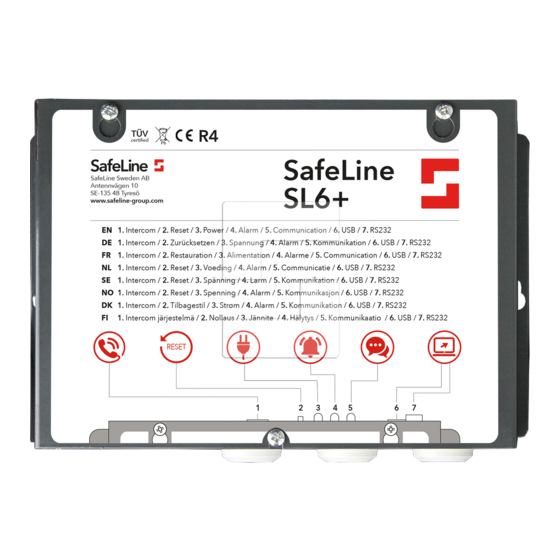
Overview SL6+ Main Unit
Overview SL6+ Voice Station
Address Selection
Installation
Mounting
Wiring Diagram SL6+ Main Unit
Wiring Diagram Voice Station
Wiring Diagram Voice Station Screw Terminals
Connecting the Telephone Line
Activating the SIM Card
Bluetooth LED Indication
LED Indication Front Panel
LED Indication for Pictogram in Car
Startup
Startup Procedure
Configuration
Configuration Overviews
Remote Configuration With Telephone: Step
Initiate a Restart from Remote
On-Site Configuration with Telephone
Configuration Examples
Parameter List
Relay Functions
Operating
Collective Fault
Calling with Safeline SL6
Intercom between Main Unit and Voice Station
Outgoing Call
Emergency Calling Process
Fallback
Fallback LMS Codes
Fire Mode
Service
Battery Function
Trouble Shooting Main Unit
Trouble Shooting Voice Station
Related Test Procedures
Internal Operational Failures
Declaration of Conformity
Advertisement
Quick Links
1
Table of Contents
2
General Information
3
Overview Sl6+ Voice Station
4
Installation
5
Wiring Diagram Voice Station
Download this manual
SL6+ manual
Lift Emergency Telephone
www.safeline-group.com
04.2022
SafeLine SL6+ v.3.9.0 EN
Complies to EN81–28 and EN81–70 standards.
PATENT 08163634.2
© 2022 SafeLine and all the SafeLine products and
accessories are copyrighted by law.
Table of
Contents
Previous
Page
Next
Page
1
2
3
4
5
Advertisement
Table of Contents
Troubleshooting
Trouble shooting main unit
42
Trouble shooting voice station
44
Need help?
Do you have a question about the SL6 and is the answer not in the manual?
Ask a question
Questions and answers
Related Manuals for Safeline SL6
Telephone safeline SL6+ Manual
Emergency lift telephones (44 pages)
Telephone Safeline SL6+ Quick Manual
(86 pages)
Telephone Safeline SL1 Installation Manual
Emergency telephone for lifts (20 pages)
Telephone Safeline SLB-COP Manual
(48 pages)
Telephone Safeline MX3+ Manual
Lift emergency telephone (24 pages)
Telephone SafeLine TTR Installation Manual
Emergency telephone for lifts (32 pages)
Telephone Safeline 1000 Manual
(16 pages)
This manual is also suitable for:
Sl6-4g
Sl6-gsm
Sl6-gsm-board
Sl6-mainboard
Sl6-mini
Sl6-mini-4g
...
Show all
Sl6-mini-gsm
Sl6 a+
Sl6 a+ mini
Sl6 a+ 3g
If-board-4g
Sl6-gsmr
Sl6-mini-gsmr
Slb3-cop
Slb3-rec-pic
Slb3-rec-pic-b
Slb3-sm-pic
Slb3-sm-pic-b
Slb3-sm-pic-l
Slb3-smd-pic
Slb3-smd-pic-b
Slb3-rec-bl
Slb-cop
Slb-cop2
Slb-cop2-l
Slb-cop-l
Slb-cop-sep
Slb-if1
Slb-if2
Slb-rd
Slb-rd-but
Slb-rd-bl
Slb-rd-bel
Slb-rec
Slb-rec-fire
Slb-rec-fire02
Slb-rec-firek
Slb-rec-firek02
Slb-rec-led
Slb-rec-pic
Slb-rec-pic-but
Slb-sm
Slb-sm-led
Slb-sm-pic
Slb-sm-pic-but
Slb-sm-pic-ligh
Slb-smd-pic-but
Slbr-cop
Slbr-sm-pic
Slbr-sm-pic-b
Slbr-rec-pic
Slbr-rec-pic-b
Slbr-rec-pic-b2
Slbr-rec-pic3
Slbr-rd-b-l
Table of Contents
Save PDF
Print
Rename the bookmark
Delete bookmark?
Delete from my manuals?
Login
Sign In
OR
Sign in with Facebook
Sign in with Google
Upload manual
Upload from disk
Upload from URL


Need help?
Do you have a question about the SL6 and is the answer not in the manual?
Questions and answers