Table of Contents
Troubleshooting

Related Manuals for Safeline SL6+


Summary of Contents for Safeline SL6+
- Page 1 SL6 + Manual Lift Emergency Telephone Complies to EN81–28 and EN81–70 standards. www.safeline-group.com PATENT 08163634.2 © 2019 SafeLine and all the SafeLine products and 01.2019 SL6+ v.3.30 EN accessories are copyrighted by law.
-
Page 2: Table Of Contents
LED indication front panel LED indication for pictogram in car Startup procedure Configuration Configure with Safeline CONNECT Parameters unique for SafeLine CONNECT Configuration with PC Configuration with telephone Remote configuration with telephone: Step 1 Remote configuration with telephone: Step 2... -
Page 3: Introduction
SafeLine SL6+ Technical data main unit Power Supply voltage: 230 VAC, 50 Hz, min: 6,4 W, max: 9,4 W Battery Battery voltage: 12 VDC lead battery Capacity: 1,2 Ah Charge: 13,65 VDC, max. 200 mA Emergency light Emergency light output: 12 VDC max 500 mA... -
Page 4: General Information
- This quality product is dedicated for the lift industry. It has been designed and manufactured to be used for its specifi ed purpose only. If it is to be used for any other purpose, SafeLine must be contacted in advance. -
Page 5: Overview
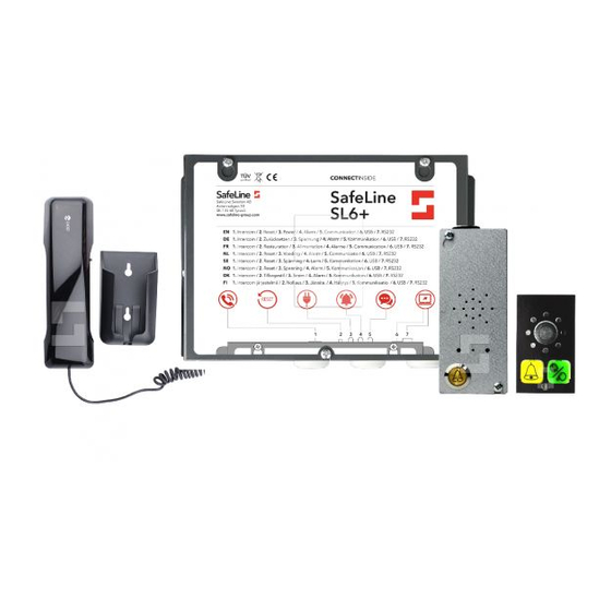
Description of The SL6+ system consists of a main unit and up to six connected voice stations. The system is based on a two-way system according to the bus system EN 81-28 and uses a bus system for communication between main unit and stations. -
Page 6: Overview Sl6+ Main Unit
Overview SL6+ RJ12 connector for optional Screw terminal for optional telephone handset telephone handset main unit For configuration and For configuration and intercom communication. intercom communication. Can also be used for external Can also be used for external calls. Any standard analogue calls. -
Page 7: Installation
Pictogram green ADDRESS Default address setting: Address Unit Car unit Top unit Lift pit unit Fire unit Change the default address settings using SafeLine Pro Fire unit or SafeLine CONNECT. Fire unit Installation SL6+ v.3.30 EN... - Page 8 Overview SL6+ Address selector Fixed value set to 1 (car unit). voice station Connections Pictogram output Additional alarm button, N/O RS232 PC connection Volume control Emergency light, only for SLB-SM-Pic-Light Hearing loop ADDRESS: 1 VOLUME Installation SL6+ v.3.30 EN...
-
Page 9: Mounting
GSM antenna at least 1,5 meters apart. The antenna must be placed on a metallic (earthed) surface of at least 150x150 mm and be placed standing (vertical). SafeLine >> 1.5 m >> 1.5 m >> 1.5 m... -
Page 10: Wiring Diagram Sl6+ Main Unit
Connect the protective earth connection to the enclosure, with a CLEAR/MAINTENANCE cable of at least 1,5mm². * Input 1 and 2 are configurable N/O or N/C inputs with SafeLine Pro FIRE MODE (default input 2) or CONNECT. For configuration details, se tabel to the left. -
Page 11: Wiring Diagram Voice Station
B4 bus B RJ45 / JST JST connection *Cable18 *Input A is configured with either: • SafeLine Pro or CONNECT, N/O (default) or N/C. • Parameter *89*, please refer to the corresponding code in the ”Parameter List”. Installation SL6+ v.3.30 EN... -
Page 12: Wiring Diagram Voice Station Screw Terminals
Wiring diagram *Input A is configured with either: • SafeLine Pro N/O (default) or N/C. voice station • Parameter *89*, please refer to the corresponding screw terminals code in the ”Parameter List”. 1. Bus A 2. Bus B 3. Output A, yellow pictogram 4. -
Page 13: Activating The Sim Card
If the PIN is set to “1111”, the code will be randomly generated by the SafeLine GSM unit and memorized. This is a safety measure, making sure the SIM card will only work with the selected SafeLine GSM unit. To change the PIN again, use the PUK code provided to you by your mobile services provider for setting up a new PIN. -
Page 14: Startup
LED indication front panel LED 1 indicates the power supply status Continuous green Mains power supply OK Flashing red (400/400 ms) Battery operated, with power to the emergency light. Continuous red Battery operated, no power to the emergency light. LED 2 indicates active alarm and battery condition Light off No active alarm/battery OK. -
Page 15: Led Indication For Pictogram In Car
Call connected The yellow pictogram LED is lit The green pictogram LED turns as soon as the alarm button is on as soon as the SafeLine unit pressed. detects a responding voice. The LED is turned off when the call is terminated. -
Page 16: Startup Procedure
Startup procedure Startup the SL6+ Connect the battery NOTE: The unit will not start at battery connection only. Upon startup: a tone se- quence is heard in the system speaker Connect 230 VAC Check 230 VAC mains power. SL6+ main unit searches for stations connected to the bus. -
Page 17: Configuration
Configure Download SafeLine CONNECT from Google Play or the Apple App Store. To fully use the app’s features you must register an account. with Safeline In the upper corner you can access a menu containing account information, patch notes and a demo mode. To register an account: CONNECT select account and then ”Register new account”. -
Page 18: Parameters Unique For Safeline Connect
“Battery test active” function Main unit diagnostics -> Battery test active • Test function shown in the SafeLine CONNECT app, to view if a battery test is in progress. Emergency light car Top/Pit Configuration -> Voice stations -> Emergency light car top/pit •... -
Page 19: Configuration With Pc
SafeLine SafeLine Remote configuration with SafeLine Pro/ProLink The unit can also be remotely configured at the office after installation. Connect a SafeLine ProLink modem with a phone line to a computer with SafeLine Pro and a serial cable. SafeLine SafeLinePro... -
Page 20: Configuration With Telephone
"On-site configuration with telephone". 1 2 3 4 5 6 SafeLine 7 8 9 SafeLine Remote configuration with telephone For remote configuration, you can use any PSTN tone dial phone. • Dial the phone number of the SL6+. - Page 21 Choose which unit to Press unit number [1-9]. configure by pressing the unit's number. Note: If there are other SafeLine telephones connected in serial you may have to press the unit number several times before the 3 long tones are heard.
-
Page 22: Remote Configuration With Telephone: Step
Remote After having entered voice communication mode, use the parameter codes found in the "Parameter List" to remotley configure the SL6+. configuration with telephone: step 2 Note: If the time between the Remote configuration, operation of two keys exceeds external telephone 10 seconds, the code has to be re-entered. -
Page 23: On-Site Configuration With Telephone
On-site configuration with telephone On-site configuration with telephone Pick up the telephone and wait for dial tone Dial to enter configuration mode 2 short beeps (entering config. mode) Quit configuration Continue configure? Enter prefix, eg: *11*012341234# 2 short beeps Enter setting, eg: *11*012341234# End parameter: *11*012341234# Call disconnected... -
Page 24: Configuration Examples
Alarm button delay: - Example: 3 seconds delay. End configuration: Example 2. SLCC (SafeLine Call Centre) and 3 day test. Start configuration: Enter P100 ID code Lift ID code (each lift must have its own unique code). Set test alarm type: - Example: Test alarm type P100. -
Page 25: Parameter List
Parameter list CONFIGURATION DATA CODE DATA COMMENTS Enter configuration mode Enter password * - - - - # Default = 0000 Exit configuration mode *00*# ALARM CODES CODE DATA COMMENTS P100 ID code *01* - - - - - - - - # P100 is always 8 digits CPC ID code *02*... - Page 26 TEST ALARM & CODE DATA COMMENTS BATTERY ALARM LMS phone number *16* - - - - - - - - - # LMS (Lift Monitoring System) phone number to alarm receiver or SLCC. Test alarm *17* - - - - - - - - - # Phone number to send testalarm to alarm receiver or SLCC.
- Page 27 DISTRESS MESSAGE CODE DATA COMMENTS Record distress message played in *50* ”Speak” # This message will be played in the lift car when the emergency lift telephone starts the lift car. calling the alarm centre, so make sure it's quiet when recording the message. Example of message: "Please do not panic, the emergency telephone is now calling the emergency...
- Page 28 OTHER CODES CODE DATA COMMENTS 2G/3G/4G *07* Selects which network combination to be available when * IF-BOARD-4G is installed 0 = 2G + 3G + 4G (default) 1 = 2G + 3G 2 = 2G + 4G 3 = 3G + 4G 4 = 2G 5 = 3G 6 = 4G...
- Page 29 When the unit number is assigned, the specified unit is accessible for configuration. Detect dial tone *83* 0 = Off 1 = On (default) Set to off if SafeLine has problem to detect the dial tone. Configuration SL6+ v.3.30 EN...
- Page 30 OTHER CODES CODE DATA COMMENTS Receipt to alarm receiver *84* - # Select which message(s) to send to the alarm receiver at an alarm call. 0 = None (default) 1 = Start of alarm 2 = Start+end of alarm Break on new alarm *86* Disconnects a call longer than 60 sec.
- Page 31 OTHER CODES CODE DATA COMMENTS Voice station *90* - - # Local configuration of emergency bell voice station. - Integrated emergency bell First number selects voice station (1-6). Second number selects Off (0 = default) or On (1). Example: *90*21# sets voice station 2 to On Pwd for remote configuration *91* - - - - # Change password (default=0000).
-
Page 32: Relay Functions
Relay functions Alarm status outputs • Relay will be activated when set time is reached. • Relay will be deactivated when emergency This applies for SW 4.00 or later. call ends. (For functions of earlier versions, please contact the Support team.) Battery failure Relays 1 and 2 can be •... -
Page 33: Operating
When function is active it is relay function affected by 3 failures: Activate this relay function in 1. Battery failure the SafeLine CONNECT app or • Deactivates in case of failed battery test SafeLine Pro. • Resets by pressing the “Reset Button”... -
Page 34: Calling With Safeline Sl6
(Hold the button for 5 seconds to make an emergency call.) Outgoing call Press 0 to dial external telephone number. If the Safeline SL6+ is con- nected to a PABX (switchboard), press 0 again for external dial tone to calling out to the PSTN network. If a GSM board is installed, the SL6+ will use it as the default . -
Page 35: Emergency Calling Process
Emergency Push the alarm button in the lift cabin to initiate an emergency call. To restart the dialling process, push the alarm button again. calling process With 4 stored telephone Emergency numbers in the system, each call number can be called 3 times. This adds up to the 12 call limit. -
Page 36: Fallback
GSM SIM card are active). parameter *93* (please refer to the corresponding code in the Enable Fallback through SafeLine CONNECT or SafeLine Pro. When ”Parameter List”). activating Fallback, both systems have to be operative. Incoming calls are handled by both interfaces, but will not be used simultaneously. -
Page 37: Fallback Lms Codes
Fallback LMS Fallback LMS codes: codes Z001: PSTN: If mains power is out longer than set time (Fallback Alarm Delay), an LMS is sent with the code Z001. Z002: When power returns and has been back for more than set time, an LMS is sent with the code Z002. -
Page 38: Fire Mode
"Wiring diagram SL6+ main unit" (page 10). Configuration Use SafeLine Pro, CONNECT or parameter *73* (please refer to the corre- sponding code in the ”Parameter List”) to configure the units for Fire mode. • Set Input 1 to Fire mode: *73*14#. -
Page 39: Service
Battery function The expected life of a lead battery is approximately 3 years, but several factors can affect the battery’s life time, for example: • Ambient temperature • Humidity, • Long-time storage of the battery before powering, etc. • If the battery has been completely discharged for a longer period of time, it will never regain full capacity. -
Page 40: Troubleshooting Main Unit
PROBLEM POSSIBLE CAUSE(S) SOLUTION The unit makes an alarm call • Improper type of alarm Use SafeLine Pro or a telephone and when powered up. button selected. parameter *74* and/or *89* to change • Alarm button is stuck. from N/C (Normally closed) to N/O (Normally open) or from N/O to N/C. -
Page 41: Troubleshooting Voice Station
Troubleshooting voice station PROBLEM POSSIBLE CAUSE(S) SOLUTION The unit can not make an alarm call. • At least one phone number • Check wiring. and/or one ID code if using • At least one voice station must data identification must be be connected in order to make programmed to make a call an alarm call. -
Page 42: Related Test Procedures
Related test * Telephone line check 1. Power up the unit. Procedures 2. Lift the configuration handset. 3. Wait for dial tone. 4. Dial “0”. 5. Wait for new dial tone. 6. Call another telephone and start a normal conversation. 7. -
Page 43: Declaration Of Conformity
Rev. 03.016 / Rev. 03.017 / Rev. 03.019 / Rev. 03.025 GL865-Dual V3: 16.00.152 / 16.01.150 / 16.01.153 LE910-EU V2: 20.00.402 SafeLine SL6 4.45 Tyresö, 2017-04-07 Lars Gustafsson, Technical Manager, R&D , SafeLine Group Antennvägen 10, 13548 Tyresö, Sweden +46 (0)8-447 79 32, www.safeline-group.com... - Page 44 Support: +32 (0)4 85 89 08 95 SafeLine Deutschland GmbH Kurzgewannstraße 3 · D-68526 Ladenburg · Germany Tel.: +49 (0) 6203 - 840 60 03 · sld@safeline.eu SafeLine Group UK Unit 47 · Acorn Industrial Park · Crayford · Kent · DA1 4AL · United Kingdom info@safeline-group.uk...
Need help?
Do you have a question about the SL6+ and is the answer not in the manual?
Questions and answers