Table of Contents
Advertisement
Quick Links
See also:
Quick Manual
Advertisement
Table of Contents

Related Manuals for Safeline MX3+


Summary of Contents for Safeline MX3+
- Page 1 MX3+ Manual Lift Emergency Telephone Reliability – brought to you from Tyresö Sweden www.safeline-group.com © 2018 SafeLine and all the SafeLine products and 12.2018 MX3+ v.2.02 EN accessories are copyrighted by law.
-
Page 2: Table Of Contents
Content Introduction Technical data General information Overview Overview MX3+ Parallel wiring Wiring diagram H1/H2 Wiring diagram output 1, 2 and external button Outputs Configuration CONNECT Configuration interfaces Configuration methods Configuration examples Parameter list Operating LED indication Testing Emergency calling progress Troubleshooting Certificate Declaration of conformity... -
Page 3: Introduction
SafeLine MX3+ Technical data Power: 10 - 30 VDC Consumption: In standby: 50 mA at 12 VDC Operation: 160 mA at 12 VDC Input: 10 to 30 VDC, 5 mA optically isolated Output: 2x 12 to 24 VDC, max 200 mA (transistor negative) -
Page 4: General Information
- This quality product is dedicated for the lift industry. It has been designed and manufactured to be used for its specifi ed purpose only. If it is to be used for any other purpose, SafeLine must be contacted in advance. -
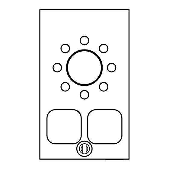
Page 5: Overview
Volume control To increase volume, press Button ”2”; to decrease volume, press Button ”8”. It is also possible to adjust the volume in the SafeLine CONNECT app (available on both Google Play and Apple App Store). Output for additional voice station/hearing loop When connecting an additional remote station Cable14 is required. - Page 6 Wiring diagram, H1/H2 Use CABLE15 to connect SafeLine MX3+ with a hearing loop. Hearing loop serial no. hologram sw ver. 1 2 3 www.safeline-group.com 4 5 6 Speaker B * 0 # Speaker A SafeLine MX3+ CABLE15 Overview MX3+ v.2.02 EN...
-
Page 7: Wiring Diagram Output 1, 2 And External Button
The two outputs can be configured independently with a number of functions. The configuration serial nr. is performed via SafeLine Pro or with the hologram configuration code *88*XY#, where X specifies output 1 or 2 and Y specifies the function: sw ver. -
Page 8: Outputs
The function will automatically disconnect a call if no sound is received from the alarm operator within a set time. Only works for voice calls, not for P100/CPC/Q23. The configuration is performed via SafeLine Pro or with the configuration code *92*X#, where X specifies the time: The function is off. -
Page 9: Configuration
Configure Download SafeLine CONNECT from Google Play or the Apple App Store. To fully use the app’s features you must register an account. with Safeline In the upper corner you can access a menu containing account information, patch notes and a demo mode. To register an account: CONNECT select account and then ”Register new account”. -
Page 10: Configuration Interfaces
For remote configuration, you can use any PSTN tone dial phone. Please find the instructions of how to perform it in the section ”Configuration method” (page 12). Remote configuraion with SafeLine Pro Connect an SLPro Link to a computer with SafeLine Pro and a serial cable. SafeLine SafeLinePro SafeLine... - Page 11 Configuration Remote configuration On-site configuration with external telephone. with telephone using the keyboard. Dial phone number. If the time between the operation of two keys exceeds 10 seconds, the code has Multiple units to be re-entered. If the time connected to exceeds 30 seconds, the call is phone line? disconnected or configuration...
-
Page 12: Configuration Examples
5.Call type 2 number: 6.Alarm button delay: - Example: 3 seconds delay. 7.End configuration: Example 2: SLCC (SafeLine Call Centre) and 3-day test. 1.Start configuration: 2.Enter P100 ID code: Lift ID code (each lift must have its own unique code). -
Page 13: Parameter List
Parameter list CONFIGURATION CODE DATA COMMENTS Enter configuration mode Enter password * - - - - # Default = 0000 Exit configuration mode *00*# ALARM CODE DATA COMMENTS P100 ID code *01* - - - - - - - - # P100 is always 8 digits CPC ID code *02*... - Page 14 TEST ALARM CODE DATA COMMENTS BATTERY ALARM LMS phone number *16* - - - - - - - - - # LMS (Lift Monitoring System) phone number to alarm receiver or SLCC. Test alarm *17* - - - - - - - - - # Phone number to test alarm receiver or SLCC. Days between tests *27* - - #...
- Page 15 OTHER CODES CODE DATA COMMENTS Emergency signal in *71* The speaker siren will sound at emergency speaker call. 0 = Off (default) 1 = On Ring-tone timeout *72* - - # Number of ring signals before dialling the next number (default = 08). Additional input *73* Selects input function:...
- Page 16 0 = Off automatically 1 = On (default) Auto answer *81* - - # Number of signals before SafeLine answers incoming call. Can be set from 00-16 (default = 02). 00 = Never answering. Unit number *82* Unit number [0] is set by default, and means that the unit will respond immediately.
- Page 17 DATA COMMENTS Detect dial tone *83* 0 = Off 1 = On (default) Set to off if SafeLine has problem to detect the dial tone. Receipt to alarm *84* Select which message(s) to send to the alarm receiver with P100 receiver at an alarm call.
- Page 18 OTHER CODES CODE DATA COMMENTS Microphone sensitivity *90* The sensitivity of the microphone can be reduced in three levels. 0 = No reduction (default) 1 = 20 % Reduction 2 = 40 % Reduction 3 = 60 % Reduction Change password *91* - - - - # Change password (default=0000).
-
Page 19: Operating
Call connected The yellow pictogram LED is lit The green pictogram LED turns as soon as the alarm button is on as soon as the SafeLine unit pressed. detects a responding voice. The LED is turned off when the call is terminated. -
Page 20: Testing
Testing Testing the SafeLine MX3+ Connect 10-30 VDC. SafeLine MX3+ will make a self-test. Green LED flashes Yellow LED flashes 5 times. 5 times. Short tone Long tone in the speaker. in the speaker? Check the mic and speaker Connect telephone line. -
Page 21: Emergency Calling Progress
Emergency Emergency alarm calling process activated. Wait 1 minute. Maximum 12 calls: with 4 stored telephone numbers, each number could Receiving tone? Line missing or busy. be called 3 times. This adds up to the 12 call limit. To restart the dialling process, another push of the alarm button is needed. -
Page 22: Troubleshooting
Troubleshooting The telephone beeps every 5 seconds This is to notify the passengers of the ongoing call (anti eaves dropping). The unit makes an alarm call when powered up Emergency Emergency • Improper type of emergency button selected. Change from button N/O button N/C N/C to N/O or from N/O to N/C. -
Page 23: Declaration Of Conformity
0214.26 R 104750/51 EN 300 328 V2.1.1 3.2: Effective use of spectrum allocated Firmware used during assessment SafeLine MX3: 1.00 Tyresö, 2017-04-07 Lars Gustafsson, Technical Manager, R&D , SafeLine Group Antennvägen 10, 13548 Tyresö, Sweden +46 (0)8-447 79 32, www.safeline-group.com... - Page 24 Support: +32 (0)4 85 89 08 95 SafeLine Deutschland GmbH Kurzgewannstraße 3 · D-68526 Ladenburg · Germany Tel.: +49 (0) 6203 - 840 60 03 · sld@safeline.eu SafeLine Group UK Unit 47 · Acorn Industrial Park · Crayford · Kent · DA1 4AL · United Kingdom info@safeline-group.uk...
Need help?
Do you have a question about the MX3+ and is the answer not in the manual?
Questions and answers