Table of Contents
Advertisement
Quick Links
Advertisement
Table of Contents

Related Manuals for Campbell TEMP 120


Summary of Contents for Campbell TEMP 120
- Page 1 Revision: 01/2022 Copyright © 2019 – 2022 Campbell Scientific CSL I.D - 1318...
- Page 2 Quotations for repairs can be given on request. It is the policy of Campbell Scientific to protect the health of its employees and provide a safe working environment, in support of this policy a “Declaration of Hazardous Material and Decontamination”...
- Page 3 About this manual Please note that this manual was originally produced by Campbell Scientific Inc. primarily for the North American market. Some spellings, weights and measures may reflect this origin. Some useful conversion factors: Area: 1 in (square inch) = 645 mm Mass: 1 oz.
- Page 4 • Periodically (at least yearly) check electrical ground connections. WHILE EVERY ATTEMPT IS MADE TO EMBODY THE HIGHEST DEGREE OF SAFETY IN ALL CAMPBELL SCIENTIFIC PRODUCTS, THE CUSTOMER ASSUMES ALL RISK FROM ANY INJURY RESULTING FROM IMPROPER INSTALLATION, USE, OR MAINTENANCE OF TRIPODS, TOWERS, OR ATTACHMENTS TO TRIPODS AND TOWERS...
-
Page 5: Table Of Contents
8.2.4 Compliance 8.2.5 Physical attributes 9. Installation 9.1 Install driver for computer connection 9.2 Operating systems 9.3 Configuring TEMP 120 9.3.1 Configuring with SURVEYOR 9.3.2 Configuring with the CPIAddModule() instruction 9.3.3 Configuring with Device Configuration Utility 9.3.4 Configuring with CPIStatus table 9.4 Data logger programming... - Page 6 9.4.1 Scan buffers 9.4.2 GRANITE Measurement Module instructions 9.5 Data logger connection 9.6 Connecting multiple GRANITE Measurement Modules 9.6.1 Daisy-chain topology 9.6.2 Star topology 9.7 Power connection 9.7.1 Power-up sequence 9.8 Earth ground connection 9.9 Mounting in an enclosure 10. Operation 10.1 SURVEYOR control 10.2 Data logger control 10.3 Measurements...
-
Page 7: Introduction
Check that expected cable lengths were received. Contact Campbell Scientific immediately if you find any discrepancies. Check the operating system version in the TEMP 120, and the data logger. Update as needed. See Operating systems (p. -
Page 8: Measurement Quickstart Using Surveyor
Campbell Scientific SURVEYOR software is an easy way to quickly see measurement results and store data from the TEMP 120. The module configuration can be saved on the computer or exported as a CRBasic data logger program. SURVEYOR is available as a download from www.campbellsci.com/cs-surveyor... - Page 9 9. Add Measurement(s). For this exercise, add a Type-T differential thermocouple on Channel 1. Insert the sensor into Terminal 1 on the TEMP 120. 10. Complete the rest of the form and Apply to save the configuration. TEMP 120...
-
Page 10: Programming Quickstart Using Surveyor
5. Programming quickstart using SURVEYOR Campbell Scientific SURVEYOR is an easy way to generate a simple CRBasic program for your TEMP 120 Campbell Scientific data acquisition system. 1. Configure the TEMP 120 for measurements, see Measurement quickstart using SURVEYOR (p. -
Page 11: Programming Quickstart Using Short Cut
Devices folder. Double click the GRANITE Measurement Module you are working with. Type the serial number located on the TEMP 120 label. Optionally, type a name in the Module ID String if you want the module to have an ID. This is useful when multiple TEMP 120 modules are connected to the data logger. - Page 12 Sensors > Temperature folder. Double click Type T Thermocouple. Type the number of type T thermocouples connected to the TEMP 120. The temperature defaults to degree C. This can be changed by clicking the Temperature units box and selecting one of the other options.
- Page 13 5. Click on the Wiring tab to see how the sensor is to be wired to the TEMP 120. Click OK after wiring the thermocouple. 6. Repeat steps four and five for other sensors you want to measure. Click Next.
-
Page 14: Overview
9. Click Finish and save the program. Send the program just created to the data logger if it is connected to the computer. 10. If the thermocouple is connected to the TEMP 120, check the output of the thermocouple in the data display of LoggerNet, RTDAQ, or PC400 to make sure it is making reasonable measurements. -
Page 15: Wiring Panel Overview
FIGURE 7-2. Power and CPI ports view (left) and ground lug view (right) Earth Ground Lug (⏚) – connection point for a heavy-gauge earth-ground wire. A good earth connection is necessary to secure the ground potential of the TEMP 120 and shunt transients away from electronics. 14 AWG wire, minimum, is recommended. -
Page 16: Communications Ports
7.1.2.2 CPI port When the TEMP 120 has successfully been configured by a data logger, the green LED on the CPI port will flash. For scan rates 500 ms or slower, it will flash at the scan rate. For faster scan rates, the green LED will flash every few scans. -
Page 17: Module
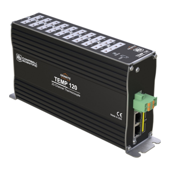
Normal-mode rejection: >80 dB at 50 and 60 Hz 8.2 Module 8.2.1 Communications CPI: RJ45 interface to Campbell Scientific data loggers, sensors, and GRANITE Measurement Modules. USB: USB micro-B device only, 2.0 full-speed 12 Mbps, for computer connection. TEMP 120... -
Page 18: System
After installing a field station, wait long enough to confirm that good measurements are being made, that data is collected by the data logger, and that data from the data logger can be copied to a computer. 9.1 Install driver for computer connection 9.2 Operating systems TEMP 120... -
Page 19: Install Driver For Computer Connection
For best performance, use the most recent OS for each device. 9.3 Configuring TEMP 120 The TEMP 120 arrives ready to be connected to a system. Device configuration is only required when multiple GRANITE Measurement Modules are connected to a single data logger. Each module must have a unique CPI address. -
Page 20: Configuring With Surveyor
SURVEYOR, Device Configuration Utility or the CPIStatus table. 9.3.3 Configuring with Device Configuration Utility Install the device driver before connecting the TEMP 120 to a computer. This is optional for Windows 10, or later, operating systems. 1. Open Device Configuration Utility. -
Page 21: Configuring With Cpistatus Table
9. Click Connect then OK to avoid conflicts. 10. Set the Device Name (optional) and the CPI Address. a. Device Name is a user-editable field to set a unique name to the TEMP 120. The default name is TEMP 120. -
Page 22: Scan Buffers
The data logger processes the data from the TEMP 120 in batches according to frame syncs received from the TEMP 120. Upon receiving a batch of data, the data logger puts it into a processing queue. Processing the data may take more time than is available in a single scan. The BufferOption allows the data logger to balance its task load by processing the data from the TEMP 120 during subsequent scans while maintaining correct data time stamps. -
Page 23: Data Logger Connection
EndProg 9.5 Data logger connection TEMP 120 devices communicate with a data logger through a CPI port. Each TEMP 120 ships with a 6-inch RJ45 cable for this connection, though any CAT5e, or better, RJ45 cable can be used. To allow daisy-chaining, two CPI ports are available on the TEMP 120. -
Page 24: Star Topology
A star topology uses a passive RJ45 hub, such as the HUB-CPI, to connect multiple GRANITE Measurement Modules. An illustration of this is shown in FIGURE 9-2 (p. 18). NOTE: Do not use a CPI terminator with this configuration. FIGURE 9-2. Multiple GRANITE Measurement Modules connected in a star topology TEMP 120... -
Page 25: Power Connection
9.7 Power connection Connect the power supply to the removable Power connector on the side of the TEMP 120. Power supplies providing voltages from 9.6 to 32 VDC may be used. While the input power requirements of Campbell Scientific instruments vary, there is one constant –... - Page 26 FIGURE 9-3. Enclosure backplate mounting If mounting to a DIN rail, use the GRANITE-series DIN-Rail Kit as shown in the following images. FIGURE 9-4. GRANITE DIN-Rail Mounting Kit TEMP 120...
-
Page 27: Operation
When the TEMP 120 receives a sync signal, it begins making measurements. The measurement order on the TEMP 120 follows the sequence of the instructions addressed to it within the current active scan of the data logger program. After the measurements are completed, it sends the data to the data logger for processing. -
Page 28: Cpi Network Bit Rate
(p. 23) for the maximum cable length allowed for the topology and bit rate your network requires. The bit rate of the network defaults to 250 kbps and can be changed by using CPISpeed() instruction in the data logger program. TEMP 120... -
Page 29: Multiple Devices
Designing Physical Network Layouts for the CPI Bus When including two or more TEMP 120 devices in the program, the processing mode of the data logger affects the measurement timing of each TEMP 120. In sequential mode, the TEMP 120 devices make measurements one after the other, following the order of their instructions within the program. -
Page 30: Troubleshooting
4. Verify that each TEMP 120 in the network has a unique CPI address. 5. Check the data logger and TEMP 120 operating system and update them as needed. 6. Check that the scan rate is long enough for the measurement time. The data logger compiler often catches scan rates that are too fast. -
Page 31: Status Led
12.2 Status LED The Status LED indicates the current operation of the TEMP 120, as shown in the following table.. Table 12-2: COMM Status LED Activity Module has been configured by data logger and is receiving sync... -
Page 32: Replacing A Granite Measurement Module
12.4 Replacing a GRANITE Measurement Module An existing TEMP 120 can be replaced with a new module using the same CPI address without requiring a change to the program. TEMP 120... -
Page 33: Appendix A. Importing Short Cut Code Into Crbasic Editor
Block. This adds an apostrophe (') to the beginning of each of the highlighted lines, which instructs the data logger compiler to ignore those lines when compiling. The Comment Block feature is demonstrated at about 5:10 in the CRBasic | Features video TEMP 120... -
Page 34: Appendix B. Example Programs
House", 6) 'Main Scan Scan(5, SEC, 3, 0) '15 TCs on each TEMP 120 w/ CPI addresses 4, 5, and 6 CDM_TCComp(TEMP120, 4, TC_Set1(), 15, 1,TypeT, TRUE, 0) CDM_TCComp(TEMP120, 5, TC_Set2(), 15, 1,TypeT, TRUE, 0) CDM_TCComp(TEMP120, 6, TC_Set3(), 15, 1,TypeT, TRUE, 0) -
Page 35: Measuring Thermocouples
CRBasic Example 3: Measuring thermocouples 'GRANITE 6 Datalogger 'This program sets CPI Address and Device Name on a TEMP 120 with serial 'number 1234 and uses the TEMP 120 to measure 20 Type-T thermocouples. 'Declare Variables and Units... -
Page 36: Measuring Temp 120 And Volt 108 At Different Speeds
The following program measures a full-bridge sensor on a VOLT 108 at 100 Hz in the main sequence, and 20 type-T thermocouples on a TEMP 120 module in a 5-second slow sequence. CRBasic Example 4: Measuring TEMP 120 and VOLT 108... -
Page 37: Synchronized Temp 120 And Volt 108 Measurements
The following program measures a full-bridge sensor on a VOLT 108 at 100 Hz, and 20 type-T thermocouples on a TEMP 120 module at 1 Hz. The measurements are synchronized by putting the faster measurements in a SubScan. CRBasic Example 5: Synchronized TEMP 120 and VOLT 108 measurements... - Page 38 Campbell Scientific Regional Offices Australia France Thailand Location: Garbutt, QLD Australia Location: Vincennes, France Location: Bangkok, Thailand Phone: 61.7.4401.7700 Phone: 0033.0.1.56.45.15.20 Phone: 66.2.719.3399 Email: info@campbellsci.com.au Email: info@campbellsci.fr Email: info@campbellsci.asia Website: www.campbellsci.com.au Website: www.campbellsci.fr Website: www.campbellsci.asia Brazil Germany Location: São Paulo, SP Brazil...
Need help?
Do you have a question about the TEMP 120 and is the answer not in the manual?
Questions and answers