Table of Contents
Advertisement
Advertisement
Table of Contents

Related Manuals for Key-Disp KD51C


Summary of Contents for Key-Disp KD51C
-
Page 2: Table Of Contents
Contents Product Name and Model........................1 Specifications............................1 Appearance and Size..........................1 ◆Display appearance and size....................3 ◆Remote appearance and size....................3 Function summary and layout......................2 ◆Function Summary........................3 ◆Function Layout...........................3 General Operation..........................4 ◆Switching the E-bike System On/Off..................4 ◆Display Interface......................... 4 ◆Switching Push-Assist Mode On/Off.................. - Page 3 ◆Speed Sensor (optional)......................14 ◆Throttle Settings (optional)......................14 Throttle Push-assistance Enable/Disable................14 Throttle Level Enable/Disable....................14 ◆System Settings (optional)...................... 15 Delay Time Settings of Battery Power..................15 Max Speed Limited........................16 Push-assistance button Enable/Disable................16 Slow Start Up Settings......................17 ◆Power-on Password Settings....................17 ◆Power-on Password Enable/Disable..................15 ◆Power-on Password Change....................18 ◆Exit Settings..........................19...
-
Page 4: Product Name And Model
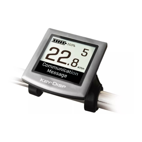
Product Name and Model Intelligent Segment LCD display of E-bike Model: KD51C. Specifications ●Rated voltage: 24V/36V/48V ●Rated working current: 10mA ●Maximum working current: 30mA ●Off-state leakage current: <1uA ●Operating temperature: -20℃~ 60℃ ●Storage temperature: -30℃~ 70℃ Appearance and Size ◆Display appearance and dimensional drawing (unit: mm) - Page 5 ◆Remote appearance and dimensional drawing (unit: mm)
-
Page 6: Function Summary And Layout
Function summary and layout ◆Function summary KD51C has many functions to meet the riders’ needs. The indicating elements are as follows: ●Smart battery indication ●Assist level ●Speed indication (incl. Current speed, max. speed and avg. speed) ●ODO and trip ●The push-assistance function ●Trip time... -
Page 7: General Operation
General Operation ◆Switching the E-bike System On/Off To switch on the E-bike system and provide the power supply to the controller, hold the On/Off button on the remote for 1 second. To switch off the E-bike system, hold the On/Off button for 2s. The E-bike system no longer uses the battery power. -
Page 8: Switching The Lighting On/Off
Push-assistance Mode Push-assistance function may only be used when pushing the E-bike. Be aware of ▉ danger of injury when the wheels of the E-bike do not have ground contact while using the push-assistance function. ◆Switching the Lighting On/Off To switch on E-bike front light or rear light, briefly press the “ ”... -
Page 9: Assist Level Selection
Assist Level “5” ◆Battery Indicator The five battery bars represent the capacity of the battery. Each bar is equivalent to a capacity of approx. 20%. The five battery bars are bright when the battery is in full voltage. When the battery is in low voltage, battery frame will flash to give a notice that the battery needs to be recharged immediately. -
Page 10: Error Code Indication
◆Error Code Indication The components of the E-bike system are continuously and automatically monitored. When an error is detected, the respective error code is indicated in text indication area. Refer to the detail message of the error codes in Attached list 1. Error Code Indication ▉... -
Page 11: Backlight Contrast Settings
◆Backlight Settings bL represents backlight settings. Level “1” is the low brightness, Level “2” is the medium brightness, and Level “3” is high brightness. The default level is “1”. To modify the backlight brightness, press the “+” button or the “-” button to choose the desired setting item. -
Page 12: General Parameter Settings
General Parameter Settings To access General Parameter Settings interface, hold both the “+” and the “-” button for 2s (General Settings page) and then hold both “-” button and remote “i” button for 2s again. ◆Wheel Diameter Settings Ld represents wheel diameter settings. Optional values are 16, 18, 20, 22, 24, 26, 700C and 28. -
Page 13: Personalized Parameter Settings
Personalized Parameter Settings Personalized Parameter Settings can meet a variety of individual requirements. Key- Disp displays work with different protocols, support the settings of different personalized items. There are 8 settings items: Battery Power Bar Settings, Assist Level Settings, Controller Over-current Cut Settings, Power Assist Sensor Settings, Speed Sensor Settings, Throttle Function Settings, System Settings and Power-on Password Settings. -
Page 14: Assist Level Settings (Optional)
◆Assist Level Settings(optional ) ‘SCA’ represents power assist level settings. Assist level Mode Selection In Assist level settings, there are 8 modes : 0-3, 1-3, 0-5, 1-5, 0-7, 1-7, 0-9, 1-9. The default mode is 0-5. To change the mode of Assist level, press the “+” or the “-” button to choose the desired mode and press the “i”... -
Page 15: Controller Over-Current Cut Settings (Optional)
◆Controller Over-current Cut Settings (optional) CUR represents controller over-current cut settings. CUR value can be changed from 7.0A to 25.0A. The default value is 15A. To change basic settings, press the “+” or the “-” button to increase or decrease the value of the current. -
Page 16: Pas Sensitivity Settings
The PAS Sensitivity Settings SCN represents the sensitivity of PAS settings. The sensitivity value is “2” to “9”. “2” is the strongest, “9” is the weakest. The default value is “2”. To change the sensitivity of PAS, press “+” or “-” button to choose sensitivity value. To store a changed setting, press the “i”... -
Page 17: Speed Sensor (Optional)
◆Speed Sensor (optional) SPS represents speed sensor settings. The default value is 1 To change speed sensor settings, press the “+” or the “-” button to select the quantity of magnet head (the range is from 1 to 15). To store a changed setting, hold the “i” button and then return to previous menu. Speed Sensor Setting ◆Throttle Settings (optional) Throttle Push-Assistance Enable/Disable... -
Page 18: System Settings (Optional)
If you choose y, the maximum speed can only be the highest speed powered by current assist level when you twist the throttle. If you choose n, the maximum speed is not limited by current assist level and you can override whatever level you are in and reach rated maximum speed when you twist the throttle. -
Page 19: Max Speed Limited
Max. Speed Limit LS represents max. speed limit settings. The default value is 40Km/h. To change Max speed limit setting, press the “+” or the “-” button to set the max speed from 25Km/h to 40 Km/h. To store a changed setting, press the “i” button and then access push-assistance button enable/disable settings. -
Page 20: Slow Start Up Settings
Slow Start up Settings SSP represents slowly start up. The range is “1-4”, “4” is the slowest. The default value is “1”. To change slowly start up settings, press the “+” or the “-” button to select the desired value. To store a changed setting, press the “i”... -
Page 21: Power-On Password Enable/Disable
◆Power-on Password Enable/Disable To change power-on password enable/disable settings, press “+” or “-” button to choose Y or N. Y means power-on password is enabled. N means power-on password disabled. The default value is N. If you choose Y, press the “i” button and then access power-on password change interface. -
Page 22: Exit Settings
◆Exit Settings In the settings interfaces, Press the “i” button is to confirm the input. Hold down the “i” button is to store the settings, and exit the current settings. Hold down the “-” button is to cancel the operations but not to store setting data, and return to previous menu. -
Page 23: Quality Assurance And Warranty Scope
Quality assurance and warranty scope: Warranty 1) The warranty will be valid only for products used in normal usage and conditions. 2) The warranty is valid for 24 months after the shipment or delivery to the customer. II. Others The following cases do not belong to warranty scope: 1) The display is demolished. -
Page 24: Warnings
4. Make the display repaired when an error code appears. ■ This manual instruction is a universal version for DISPLAY KD51C. Some versions of this display may be different from specification to specification as to the software. Please always refer to an actual version.
Need help?
Do you have a question about the KD51C and is the answer not in the manual?
Questions and answers
what is the 4 digit code for settings