Table of Contents
Advertisement
Quick Links
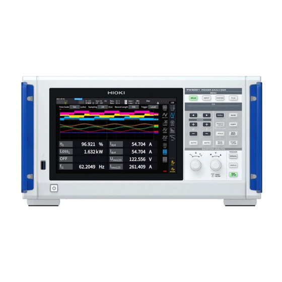
PW8001
PW8001-01
PW8001-11
PW8001-02
PW8001-12
PW8001-03
PW8001-13
PW8001-04
PW8001-14
PW8001-05
PW8001-15
PW8001-06
PW8001-16
POWER ANALYZER
Read carefully before use.
Keep for future reference.
When using the instrument for
the first time
Safety Information
Measurement Procedure
Part Names and Functions
Dec. 2021 Edition 1
PW8001A961-00 21-12H
Troubleshooting
p. 8
Maintenance and Service
p. 12
Troubleshooting
p. 15
Dialogs
HIOKI PW8001A961-00
Instruction Manual
p. 231
p. 233
p. 236
*600627740*
EN
Advertisement
Table of Contents


Need help?
Do you have a question about the PW8001-01 and is the answer not in the manual?
Questions and answers