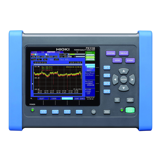
Hioki PW3198 Manual
Power quality analyzer
Hide thumbs
Also See for PW3198:
- Instruction manual (264 pages) ,
- Manual (9 pages) ,
- Measurement manual (2 pages)
Advertisement
Quick Links
Record and Analyze Power Supply Problems Simultaneously with a Single Unit
The New World Standard for Power Quality Analysis
Never Miss
the Moment
● Detect power supply problems and perform onsite troubleshooting
● Do preventive maintenance to avert accidents by managing the power quality
CAT
IV-600V Safety Standard
● Meets the CAT IV safety rating required to check an incoming power line
● Safe enough to measure up to 6,000Vpeak of transient overvoltage
Easy Setup
Function with PRESETS
● Just select the measurement course, wiring, and clamps
● Automatic one-step setup based on measurement conditions
Compliant with
International Standards
● International power quality measurement standard IEC 61000-4-30 Edition 2 Class A
● High precision with a basic voltage measurement accuracy of 0.1%
POWER QUALITY ANALYZER
AC FLEXIBLE CURRENT SENSOR
Introducing 2 new variations with a thinner cable!
Easy to loop around, even in confined spaces
CT9667-01
φ100 mm (3.94")
PW3198
Cable diameter
φ13 mm(0.51")
Legacy
product
New
additions
CT9667-01, -02
Cable diameter
φ7.4 mm(0.29")
CT9667-02
φ180 mm (7.09")
Advertisement

Related Manuals for Hioki PW3198


Summary of Contents for Hioki PW3198
- Page 1 POWER QUALITY ANALYZER PW3198 Record and Analyze Power Supply Problems Simultaneously with a Single Unit The New World Standard for Power Quality Analysis Never Miss the Moment ● Detect power supply problems and perform onsite troubleshooting ● Do preventive maintenance to avert accidents by managing the power quality IV-600V Safety Standard ●...
- Page 2 The quickest way to approach these problems is to understand the situation quickly and accurately. The PW3198 Power Quality Analyzer is ready to effectively solve your power supply problems. Troubleshooting Understand the actual power situation at the site where the problem is occurring (e.g., the equipment malfunction, fail-...
- Page 3 GPS box. Class Easy to set up - Just select the measurement course and the PW3198 will do the rest Simply choose the course based on the measurement objective and the necessary configurations will be set automatically.
- Page 4 The PW3198 can measure all waveforms of power, harmonic, and error events simultaneously. When a problem occurs with the equipment or system on your site, the PW3198 will help you detect the cause of the problem early and solve it quickly.
- Page 5 The PW3198 can simultaneously record 8,000 or more parameters, such as voltage, current, power, power factor, frequency, integral power, harmonic, and flicker, at the specified recording interval. The PW3198 never fails to capture the peak because it performs cal- culations continuously and records the maximum, minimum, and average values within the recording interval.
-
Page 6: Viewer Function
Analyze Recorded Data with a PC Using Application Software 9624-50 PQA-HiVIEW PRO Use Model 9624-50 PQA-HiVIEW PRO (version 2.00 or later) with a PC to analyze the data collected by the PW3198. Viewer Function Display and analyze the data recorded by the PW3198 POWER QUALITY ANALYZER. - Page 7 If your PC is not equipped with an SD memory on another line using Channel 4. card slot, simply connect a USB cable between the PW3198 and the PC. The PC will then recognize the SD memory card as Yes! Simultaneously! removable media.
- Page 8 Method Setup is very easy. Just install the PW3198 on the site, Select the “U Events” course in the PW3198 in the same way and measure the voltage, current, and power. To troubleshoot, as with the office equipment example.
-
Page 9: Measurement Items
Recording basic parameters and harmonics All Data (Full): Recording P&Harm items and inter-harmonics Memory data capacity SD memory card/ SDHC memory card 2G to 32GB Contact your HIOKI representative for special order larger capacity cards that offer the HIOKI guarantee. -
Page 10: Display Specifications
Slot : SD standard compliant Compatible card : SD memory card/ SDHC memory card (Use only HIOKI-approved SD memory cards) Supported memory capacity : SD memory card: Up to 2GB, SDHC memory card: Up to 32GB Media full processing : Saving of data to SD memory card is stopped... - Page 11 Measurement Specifications (For specifications when measuring 400Hz circuits, please inquire with your HIOKI distributor.) TIME PLOT The MAX/MIN/AVG of each recording interval for each parameter are recorded. EVENT When a power anomaly occurs, approx. 200ms instantaneous waveform is recorded. TRANSIENT When a transient overvoltage is detected, the 2ms instantaneous waveforms before and after the occurrence (total 4ms) are recorded.
- Page 12 Voltage DC value (ch4 only) TIME PLOT EVENT Measurement method Average value during approx. 20ms aggregation synchronized with the reference channel (CH4 only) Sampling frequency 200kHz Measurement range, resolution 600.00V, 0.01V Measurement accuracy ±0.3%rdg. ±0.08%f.s. Current DC value (ch4 only; when using compatible sensor) TIME PLOT EVENT Measurement method...
- Page 13 Total harmonic voltage/ Total harmonic current distortion factor TIME PLOT EVENT Display items THD-F (total harmonic distortion factor for the fundamental wave) THD-R (total harmonic distortion factor for the total harmonic including the fundamental wave) Measurement method Based on IEC61000-4-7:2002; Max. order: 50th Comparison window width 10 cycles (50 Hz), 12 cycles (60 Hz) No.
- Page 14 Clamp-on sensors specifications (Options) Clamp-on sensor CLAMP ON SENSOR 9694 CLAMP ON SENSOR 9660 CLAMP ON SENSOR 9661 Appearance Primary current rating 5A AC 100A AC 500A AC Output voltage 10mV/A AC AC 1mV/A AC AC 1mV/A AC Measurement range See input specifications Amplitude accuracy * ±0.3%rdg.±0.02%f.s.
- Page 15 CLAMP ON LEAK SENSOR 9675 Insulated Insulated conductor conductor Appearance Primary current rating 10A AC (Up to 5A on Model PW3198) Output voltage 100 mV/A AC Measurement range See input specifications (Cannot be used to measure power) Amplitude accuracy * ±1.0%rdg.±0.05%f.s. * ±1.0%rdg.±0.005%f.s.
- Page 16 φ15mm(0.59”) φ46mm(1.81”) *The AC/DC Auto-zero Current Sensor CT7731/CT7736/CT7742 cannot be used on its own with the PW3198. Be sure to use a set that includes the Display Unit CM7290, Output Cord L9095, and AC Adapter 9445-02 or 9445-03. CT9667-01 CT9667-02...
Need help?
Do you have a question about the PW3198 and is the answer not in the manual?
Questions and answers