Vega VEGASON 61 Operating Instructions Manual
Ultrasonic sensor for continuous level measuremen
Hide thumbs
Also See for VEGASON 61:
- Operating instructions manual (68 pages) ,
- Quick setup manual (24 pages) ,
- Operating instructions manual (52 pages)

Related Manuals for Vega VEGASON 61


Summary of Contents for Vega VEGASON 61
- Page 1 Operating Instructions Ultrasonic sensor for continuous level measurement VEGASON 61 Four-wire 4 … 20 mA/HART Document ID: 28778...
-
Page 2: Table Of Contents
8 Maintenance and fault rectification ..................45 8.1 Maintenance ........................45 Rectify faults ........................45 Exchanging the electronics module ................46 Software update ......................47 How to proceed if a repair is necessary ................47 Dismount..........................48 VEGASON 61 • Four-wire 4 … 20 mA/HART... - Page 3 10.4 Trademark ........................54 Safety instructions for Ex areas: Take note of the Ex specific safety instructions for Ex applications. These instructions are attached as documents to each instrument with Ex approval and are part of the operating instructions. Editing status: 2022-03-07 VEGASON 61 • Four-wire 4 … 20 mA/HART...
-
Page 4: About This Document
Symbols used Document ID This symbol on the front page of this instruction refers to the Docu- ment ID. By entering the Document ID on www.vega.com you will reach the document download. Information, note, tip: This symbol indicates helpful additional infor- mation and tips for successful work. -
Page 5: For Your Safety
During work on and with the device, the required personal protective equipment must always be worn. Appropriate use VEGASON 61 is a sensor for continuous level measurement. You can find detailed information about the area of application in chapter " Product description". Operational reliability is ensured only if the instrument is properly used according to the specifications in the operating instructions manual as well as possible supplementary instructions. -
Page 6: Fulfillment Of Namur Recommendations
That is why we have introduced an environment management system with the goal of continuously improving company environmental pro- tection. The environment management system is certified according to DIN EN ISO 14001. Please help us fulfil this obligation by observing the environmental instructions in this manual: • Chapter " Packaging, transport and storage" • Chapter " Disposal" VEGASON 61 • Four-wire 4 … 20 mA/HART... -
Page 7: Product Description
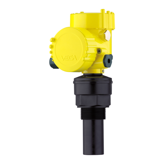
Housing with electronics • Housing cover, optionally available with display and adjustment module PLICSCOM The components are available in different versions. Fig. 1: VEGASON 61, Aluminium double chamber housing Housing cover with integrated PLICSCOM (optional) Housing with electronics, optionally available with plug connector 3 Process fitting with transducer Type label... -
Page 8: Principle Of Operation
Software version from 3.90 Principle of operation Application area VEGASON 61 is an ultrasonic sensor for continuous level measure- ment. It is suitable for liquids and solids in virtually all industries, particularly in the water and waste water industry. Functional principle The transducer of the ultrasonic sensor transmits short ultrasonic pulses to the measured product. These pulses are reflected by... -
Page 9: Packaging, Transport And Storage
VEGACONNECT The interface adapter VEGACONNECT enables the connection of communication-capable instruments to the USB interface of a PC. VEGADIS 81 The VEGADIS 81 is an external display and adjustment unit for VEGA plics sensors. ® VEGADIS 82 VEGADIS 82 is suitable for measured value indication and adjustment of sensors with HART protocol. - Page 10 HART sensors. Protective cover The protective cover protects the sensor housing against soiling and intense heat from solar radiation. Flanges Screwed flanges are available in different versions according to the following standards: DIN 2501, EN 1092-1, BS 10, ASME B 16.5, JIS B 2210-1984, GOST 12821-80. VEGASON 61 • Four-wire 4 … 20 mA/HART...
-
Page 11: Mounting
(e.g. through cleaning processes) or on cooled or heated vessels. To maintain the housing protection, make sure that the housing lid is closed during operation and locked, if necessary. VEGASON 61 • Four-wire 4 … 20 mA/HART... - Page 12 " Technical data". Fig. 3: Blocking distance to the max. level blocking distance Reference plane Information: If the medium reaches the transducer, buildup can form on it and cause faulty measurements later on. VEGASON 61 • Four-wire 4 … 20 mA/HART...
-
Page 13: Mounting Instructions
With pressures under -0.2 bar (-20 kPa) you should use a different measuring principle, e.g. radar or guided radar (TDR). Mounting instructions Screwing in Screw VEGASON 61 into the mounting socket with an appropriate spanner applied to the hexagon of the process fitting. Max. torque see chapter " Technical data". Warning: The housing must not be used to screw the instrument in! Applying tightening force can damage internal parts of the housing. - Page 14 Fig. 6: Vessel with conical bottom Nozzle Socket pieces should be dimensioned so that the lower end of the transducer protrudes at least 10 mm (0.394 in) out of the nozzle. VEGASON 61 • Four-wire 4 … 20 mA/HART...
- Page 15 4 Mounting Fig. 7: Recommended socket mounting If the reflective properties of the medium are good, you can mount VEGASON 61 on sockets which are higher than the length of the transducer. You will find recommended values for socket heights in the following illustration. The socket end should be smooth and burr-free, if possible also rounded. Carry out a false signal suppression.
- Page 16 α α α α Fig. 11: Cover flat, large-area profiles with deflectors Agitators If there are agitators in the vessel, a false signal suppression should be carried out with the agitators in motion. This ensures that the interfering reflections from the agitators are saved with the blades in different positions. VEGASON 61 • Four-wire 4 … 20 mA/HART...
- Page 17 If there are strong air currents in the vessel, e.g. due to strong winds in outdoor installations or air turbulence, e.g. by cyclone extraction you should mount VEGASON 61 in a standpipe or use a different measuring principle, e.g. radar or guided radar (TDR). VEGASON 61 • Four-wire 4 … 20 mA/HART...
- Page 18 Fig. 14: Standpipe in the tank Vent hole: ø 5 … 10 mm (0.197 … 0.394 in) VEGASON 61 can be used from tube diameters of 40 mm (1.575 in). Avoid large gaps and thick welding joints when connecting the tubes.
- Page 19 • Installation of the sensor at the inlet side • Installation in the centre of the flume and vertical to the liquid surface • Distance to the Venturi flume • Distance of the sensor to the max. height of damming by taking the blocking distance into account VEGASON 61 • Four-wire 4 … 20 mA/HART...
-
Page 20: Connecting To Power Supply
The ground terminal on the outside of the housing must be connected to the ground potential (low impedance). In Ex systems, the grounding is carried out according to the installa- tion regulations. VEGASON 61 • Four-wire 4 … 20 mA/HART... -
Page 21: Connection Procedure
9. Connect the shielding to the internal ground terminal, connect the external ground terminal to potential equalisation 10. Tighten the compression nut of the cable entry gland. The seal ring must completely encircle the cable VEGASON 61 • Four-wire 4 … 20 mA/HART... -
Page 22: Wiring Plan, Double Chamber Housing
I 2 C 5 6 7 8 Fig. 19: Electronics compartment - double chamber housing Plug connector for VEGACONNECT (I²C interface) Internal connection cable to the connection compartment Terminals for VEGADIS 81 VEGASON 61 • Four-wire 4 … 20 mA/HART... -
Page 23: Switch-On Phase
Fig. 21: Wiring plan - double chamber housing Voltage supply Signal output Switch-on phase Switch-on phase After connecting VEGASON 61 to power supply or after a voltage recurrence, the instrument carries out a self-check for approx. 30 seconds: • Internal check of the electronics •... - Page 24 5 Connecting to power supply Then the corresponding current is output to the cable (the value corresponds to the actual level as well as the settings already carried out, e.g. factory setting). VEGASON 61 • Four-wire 4 … 20 mA/HART...
-
Page 25: Set Up With The Display And Adjustment Module Plicscom
The display and adjustment module is powered by the sensor, an ad- ditional connection is not necessary. Fig. 22: Insert display and adjustment module Note: If you intend to retrofit the instrument with a display and adjustment module for continuous measured value indication, a higher lid with an inspection glass is required. VEGASON 61 • Four-wire 4 … 20 mA/HART... -
Page 26: Adjustment System
The pen oper- ates the four keys of the display and adjustment module right through the closed lid (with inspection window) of the sensor housing. VEGASON 61 • Four-wire 4 … 20 mA/HART... -
Page 27: Setup Steps
The actual level is then calculated on the basis of these entered values. At the same time, the operating range of the sensor is limited from maximum range to the requested range. VEGASON 61 • Four-wire 4 … 20 mA/HART... - Page 28 [+] and save with [OK]. The cursor jumps now to the distance value. 4. Enter the distance value in m for empty vessel (e.g. distance from the sensor to the vessel bottom) corresponding to the percentage value. VEGASON 61 • Four-wire 4 … 20 mA/HART...
- Page 29 Stilling tube", " Open vessel" or " Stirred vessel", with " Solid", " Silo" or " Bunker". Vessel shape Storage tank Enter the requested parameters via the appropriate keys, save your settings and jump to the next menu item with the [->] key. VEGASON 61 • Four-wire 4 … 20 mA/HART...
- Page 30 Display - Indicated value In the menu item " Display" you can define how the measured value should be presented on the display. The following indication values are available: • Height • Distance • Current • Scaled • Percent VEGASON 61 • Four-wire 4 … 20 mA/HART...
- Page 31 Diagnosis - Peak value The respective min. and max. measured values are saved in the sen- sor. The values are displayed in the menu item " Peak values". • Min. and max. distance in m(d) • Min. and max. temperature VEGASON 61 • Four-wire 4 … 20 mA/HART...
- Page 32 A comparison of the echo curve and the false echo curve allows a entation more detailled evaluation of measurement reliability. The selected curve is updated continuously. With the [OK] key, a submenu with zoom functions is opened. VEGASON 61 • Four-wire 4 … 20 mA/HART...
- Page 33 Check the distance to the medium surface, because if an incorrect (too large) value is entered, the existing level will be saved as a false signal. The level would then no longer be detectable in this area. VEGASON 61 • Four-wire 4 … 20 mA/HART...
- Page 34 The menu item " Extended setting" offers the possibility to optimise Service - Extended set- ting VEGASON 61 for applications in which the level changes very quickly. To do this, select the function " Quick level change > 1 m/min.". Extended setting quick level change > 1 m/min.
- Page 35 Current output - min. current 3.8 mA Current output - failure < 3.6 mA Sensor-specific basic adjustment. Depending on the sensor type, see chapter "Technical data". Depending on the sensor type, see chapter "Technical data". VEGASON 61 • Four-wire 4 … 20 mA/HART...
- Page 36 SIL via the indicating and adjustment module. The SIL factory setting cannot be deactivated by the user. Special parameters are parameters which are set customer-specifically on the service level with the adjustment software PACTware. VEGASON 61 • Four-wire 4 … 20 mA/HART...
- Page 37 Language The following safety-relevant data are not read out or written: • HART mode • The 4 … 20 mA signal of the sensor is switched off. The sensor uses a constant current of 4 mA. The measuring signal is transmitted exclusively as a digital HART signal. VEGASON 61 • Four-wire 4 … 20 mA/HART...
- Page 38 Date of last change using PC: Date of the last change of sensor parameters via PC Last change using PC • Sensor details, e.g. approval, process fitting, seal, measuring cell, measuring range, electronics, housing, cable entry, plug, cable length etc. Sensor characteristics Display now? VEGASON 61 • Four-wire 4 … 20 mA/HART...
-
Page 39: Menu Schematic
Peak value indicator Measurement reliability Curve selection Echo curve Distance min.: 0.234 m(d) 36 dB Distance max.: 5.385 m(d) Device status Echo curve Presentation of the echo curve T-min.: 16.5 °C T-min.: 37.5 °C VEGASON 61 • Four-wire 4 … 20 mA/HART... -
Page 40: Saving The Parameterisation Data
The data remain permanently stored there even if the sensor supply fails. The proce- dure is described in menu item " Copy sensor data". VEGASON 61 • Four-wire 4 … 20 mA/HART... -
Page 41: Set Up With Pactware And Other Adjustment Programs
Fig. 27: Connection via interface adapter VEGACONNECT external I²C bus (com.) interface on the sensor I²C connection cable of VEGACONNECT Interface adapter VEGACONNECT USB cable to the PC Necessary components: • VEGASON 61 VEGASON 61 • Four-wire 4 … 20 mA/HART... -
Page 42: Parameter Adjustment With Pactware
Power supply unit or processing system Note: With power supply units with integrated HART resistance (internal resistance approx. 250 Ω), an additional external resistance is not necessary. This applies, e. g. to the VEGA instruments VEGATRENN 149A, VEGADIS 371, VEGAMET 381. Common Ex separators are also usually equipped with a sufficient current limitation resistance. In such cases, VEGACONNECT 4 can be connected parallel to the 4 …... -
Page 43: Parameter Adjustment With Ams™ And Pdm
The standard version is available as a download under www.vega.com/downloads. The full version is available on CD from the agency serving you. Parameter adjustment with AMS™ and PDM For VEGA sensors, instrument descriptions for the adjustment programs AMS™ and PDM are available as DD or EDD. The instru-... -
Page 44: Saving The Parameterisation Data
It is recommended to document or save the parameter adjustment data. That way they are available for multiple use or service purposes. The VEGA DTM Collection and PACTware in the licensed, profession- al version provide suitable tools for systematic project documentation and storage. VEGASON 61 • Four-wire 4 … 20 mA/HART... -
Page 45: Maintenance And Fault Rectification
24 hour service hotline Should these measures not be successful, please call in urgent cases the VEGA service hotline under the phone no. +49 1805 858550. The hotline is manned 7 days a week round-the-clock. Since we offer this service worldwide, the support is only available in the English language. The service is free, only standard call charges are incurred. -
Page 46: Exchanging The Electronics Module
In both cases, the sensor serial number is necessary. The serial num- bers are stated on the type label of the instrument, inside the housing or on the delivery note. Information: When loading on site, the order data must first be downloaded from the Internet (see operating instructions " Electronics module"). VEGASON 61 • Four-wire 4 … 20 mA/HART... -
Page 47: Software Update
Attach the completed form and, if need be, also a safety data sheet outside on the packaging • Ask the agency serving you to get the address for the return ship- ment. You can find the agency on our homepage. VEGASON 61 • Four-wire 4 … 20 mA/HART... -
Page 48: Dismount
If personal data is stored on the old device to be disposed of, delete it before disposal. If you have no way to dispose of the old instrument properly, please contact us concerning return and disposal. VEGASON 61 • Four-wire 4 … 20 mA/HART... -
Page 49: Supplement
4 … 20 mA/HART (active) HART output values Ʋ HART value (Primary Value) Distance to the level Ʋ HART value (Secondary Value) Temperature Glass (with Aluminium and stainless steel precision casting housing) VEGASON 61 • Four-wire 4 … 20 mA/HART... - Page 50 0.06 %/10 K zero signal (temperature error) With inductive load ohmic share min. 25 Ω/mH. Incl. non-linearity, hysteresis and non-repeatability. Time to output the correct level (with max. 10 % deviation) after a sudden level change. Relating to the nominal measuring range. VEGASON 61 • Four-wire 4 … 20 mA/HART...
- Page 51 25 m (82.02 ft) Protection rating Ʋ unassembled IP20 Ʋ Mounted in the housing without lid IP40 Materials Ʋ Housing Ʋ Inspection window Polyester foil Functional safety SIL non-reactive Tested according to the guidelines of German Lloyd, GL directive 2. VEGASON 61 • Four-wire 4 … 20 mA/HART...
- Page 52 For that reason the associated approval documents of these instruments have to be carefully noted. They are part of the delivery or can be downloaded by entering the serial number of your instrument into the search field under www.vega.com as well as in the general download area. When used with fulfilled housing protection...
-
Page 53: Dimensions
") ø 74mm ") Fig. 32: VEGASON 61 Dead zone: 0.25 m (0.82 ft) Measuring range: with liquids up to 5 m (16.4 ft), with solids up to 2 m (6.562 ft) VEGASON 61 • Four-wire 4 … 20 mA/HART... -
Page 54: Industrial Property Rights
Les lignes de produits VEGA sont globalement protégées par des droits de propriété intellec- tuelle. Pour plus d'informations, on pourra se référer au site www.vega.com. VEGA lineas de productos están protegidas por los derechos en el campo de la propiedad indus- trial. Para mayor información revise la pagina web www.vega.com. - Page 55 Notes VEGASON 61 • Four-wire 4 … 20 mA/HART...
- Page 56 Subject to change without prior notice © VEGA Grieshaber KG, Schiltach/Germany 2022 VEGA Grieshaber KG Am Hohenstein 113 Phone +49 7836 50-0 77761 Schiltach E-mail: info.de@vega.com...
Need help?
Do you have a question about the VEGASON 61 and is the answer not in the manual?
Questions and answers