Vega VEGASON 62 Operating Instructions Manual
Ultrasonic sensor for continuous level measurement
Hide thumbs
Also See for VEGASON 62:
- Operating instructions manual (68 pages) ,
- Quick setup manual (24 pages) ,
- Operating instructions manual (52 pages)

Related Manuals for Vega VEGASON 62


Summary of Contents for Vega VEGASON 62
-
Page 1: Operating Instructions
Operating Instructions Ultrasonic sensor for continuous level measurement VEGASON 62 4 … 20 mA/HART - four-wire Document ID: 28779... -
Page 2: Table Of Contents
Maintenance ........................45 Rectify faults ........................45 Exchanging the electronics module ................46 Software update ......................46 How to proceed if a repair is necessary ................47 Dismount Dismounting steps......................48 VEGASON 62 • 4 … 20 mA/HART - four-wire... - Page 3 10.2 Dimensions ........................52 Safety instructions for Ex areas Take note of the Ex specific safety instructions for Ex applications. These instructions are attached as documents to each instrument with Ex approval and are part of the operating instructions manual. Editing status: 2015-05-21 VEGASON 62 • 4 … 20 mA/HART - four-wire...
-
Page 4: About This Document
This arrow indicates a single action. Sequence of actions Numbers set in front indicate successive steps in a procedure. Battery disposal This symbol indicates special information about the disposal of bat- teries and accumulators. VEGASON 62 • 4 … 20 mA/HART - four-wire... -
Page 5: For Your Safety
During work on and with the device the required personal protective equipment must always be worn. Appropriate use VEGASON 62 is a sensor for continuous level measurement. You can find detailed information about the area of application in chapter "Product description". Operational reliability is ensured only if the instrument is properly used according to the specifications in the operating instructions manual as well as possible supplementary instructions. -
Page 6: Safety Label On The Instrument
That is why we have introduced an environment management system with the goal of continuously improving company environmental pro- tection. The environment management system is certified according to DIN EN ISO 14001. Please help us fulfill this obligation by observing the environmental instructions in this manual: • Chapter "Packaging, transport and storage" • Chapter "Disposal" VEGASON 62 • 4 … 20 mA/HART - four-wire... -
Page 7: Product Description
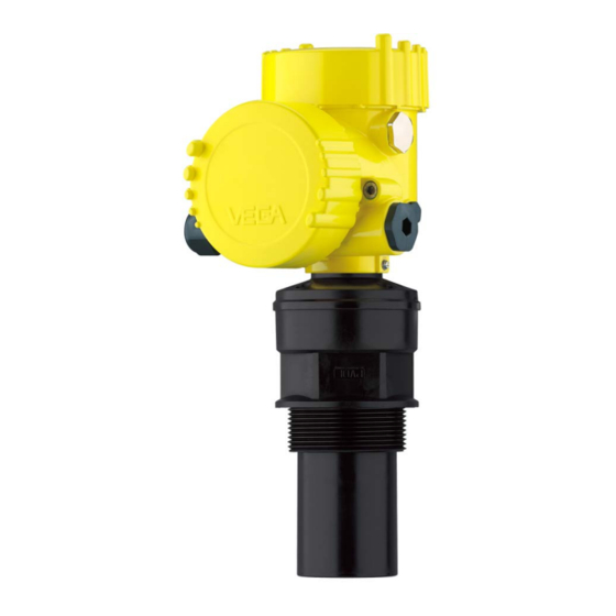
Housing with electronics • Housing cover, optionally available with display and adjustment module PLICSCOM The components are available in different versions. Fig. 1: VEGASON 62 with Alu double chamber housing Housing cover with integrated PLICSCOM (optional) Housing with electronics, optionally available with plug connector 3 Process fitting with transducer Type label... -
Page 8: Principle Of Operation
• Software version ≤ 3.8 Principle of operation Application area VEGASON 62 is an ultrasonic sensor for continuous level measure- ment. It is suitable for liquids and solids in virtually all industries, particularly in the water and waste water industry. Functional principle The transducer of the ultrasonic sensor transmits short ultrasonic pulses to the measured product. These pulses are reflected by... -
Page 9: Accessories And Replacement Parts
You can find further information in the operating instructions "Interface adapter VEGACONNECT" (Document-ID 32628). VEGADIS 81 The VEGADIS 81 is an external display and adjustment unit for VEGA plics sensors. ® For sensors with double chamber housing the interface adapter "DISADAPT"... - Page 10 "Flanges according to DIN-EN-ASME-JIS" (Document-ID 31088). Electronics module Electronics module "VEGASON series 60" is a replacement part for ultrasonic sensors of VEGASON series 60. A different version is avail- able for each type of signal output. You can find further information in the operating instructions "Elec- tronics module VEGASON series 60" (Document-ID 30206). VEGASON 62 • 4 … 20 mA/HART - four-wire...
-
Page 11: Mounting
Prior to setup you have to replace these protective caps with ap- proved cable glands or close the openings with suitable blind plugs. Reference plane for The reference plane for the measuring range is the lower edge of the measuring range transducer. Make sure that a minimum distance from the reference plane - the so-called dead zone, in which measurement is not possible - is VEGASON 62 • 4 … 20 mA/HART - four-wire... -
Page 12: Mounting Instructions
This influences the measuring result, particularly if the level is very low. With pressures under -0.2 bar (-20 kPa) you should use a different measuring principle, e.g. radar or guided microwave. Mounting instructions Screwing in Screw VEGASON 62 into the mounting socket with an appropriate spanner applied to the hexagon of the process fitting. Max. torque see chapter "Technical data". VEGASON 62 • 4 … 20 mA/HART - four-wire... - Page 13 In vessels with conical bottom it can be advantageous to mount the sensor in the center of the vessel, as measurement is then possible down to the lowest point of the vessel bottom. VEGASON 62 • 4 … 20 mA/HART - four-wire...
- Page 14 10 mm (0.394 in) out of the socket. Fig. 7: Recommended socket mounting If the reflective properties of the medium are good, you can mount VEGASON 62 on sockets which are higher than the length of the transducer. You will find recommended values for socket heights in the following illustration. The socket end should be smooth and burr-free, if possible also rounded.
- Page 15 "clear view" to the measured product. In case of existing vessel installations, a false echo storage should be carried out during setup. VEGASON 62 • 4 … 20 mA/HART - four-wire...
- Page 16 If there are agitators in the vessel, a false signal storage should be carried out with the agitators in motion. This ensures that the interfer- ing reflections from the agitators are saved with the blades in different positions. Fig. 12: Agitators Do not mount the instruments in or above the filling stream. Make sure Inflowing medium that you detect the product surface, not the inflowing product. VEGASON 62 • 4 … 20 mA/HART - four-wire...
- Page 17 (TDR). Standpipe measurement By using a standpipe (surge or bypass tube), the influence of vessel installations, foam generation and turbulence is excluded. Standpipes must extend all the way down to the requested min. level, as measurement is only possible within the tube. VEGASON 62 • 4 … 20 mA/HART - four-wire...
- Page 18 Fig. 14: Standpipe in the tank Vent hole: ø 5 … 10 mm (0.197 … 0.394 in) VEGASON 62 can be used from tube diameters of 50 mm (1.969 in). Avoid large gaps and thick welding joints when connecting the tubes.
- Page 19 = max. filling of the flume; B = tightest constriction in the flume max. Position sensor 2 Venturi flume In general, the following points must be observed: • Installation of the sensor at the inlet side • Installation in the centre of the flume and vertical to the liquid surface • Distance to the Venturi flume • Min. distance of the sensor to max. storage level VEGASON 62 • 4 … 20 mA/HART - four-wire...
-
Page 20: Connecting To Power Supply
In Ex systems, the grounding is carried out according to the installa- tion regulations. With the Exd version, the minus side of the signal output is galvani- cally connected to ground via protective diodes. When connecting the instrument to a grounded PLC, equalising currents can flow in case VEGASON 62 • 4 … 20 mA/HART - four-wire... -
Page 21: Connection Procedure
11. Connect the lead cable for power supply in the same way accord- ing to the wiring plan, in addition connect the ground conductor to the inner ground terminal. 12. Screw the housing lid back on The electrical connection is finished. VEGASON 62 • 4 … 20 mA/HART - four-wire... -
Page 22: Wiring Plan, Double Chamber Housing
Fig. 18: Double chamber housing Housing cover, connection compartment Blind plug or plug M12 x 1 for VEGADIS 61 (optional) Housing cover, electronics compartment Filter element for air pressure compensation Cable gland VEGASON 62 • 4 … 20 mA/HART - four-wire... - Page 23 4... 20mA L1 N Fig. 20: Terminal compartment, double chamber housing Spring-loaded terminals for signal output Ground terminal for connection of the ground conductor and screen Spring-loaded terminals for voltage supply VEGASON 62 • 4 … 20 mA/HART - four-wire...
-
Page 24: Switch-On Phase
Fig. 21: Wiring plan, double chamber housing Voltage supply Signal output Switch-on phase Switch-on phase After connecting VEGASON 62 to power supply or after a voltage recurrence, the instrument carries out a self-check for approx. 30 seconds: • Internal check of the electronics •... -
Page 25: Set Up With The Display And Adjustment Module Plicscom
The display and adjustment module is powered by the sensor, an ad- ditional connection is not necessary. Fig. 22: Insert display and adjustment module Note: If you intend to retrofit the instrument with a display and adjustment module for continuous measured value indication, a higher lid with an inspection glass is required. VEGASON 62 • 4 … 20 mA/HART - four-wire... -
Page 26: Adjustment System
By pushing the [OK] and [ESC] keys simultaneously for more than 5 s, a return to the basic menu is caused. The menu language is then switched over to "English". VEGASON 62 • 4 … 20 mA/HART - four-wire... -
Page 27: Setup Steps
These settings can be made ahead of time without the instrument having to be installed. Basic adjustment - Min. Proceed as follows: adjustment VEGASON 62 • 4 … 20 mA/HART - four-wire... - Page 28 (with liquids); dust generation, material cones and echoes from the vessel wall (with solids). To adapt the sensor to these different conditions, you should first select "Liquid" or "Solid". Medium Liquid VEGASON 62 • 4 … 20 mA/HART - four-wire...
- Page 29 "Display". Linearisation curve Linear Enter the requested parameters via the appropriate keys, save your settings and jump to the next menu item with the [->] key. VEGASON 62 • 4 … 20 mA/HART - four-wire...
- Page 30 "Display" and the adjustment unit in the menu "Device settings": • Indication value "Distance": Presentation of the measured value in the selected adjustment unit, e.g. m(d). Displayed value ▼ Scaled Display unit ▼ Volume ▼ VEGASON 62 • 4 … 20 mA/HART - four-wire...
- Page 31 Diagnosis - Curve selec- tion strength of the echoes over the measuring range. The unit of signal strength is "dB". The signal strength enables the jusgement of the quality of the measurement. VEGASON 62 • 4 … 20 mA/HART - four-wire...
- Page 32 A false echo memory should be created with low level so that all potential interfering reflec- tions can be detected. VEGASON 62 • 4 … 20 mA/HART - four-wire...
- Page 33 Service - Extended set- The menu item "Extended setting" offers the possibility to optimise ting VEGASON 62 for applications in which the level changes very quickly. To do this, select the function "Quick level change > 1 m/min.". Extended setting quick level change > 1 m/min.
- Page 34 Value of the current output in case of failure, e.g. if no valid measured value is delivered. This value is not underrun during operation. This value is not exceeded during operation. VEGASON 62 • 4 … 20 mA/HART - four-wire...
- Page 35 The following languages are available, e.g. in software version 3.50: • Deutsch • English Sensor-specific basic adjustment. Depending on the sensor type, see chapter "Technical data". Special parameters are parameters which are set customer-specifically on the service level with the adjustment software PACTware. VEGASON 62 • 4 … 20 mA/HART - four-wire...
- Page 36 "Display and adjustment module". The following data are read out or written with this function: The 4 … 20 mA signal of the HART sensor is switched off. The sensor consumes a constant current of 4 mA. The measuring signal is transmitted exclusively as digital HART signal. VEGASON 62 • 4 … 20 mA/HART - four-wire...
- Page 37 In this menu item the most important sensor information can be displayed: • Instrument type • Serial number: 8-digit number, e.g. 12345678 Instrument type Serial number 12345678 • Date of manufacture: Date of the factory calibration, e.g. 24. March 2015 • Software version: Edition of the sensor software, e.g. 3.80 VEGASON 62 • 4 … 20 mA/HART - four-wire...
-
Page 38: Menu Schematic
Basic adjustment Display Diagnostics Service Info Min. adjustment Max. adjustment Medium Vessel form 0.00 % 100.00 % Liquid Storage tank 4.000 m(d) 1.000 m(d) 3.000 m(d) 2.000 m(d) Damping Linearisation curve Sensor-TAG Linear Sensor VEGASON 62 • 4 … 20 mA/HART - four-wire... - Page 39 Fail.mode: < 3.6 mA ▼ Min. current: 3.8 mA Reset Unit of measurement Language ▼ ▼ ▼ Select reset? m(d) Deutsch Not activated select? HART mode Copy sensor data 4.10 4.11 Standard Copy sensor data? Enable? Address 0 VEGASON 62 • 4 … 20 mA/HART - four-wire...
-
Page 40: Saving The Parameter Adjustment Data
They are thus available for multiple use or service purposes. If VEGASON 62 is equipped with a display and adjustment module, the most important data can be read out of the sensor into the display and adjustment module. -
Page 41: Set Up With Pactware And Other Adjustment Programs
Fig. 26: Connection via VEGACONNECT externally I²C bus (com.) interface on the sensor I²C connection cable of VEGACONNECT VEGACONNECT USB cable to the PC Necessary components: • VEGASON 62 • PC with PACTware and suitable VEGA DTM VEGASON 62 • 4 … 20 mA/HART - four-wire... -
Page 42: Parameter Adjustment With Pactware
Power supply unit or processing system Note: With power supply units with integrated HART resistance (internal resistance approx. 250 Ω), an additional external resistance is not necessary. This applies, e. g. to the VEGA instruments VEGATRENN 149A, VEGADIS 371, VEGAMET 381. Common Ex separators are also usually equipped with a sufficient current limitation resistance. In such cases, VEGACONNECT 4 can be connected parallel to the 4 …... -
Page 43: Parameter Adjustment With Ams™ And Pdm
Parameter adjustment with AMS™ and PDM For VEGA sensors, instrument descriptions for the adjustment programs AMS™ and PDM are available as DD or EDD. The instru- ment descriptions are already implemented in the current versions of AMS™ and PDM. For older versions of AMS™ and PDM, a free-of-charge download is available via Internet. Move via www.vega.com and "Downloads" to "Software". VEGASON 62 • 4 … 20 mA/HART - four-wire... -
Page 44: Saving The Parameter Adjustment Data
It is recommended to document or save the parameter adjustment data. That way they are available for multiple use or service purposes. The VEGA DTM Collection and PACTware in the licensed, profession- al version provide suitable tools for systematic project documentation and storage. VEGASON 62 • 4 … 20 mA/HART - four-wire... -
Page 45: Maintenance And Fault Rectification
24 hour service hotline Should these measures not be successful, please call in urgent cases the VEGA service hotline under the phone no. +49 1805 858550. The hotline is manned 7 days a week round-the-clock. Since we offer this service worldwide, the support is only available in the English language. The service is free, only standard call charges are incurred. -
Page 46: Exchanging The Electronics Module
The electronics modules are adapted to the respective sensor and distinguish also in the signal output or power supply. Software update The following components are required to update the instrument software: • Instrument • Voltage supply VEGASON 62 • 4 … 20 mA/HART - four-wire... -
Page 47: How To Proceed If A Repair Is Necessary
Attach the completed form and, if need be, also a safety data sheet outside on the packaging • Please contact the agency serving you to get the address for the return shipment. You can find the agency on our home page www.vega.com. VEGASON 62 • 4 … 20 mA/HART - four-wire... -
Page 48: Dismount
WEEE directive. Correct disposal avoids negative effects on humans and the environ- ment and ensures recycling of useful raw materials. Materials: see chapter "Technical data" If you have no way to dispose of the old instrument properly, please contact us concerning return and disposal. VEGASON 62 • 4 … 20 mA/HART - four-wire... -
Page 49: Technical Data
Measuring range Ʋ Liquids up to 8 m (26.25 ft) Ʋ Bulk solids up to 3.5 m (11.48 ft) Dead zone 0.4 m (1.312 ft) With inductive load ohmic share min. 25 Ω/mH. VEGASON 62 • 4 … 20 mA/HART - four-wire... - Page 50 -40 … +70 °C (-40 … +158 °F) ture Time to output the correct level (with max. 10 % deviation) after a sudden level change. Incl. non-linearity, hysteresis and non-repeatability. Relating to the nominal measuring range. VEGASON 62 • 4 … 20 mA/HART - four-wire...
- Page 51 Ʋ up to 2000 m (6562 ft) above sea level III Ʋ up to 5000 m (16404 ft) above sea III - Only with connected overvoltage protection level Tested according to the guidelines of German Lloyd, GL directive 2. VEGASON 62 • 4 … 20 mA/HART - four-wire...
-
Page 52: Dimensions
For that reason the associated approval documents of these instruments have to be carefully noted. They are part of the delivery or can be downloaded under www.vega.com via "VEGA Tools" and "Instrument search" as well as via "Downloads" and "Approvals". - Page 53 Les lignes de produits VEGA sont globalement protégées par des droits de propriété intellec- tuelle. Pour plus d'informations, on pourra se référer au site www.vega.com. VEGA lineas de productos están protegidas por los derechos en el campo de la propiedad indus- trial. Para mayor información revise la pagina web www.vega.com.
- Page 54 Notes VEGASON 62 • 4 … 20 mA/HART - four-wire...
- Page 55 Notes VEGASON 62 • 4 … 20 mA/HART - four-wire...
- Page 56 Subject to change without prior notice © VEGA Grieshaber KG, Schiltach/Germany 2015 VEGA Grieshaber KG Phone +49 7836 50-0 Am Hohenstein 113...
Need help?
Do you have a question about the VEGASON 62 and is the answer not in the manual?
Questions and answers