Vega VEGASON 61 Operating Instructions Manual
Foundation fieldbus
Hide thumbs
Also See for VEGASON 61:
- Operating instructions manual (68 pages) ,
- Quick setup manual (24 pages) ,
- Operating instructions manual (56 pages)
Table of Contents
Advertisement
Quick Links
Advertisement
Table of Contents

Related Manuals for Vega VEGASON 61


Summary of Contents for Vega VEGASON 61
-
Page 1: Operating Instructions
Operating Instructions VEGASON 61 Foundation Fieldbus Ultrasonic... -
Page 2: Table Of Contents
Parameter adjustment with AMS™ ....40 Saving the parameter adjustment data ... . 40 VEGASON 61 • Foundation Fieldbus... - Page 3 Instructions manuals for accessories and replacement parts Tip: To ensure reliable setup and operation of your VEGASON 61, we offer accessories and replacement parts. The associated documents are: 27835 - Indicating and adjustment module PLICSCOM 32628 - Interface adapter VEGACONNECT...
-
Page 4: About This Document
This symbol indicates special instructions for Ex applications. List The dot set in front indicates a list with no implied sequence. à Action This arrow indicates a single action. Sequence Numbers set in front indicate successive steps in a procedure. VEGASON 61 • Foundation Fieldbus... -
Page 5: For Your Safety
During work on and with the device the required personal protective equipment must always be worn. 2.2 Appropriate use VEGASON 61 is a sensor for continuous level measurement. You can find detailed information on the application range in chapter "Product description". -
Page 6: Safety Approval Markings And Safety Tips
The range of available functions depends on the respective software version of the individual components. The software version of VEGASON 61 can be determined as follows: via PACTware on the type label of the electronics via the indicating and adjustment module You can view all software histories on our website www.vega.com. - Page 7 2 For your safety Chapter "Packaging, transport and storage" Chapter "Disposal" VEGASON 61 • Foundation Fieldbus...
-
Page 8: Product Description
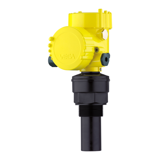
Housing cover, optionally available with indicating and adjustment module PLICSCOM The components are available in different versions. Fig. 1: VEGASON 61 - version with plastic housing Housing cover with integrated PLICSCOM (optional) Housing with electronics, optionally available with plug connector Process fitting with transducer... -
Page 9: Principle Of Operation
Foundation Fieldbus". The appropriate certificates are also available there. A CD with the appropriate files and certificates can be ordered via e-mail under info@de.vega.com or by phone from one of the VEGA agencies under the order number "DRIVER.S". The backlight of the indicating and adjustment module is powered by the sensor. -
Page 10: Operation
3 Product description 3.3 Operation VEGASON 61 can be adjusted with different adjustment media: with indicating and adjustment module with the suitable VEGA DTM in conjunction with an adjustment software according to the FDT/DTM standard, e.g. PACTware and a configuration tool... -
Page 11: Mounting
Make sure that a min. distance - the so called dead zone - below the reference plane is maintained in which a measurement is not possible. The exact value of the dead zone is stated in chapter "Technical data". VEGASON 61 • Foundation Fieldbus... - Page 12 (max. measuring distance) Measuring range Gauge pressure in the vessel does not influence VEGASON 61. Low Pressure/Vacuum pressure or vacuum does, however, damp the ultrasonic pulses. This influences the measuring result, particularly if the level is very low.
-
Page 13: Mounting Instructions
4 Mounting 4.2 Mounting instructions Screw VEGASON 61 into the mounting socket with an appropriate Screwing in spanner applied to the hexagon of the process fitting. Max. torque see chapter "Technical data". Warning: The housing must not be used to screw the instrument in! Applying tightening force can damage internal parts of the housing. - Page 14 Fig. 7: Recommended socket mounting If the reflective properties of the medium are good, you can mount VEGASON 61 on sockets higher than the transducer length. You will find recommended values for socket heights in the following illustration. The socket end should be smooth and burr-free, if possible also rounded.
- Page 15 Fig. 9: Alignment in liquids To reduce the min. distance to the medium, you can also mount VEGASON 61 with a beam deflector. By doing this, it is possible to fill the vessel nearly to maximum. Such an arrangement is suitable primarily for open vessels such as e.g.
- Page 16 If there are agitators in the vessel, a false echo storage should be carried out with the agitators in motion. This ensures that the interfering reflections from the agitators are saved with the blades in different positions. Fig. 12: Agitators VEGASON 61 • Foundation Fieldbus...
- Page 17 If there are strong air currents in the vessel, e.g. due to strong winds in outdoor installations or air turbulence, e.g. by cyclone extraction you should mount VEGASON 61 in a standpipe or use a different measuring principle, e.g. radar or guided radar (TDR).
- Page 18 Fig. 14: Standpipe in tank Vent hole: ø 5 … 10 mm (0.197 … 0.394 in) VEGASON 61 can be used from tube diameters of 40 mm (1.575 in). Avoid large gaps and thick welding joints when connecting the tubes.
-
Page 19: Connecting To Power Supply
Connect only in the complete absence of line voltage If overvoltage surges are expected, overvoltage arresters should be installed according to Foundation Fieldbus specification Tip: We recommend VEGA overvoltage arrester B63-32. Take note of In hazardous areas you should take note of the appropriate safety instruc- regulations, conformity and type approval certificates of the sensors... -
Page 20: Connection Procedure
1 cm (0.4 in) insulation from the ends of the individual wires Insert the cable through the cable gland into the sensor Lift the opening levers of the terminals with a screwdriver (see following illustration) VEGASON 61 • Foundation Fieldbus... -
Page 21: Wiring Plan, Single Chamber Housing
12 Screw the housing cover on The electrical connection is finished. 5.3 Wiring plan, single chamber housing The following illustrations apply to the non-Ex as well as to the Ex-ia version. VEGASON 61 • Foundation Fieldbus... - Page 22 Plug connector for VEGACONNECT (I²C interface) Spring-loaded terminals for connection of the external indication VEGADIS Ground terminal for connection of the cable screen Spring-loaded terminals for Foundation Fieldbus connection Simulation switch ("on" = mode for simulation release) VEGASON 61 • Foundation Fieldbus...
-
Page 23: Wiring Plan, Double Chamber Housing
Housing overview Fig. 19: Double chamber housing Housing cover, connection compartment Blind stopper or plug M12 x 1 for VEGADIS 61 (optional) Housing cover, electronics compartment Filter element for air pressure compensation Cable gland VEGASON 61 • Foundation Fieldbus... - Page 24 Display I ² C 5 6 7 8 Fig. 20: Electronics compartment, double chamber housing Simulation switch ("on" = mode for simulation release) Connection for VEGACONNECT (I²C interface) Internal connection cable to the connection compartment VEGASON 61 • Foundation Fieldbus...
- Page 25 Fig. 21: Connection compartment, double chamber housing Plug connector for VEGACONNECT (I²C interface) Ground terminal for connection of the cable screen Spring-loaded terminals for voltage supply Wiring plan I 2 C Fig. 22: Wiring plan, double chamber housing Voltage supply/Signal output VEGASON 61 • Foundation Fieldbus...
-
Page 26: Wiring Plan - Version Ip 66/Ip 68, 1 Bar
(+) and blue (-) to power supply or to the processing system Shielding 5.6 Switch on phase After VEGASON 61 is connected to voltage supply or after voltage Switch on phase recurrence, the instrument carries out a self-check for approx. 30 seconds. -
Page 27: Set Up With The Indicating And Adjustment Module Plicscom
Screw housing cover with inspection window tightly back on Removal is carried out in reverse order. The indicating and adjustment module is powered by the sensor, an additional connection is not necessary. VEGASON 61 • Foundation Fieldbus... - Page 28 Fig. 24: Mounting the indicating and adjustment module Note: If you intend to retrofit the instrument with an indicating and adjustment module for continuous measured value indication, a higher cover with an inspection glass is required. VEGASON 61 • Foundation Fieldbus...
-
Page 29: Adjustment System
The functions of the individual keys are shown in the above illustration. Approx. 10 minutes after the last pressing of a key, an automatic reset to measured value indication is triggered. Any values not confirmed with [OK] will not be saved. VEGASON 61 • Foundation Fieldbus... -
Page 30: Setup Procedure
6 Set up with the indicating and adjustment module PLICSCOM 6.4 Setup procedure After VEGASON 61 is connected to voltage supply or after voltage Switch on phase recurrence, the instrument carries out a self-check for approx. 30 seconds. The following steps are carried out: Internal check of the electronics Indication of the instrument type, the firmware as well as the... - Page 31 With solids, you can also choose between "Powder/Dust", "Granular/ Pellets" or "Ballast/Pebbels". Through this additional selection, the sensor is adapted perfectly to the product and measurement reliability, particularly in products with bad reflective properties, is considerably increased. VEGASON 61 • Foundation Fieldbus...
- Page 32 "Display". Linearisation curve linear Enter the requested parameter via the appropriate keys, save your settings and jump to the next menu item with the [->] key. VEGASON 61 • Foundation Fieldbus...
- Page 33 The filling level would then no longer be detectable in this area. Extended setting/Quick The menu item "Extended setting" offers the possibility to optimise VEGASON 61 for applications in which the level changes very quickly. level change For this reason, select the function "Quick level change > 1 m/min.".
- Page 34 Like basic adjustment, furthermore special parameters are reset to default values. Sensor-specific basic adjustment. Depending on the sensor type, see chapter "Technical data". Special parameters are parameters which are set customer-specifically on the service level with the adjustment software PACTware. VEGASON 61 • Foundation Fieldbus...
- Page 35 Additional adjustment and diagnosis options such as e.g. scaling, simulation or trend curve presentation are shown in the following menu schematic. You will find a detailed description of these menu items in the operating instructions manual "Indicating and adjustment module". VEGASON 61 • Foundation Fieldbus...
-
Page 36: Menu Schematic
10.000 m(d) 0.000 m(d) 1.245 m(d) 6.789 m(d) Damping Linearisation curve linear Display Basic adjustment ▶ Display Diagnostics Service Info Displayed value Lighting ▼ AI-Out Switched off Diagnostics Basic adjustment Display ▶ Diagnostics Service Info VEGASON 61 • Foundation Fieldbus... - Page 37 Date of manufacture Last change using PC < max. 32 characters > VEGASON 6x 10. April 2007 10. April 2007 Sensor-TAG (PD_TAG) Serial number Software version < max. 32 characters > 12345678 3.50 Sensor characteristics Display now? VEGASON 61 • Foundation Fieldbus...
-
Page 38: Saving The Parameter Adjustment Data
They are hence available for multiple use or service purposes. If VEGASON 61 is equipped with an indicating and adjustment module, the most important data can be read out of the sensor into indicating and adjustment module. The procedure is described in the operating instructions manual "Indicating and adjustment module"... -
Page 39: Setup With Pactware And Other Adjustment Programs
USB cable to the PC VEGACONNECT Sensor External connection via I²C interface TWIST Fig. 27: Connection via I²C connection cable I²C bus (com.) interface on the sensor I²C connection cable of VEGACONNECT VEGACONNECT USB cable to the PC VEGASON 61 • Foundation Fieldbus... -
Page 40: Parameter Adjustment With Pactware
A detailed description is available in the online help of PACTware and the VEGA DTMs. Note: Keep in mind that for setup of VEGASON 61, DTM-Collection in the actual version must be used. All currently available VEGA DTMs are provided in the DTM Collection on CD and can be obtained from the responsible VEGA agency for a token fee. -
Page 41: Maintenance And Fault Rectification
24 hour service hotline However, should these measures not be successful, call the VEGA service hotline in urgent cases under the phone no. +49 1805 858550. The hotline is available to you 7 days a week round-the-clock. Since we offer this service world-wide, the support is only available in the... -
Page 42: Exchanging The Electronics Module
In Ex applications only one instrument and one electronics module with respective Ex approval may be used. If there is no electronics module available on site, one can be ordered from the VEGA agency serving you. Sensor serial number The settings of the sensor must be downloaded into the new electronics module. -
Page 43: Software Update
Connect the sensor to power supply and provide connection from PC to the instrument via VEGACONNECT. Start PACTware and provide connection to the sensor, e.g. via the VEGA project assistant. Close the parameter window of the sensor, as far as open. - Page 44 8 Maintenance and fault rectification Please ask the agency serving you for the address of your return shipment. You can find the respective agency on our website www.vega.com under: "Company - VEGA worldwide" VEGASON 61 • Foundation Fieldbus...
-
Page 45: Dismounting
Correct disposal avoids negative effects to persons and environment and ensures recycling of useful raw materials. Materials: see chapter "Technical data" If you have no possibility to dispose of the old instrument professionally, please contact us concerning return and disposal. VEGASON 61 • Foundation Fieldbus... -
Page 46: Supplement
Measured value distance between lower edge of the transducer and product surface Measuring range up to 5 m (16.4 ft) Liquids up to 2 m (6.562 ft) Bulk solids 0.25 m (0.82 ft) Dead band VEGASON 61 • Foundation Fieldbus... - Page 47 4 m (13.123 ft) 5 m (16.404 ft) -10 mm (-0.394 in) -4 mm (-0.157 in) Fig. 28: Deviation VEGASON 61 Influence of the ambient temperature to the sensor electronics 0.06 %/10 K Average temperature coefficient of the zero signal (temperature error) Time to output the correct level (with max.
- Page 48 > 2.5 mm² (AWG 14) Spring-loaded terminals for wire cross-sec- tion Tested according to the regulations of German Lloyd, GL directive 2. Depending on the version M12 x 1, according to DIN 43650, Harting, 7/ 8" FF. VEGASON 61 • Foundation Fieldbus...
- Page 49 16 … 32 V DC EEx-d instrument Operating voltage with lighted indicating and adjustment module 12 … 32 V DC Non-Ex instrument 12 … 24 V DC EEx-ia instrument 20 … 32 V DC EEx-d instrument VEGASON 61 • Foundation Fieldbus...
- Page 50 Depending on the version, instruments with approvals can have different technical data. For these instruments, the corresponding approval documents have to be taken into account. These are part of the delivery or can be downloaded under www.vega.com via "VEGA Tools" and "serial number search" as well as via "Downloads" and "Approvals".
-
Page 51: Foundation Fieldbus
Channel = 2: Secondary Value 1 Channel = 3: Secondary Value 2 AI 3 Channel = 4: Temperature Fig. 29: VEGASON 61 measured value processing Diagram, adjustment The following illustration shows the function of the adjustment: VEGASON 61 • Foundation Fieldbus... - Page 52 Highest Point cal_level_lo [%] Calibration Lowest Point Fig. 30: Adjustment VEGASON 61 Parameter list for Device revision 3.0 The following list contains the most important parameters and their meaning: primary_value This is the process value after adjustment and Linearization with the status of the transducer...
- Page 53 Min./max.-adjustment: Lower calibrated point of the sensor. It refers to 'Cal_level_lo'. The unit is defined in 'Sensor_range.unit' CAL_LEVEL_HI Min./max.-adjustment: Level at 'Cal_point_hi'. When writing 'Cal_level_hi' and 'Cal_type' = 1 (Online) the 'Cal_point_hi' is automatically set to the current sensor value. The unit is defined in 'Level_unit' CAL_LEVEL_LO VEGASON 61 • Foundation Fieldbus...
- Page 54 Set up to suit the process conditions. If Special-Parameter adjustment has been utilized this parameter cannot be written first_echo_factor Set up to suit the process conditions pulse_velocity_correction Set up to suit the process conditions echo_quality Signal/Noise ratio empty_vessel_curve_corr_dist VEGASON 61 • Foundation Fieldbus...
- Page 55 Unit code of 'Temperature', 'Max./Min._peak_temperature_value' max_peak_temperature_value Holds the maximum process temperature. Write access resets to current value. Unit derives from 'Temperature.unit' min_peak_temperature_value Holds the minimum process temperature. Write access resets to current value. Unit derives from 'Temperature.unit' VEGASON 61 • Foundation Fieldbus...
-
Page 56: Dimensions
Fig. 31: Housing versions in protection IP 66/IP 67 and IP 66/IP 68, 0.2 bar (with integrated indicating and adjustment module the housing is 9 mm/0.35 in higher) Plastic housing Stainless steel housing, electropolished Stainless steel housing - precision casting Aluminium double chamber housing Aluminium housing VEGASON 61 • Foundation Fieldbus... - Page 57 1½"NPT ø 39mm ") ø 74mm ") Fig. 33: VEGASON 61 Dead zone: 0.25 m (0.82 ft) Measuring range: with liquids up to 5 m (16.4 ft), with solids up to 2 m (6.562 ft) VEGASON 61 • Foundation Fieldbus...
-
Page 58: Industrial Property Rights
Les lignes de produits VEGA sont globalement protégées par des droits de propriété intellectuelle. Pour plus d'informations, on pourra se référer au site http://www.vega.com VEGA lineas de productos están protegidas por los derechos en el campo de la propiedad industrial. Para mayor información revise la pagina web http://www.vega.com Линии... - Page 59 10 Supplement VEGASON 61 • Foundation Fieldbus...
-
Page 60: Information
All statements concerning scope of delivery, application, practical use and operating conditions of the sensors and processing systems correspond to the information avail- able at the time of printing. © VEGA Grieshaber KG, Schiltach/Germany 2008 28790-EN-081127 Subject to change without prior notice...
Need help?
Do you have a question about the VEGASON 61 and is the answer not in the manual?
Questions and answers