Vega VEGASON 61 Operating Instructions Manual
Ultrasonic sensor for continuous level
measurement
Hide thumbs
Also See for VEGASON 61:
- Operating instructions manual (68 pages) ,
- Quick setup manual (24 pages) ,
- Operating instructions manual (60 pages)

Subscribe to Our Youtube Channel
Related Manuals for Vega VEGASON 61


Summary of Contents for Vega VEGASON 61
-
Page 1: Operating Instructions
Operating Instructions Ultrasonic sensor for continuous level measurement VEGASON 61 Foundation Fieldbus Document ID: 28790... -
Page 2: Table Of Contents
Saving the parameter adjustment data ................41 8 Maintenance and fault rectification 8.1 Maintenance ........................42 8.2 Rectify faults ........................42 Exchanging the electronics module ................43 Software update ......................44 How to proceed if a repair is necessary ................44 VEGASON 61 • Foundation Fieldbus... - Page 3 10.2 Foundation Fieldbus ....................... 50 10.3 Dimensions ........................55 Safety instructions for Ex areas Take note of the Ex specific safety instructions for Ex applications. These instructions are attached as documents to each instrument with Ex approval and are part of the operating instructions manual. Editing status: 2015-05-21 VEGASON 61 • Foundation Fieldbus...
-
Page 4: About This Document
Action This arrow indicates a single action. Sequence of actions Numbers set in front indicate successive steps in a procedure. Battery disposal This symbol indicates special information about the disposal of bat- teries and accumulators. VEGASON 61 • Foundation Fieldbus... -
Page 5: For Your Safety
During work on and with the device the required personal protective equipment must always be worn. Appropriate use VEGASON 61 is a sensor for continuous level measurement. You can find detailed information about the area of application in chapter "Product description". Operational reliability is ensured only if the instrument is properly used according to the specifications in the operating instructions manual as well as possible supplementary instructions. -
Page 6: Safety Label On The Instrument
That is why we have introduced an environment management system with the goal of continuously improving company environmental pro- tection. The environment management system is certified according to DIN EN ISO 14001. Please help us fulfill this obligation by observing the environmental instructions in this manual: • Chapter "Packaging, transport and storage" • Chapter "Disposal" VEGASON 61 • Foundation Fieldbus... -
Page 7: Product Description
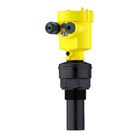
• Housing cover, optionally available with display and adjustment module PLICSCOM The components are available in different versions. Fig. 1: VEGASON 61 - version with plastic housing Housing cover with integrated PLICSCOM (optional) Housing with electronics, optionally available with plug connector 3 Process fitting with transducer VEGASON 61 • Foundation Fieldbus... -
Page 8: Principle Of Operation
• Software version ≤ 3.8 Principle of operation Application area VEGASON 61 is an ultrasonic sensor for continuous level measure- ment. It is suitable for liquids and solids in virtually all industries, particularly in the water and waste water industry. Functional principle The transducer of the ultrasonic sensor transmits short ultrasonic pulses to the measured product. These pulses are reflected by... -
Page 9: Packaging, Transport And Storage
It can be inserted into the sensor and removed at any time. You can find further information in the operating instructions "Display and adjustment module PLICSCOM" (Document-ID 27835). VEGACONNECT The interface adapter VEGACONNECT enables the connection of communication-capable instruments to the USB interface of a PC. For parameter adjustment of these instruments, an adjustment software such as PACTware with VEGA-DTM is required. VEGASON 61 • Foundation Fieldbus... - Page 10 3 Product description You can find further information in the operating instructions "Interface adapter VEGACONNECT" (Document-ID 32628). VEGADIS 81 The VEGADIS 81 is an external display and adjustment unit for VEGA plics sensors. ® For sensors with double chamber housing the interface adapter "DISADAPT" is also required for VEGADIS 81.
-
Page 11: Mounting
Prior to setup you have to replace these protective caps with ap- proved cable glands or close the openings with suitable blind plugs. Reference plane for The reference plane for the measuring range is the lower edge of the measuring range transducer. Make sure that a minimum distance from the reference plane - the so-called dead zone, in which measurement is not possible - is VEGASON 61 • Foundation Fieldbus... -
Page 12: Mounting Instructions
This influences the measuring result, particularly if the level is very low. With pressures under -0.2 bar (-20 kPa) you should use a different measuring principle, e.g. radar or guided microwave. Mounting instructions Screwing in Screw VEGASON 61 into the mounting socket with an appropriate spanner applied to the hexagon of the process fitting. Max. torque see chapter "Technical data". VEGASON 61 • Foundation Fieldbus... - Page 13 In vessels with conical bottom it can be advantageous to mount the sensor in the center of the vessel, as measurement is then possible down to the lowest point of the vessel bottom. VEGASON 61 • Foundation Fieldbus...
- Page 14 10 mm (0.394 in) out of the socket. Fig. 7: Recommended socket mounting If the reflective properties of the medium are good, you can mount VEGASON 61 on sockets which are higher than the length of the transducer. You will find recommended values for socket heights in the following illustration. The socket end should be smooth and burr-free, if possible also rounded.
- Page 15 "clear view" to the measured product. In case of existing vessel installations, a false echo storage should be carried out during setup. VEGASON 61 • Foundation Fieldbus...
- Page 16 Fig. 11: Cover flat, large-area profiles with deflectors Agitators If there are agitators in the vessel, a false signal storage should be carried out with the agitators in motion. This ensures that the interfer- ing reflections from the agitators are saved with the blades in different positions. Fig. 12: Agitators Do not mount the instruments in or above the filling stream. Make sure Inflowing medium that you detect the product surface, not the inflowing product. VEGASON 61 • Foundation Fieldbus...
- Page 17 Standpipe measurement By using a standpipe (surge or bypass tube), the influence of vessel installations, foam generation and turbulence is excluded. Standpipes must extend all the way down to the requested min. level, as measurement is only possible within the tube. VEGASON 61 • Foundation Fieldbus...
- Page 18 Fig. 14: Standpipe in the tank Vent hole: ø 5 … 10 mm (0.197 … 0.394 in) VEGASON 61 can be used from tube diameters of 40 mm (1.575 in). Avoid large gaps and thick welding joints when connecting the tubes.
-
Page 19: Connecting To Power Supply
The cable screens to the power supply unit and to the next distributor must be connected to each other and also connected to ground potential via a ceramic capacitor (e.g. 1 nF, 1500 V). The low frequency potential equalisation currents are thus suppressed, but the protective effect against high frequency interference signals remains. VEGASON 61 • Foundation Fieldbus... -
Page 20: Connection Procedure
9. Check the hold of the wires in the terminals by lightly pulling on them 10. Connect the screen to the internal ground terminal, connect the outer ground terminal to potential equalisation VEGASON 61 • Foundation Fieldbus... -
Page 21: Wiring Plan, Single Chamber Housing
Fig. 16: Material versions, single chamber housing Plastic Aluminium Stainless steel, precision casting Stainless steel, electro-polished Filter element for air pressure compensation of all material versions. Blind plug with version IP 66/IP 68, 1 bar for Aluminium and stainless steel VEGASON 61 • Foundation Fieldbus... -
Page 22: Wiring Plan, Double Chamber Housing
Wiring plan Display I 2 C Fig. 18: Wiring plan, single chamber housing Voltage supply, signal output Wiring plan, double chamber housing The following illustrations apply to the non-Ex as well as to the Ex-ia version. VEGASON 61 • Foundation Fieldbus... - Page 23 Electronics compartment Typ: Display I ² C 5 6 7 8 Fig. 20: Electronics compartment, double chamber housing Simulation switch ("on" = simulation mode) Connection for VEGACONNECT (I²C interface) Internal connection cable to the connection compartment VEGASON 61 • Foundation Fieldbus...
-
Page 24: Wiring Plan - Version Ip 66/Ip 68, 1 Bar
Voltage supply, signal output Wiring plan - version IP 66/IP 68, 1 bar Wire assignment, con- nection cable Fig. 23: Wire assignment, connection cable brown (+) and blue (-) to power supply or to the processing system Shielding VEGASON 61 • Foundation Fieldbus... -
Page 25: Switch-On Phase
5 Connecting to power supply Switch-on phase Switch-on phase After VEGASON 61 is connected to voltage supply or after voltage recurrence, the instrument carries out a self-check for approx. 30 seconds. The following steps are carried out: • Internal check of the electronics •... -
Page 26: Set Up With The Display And Adjustment Module Plicscom
The display and adjustment module is powered by the sensor, an ad- ditional connection is not necessary. Fig. 24: Insert display and adjustment module Note: If you intend to retrofit the instrument with a display and adjustment module for continuous measured value indication, a higher lid with an inspection glass is required. VEGASON 61 • Foundation Fieldbus... -
Page 27: Adjustment System
By pushing the keys longer than 1 s the change will be continuously. By pushing the [OK] and [ESC] keys simultaneously for more than 5 s, a return to the basic menu is caused. The menu language is then switched over to "English". VEGASON 61 • Foundation Fieldbus... -
Page 28: Setup Steps
Basic adjustment - Min. adjustment 1. Move from the measured value display to the main menu by pushing [OK]. ▶ Basic adjustment Display Diagnostics Service Info 2. Select the menu item "Basic adjustment" with [->] and confirm with [OK]. Now the menu item "Min. adjustment" is displayed. VEGASON 61 • Foundation Fieldbus... - Page 29 Through this additional selection, the sensor is adapted perfectly to the product and measurement reliability, particularly in products with poor reflective properties, is considerably increased. Enter the requested parameters via the appropriate keys, save your settings and jump to the next menu item with the [->] key. VEGASON 61 • Foundation Fieldbus...
- Page 30 Display - Displayed value Radar, guided microwave and ultrasonic sensors deliver the following measured values: • SV1 (Secondary Value 1): Percentage value after the adjustment • SV2 (Secondary Value 2): Distance value before the adjustment • PV (Primary Value): Linearised percentage value • AI FB1 (Out) VEGASON 61 • Foundation Fieldbus...
- Page 31 Diagnosis - Curve pres- A comparison of the echo curve and the false echo curve allows a entation more detailled evaluation of measurement reliability. The selected curve is updated continuously. With the [OK] key, a submenu with zoom functions is opened. VEGASON 61 • Foundation Fieldbus...
- Page 32 Check the distance to the product surface, because if an incorrect (too large) value is entered, the existing level will be saved as a false signal. The level would then no longer be detectable in this area. VEGASON 61 • Foundation Fieldbus...
- Page 33 The menu item "Extended setting" offers the possibility to optimise Service - Extended set- ting VEGASON 61 for applications in which the level changes very quickly. To do this, select the function "Quick level change > 1 m/min.". Extended setting quick level change > 1 m/min.
- Page 34 Deutsch • English • Français • Espanõl • Pycckuu • Italiano • Netherlands • Japanese • Chinese Depending on the sensor type, see chapter "Technical data". Special parameters are parameters which are set customer-specifically on the service level with the adjustment software PACTware. VEGASON 61 • Foundation Fieldbus...
- Page 35 Select menu items and show data • Read data from the sensor into the display and adjustment mod- ule. Menu section, info Info In this menu item the most important sensor information can be displayed: • Instrument type • Serial number: 8-digit number, e.g. 12345678 VEGASON 61 • Foundation Fieldbus...
-
Page 36: Menu Schematic
< max. 32 characters > • Sensor details, e.g. approval, process fitting, seal, measuring cell, measuring range, electronics, housing, cable entry, plug, cable length etc. Sensor characteristics Display now? Menu schematic Information: Depending on the version and application, the highlighted menu windows may not always be available. VEGASON 61 • Foundation Fieldbus... - Page 37 Service Info Peak value indicator Meas. reliability Curve selection Echo curve Distance min.: 0.580 m(d) 36 dB Dist. max.: 16.785 m(d) Sensor status Echo curve Presentation of the echo curve T-max.: 30.6 °C T-min.: 4.5 °C VEGASON 61 • Foundation Fieldbus...
-
Page 38: Saving The Parameter Adjustment Data
They are thus available for multiple use or service purposes. If VEGASON 61 is equipped with a display and adjustment module, the most important data can be read out of the sensor into the display and adjustment module. -
Page 39: Set Up With Pactware And Other Adjustment Programs
Sensor VEGACONNECT exter- nally TWIST Fig. 28: Connection via VEGACONNECT externally I²C bus (com.) interface on the sensor I²C connection cable of VEGACONNECT VEGACONNECT USB cable to the PC Necessary components: • VEGASON 61 • PC with PACTware and suitable VEGA DTM VEGASON 61 • Foundation Fieldbus... -
Page 40: Parameter Adjustment With Pactware
Saving/printing the project as well as import/export functions are also part of the standard version. In the full version there is also an extended print function for complete project documentation as well as a save function for measured value VEGASON 61 • Foundation Fieldbus... -
Page 41: Parameter Adjustment With Ams
For VEGA sensors, instrument descriptions for the adjustment program AMS™ are available as DD. The instrument descriptions are already implemented in the current version of AMS™. For older ver- sions of AMS™, a free-of-charge download is available via Internet. Go via www.vega.com and "Downloads" to the item "Software". Saving the parameter adjustment data It is recommended to document or save the parameter adjustment data. That way they are available for multiple use or service purposes. -
Page 42: Maintenance And Fault Rectification
24 hour service hotline Should these measures not be successful, please call in urgent cases the VEGA service hotline under the phone no. +49 1805 858550. The hotline is manned 7 days a week round-the-clock. Since we offer this service worldwide, the support is only available in the English language. The service is free, only standard call charges are incurred. -
Page 43: Exchanging The Electronics Module
Ex approval may be used. If there is no electronics module available on site, one can be ordered from the VEGA agency serving you. Sensor serial number The new electronics module must be loaded with the settings of the sensor. -
Page 44: Software Update
Voltage supply • Interface adapter VEGACONNECT • PC with PACTware • Current instrument software as file You can find the current instrument software as well as detailed information on the procedure under "www.vega.com/downloads" and "Software". Caution: Instruments with approvals can be bound to certain software versions. Therefore make sure that the approval is still effective after a software update is carried out. You can find detailed information at www.vega.com/downloads and "Approvals". -
Page 45: Vegason 61 • Foundation Fieldbus
These may be used only for privately used products according to the WEEE directive. Correct disposal avoids negative effects on humans and the environ- ment and ensures recycling of useful raw materials. Materials: see chapter "Technical data" If you have no way to dispose of the old instrument properly, please contact us concerning return and disposal. VEGASON 61 • Foundation Fieldbus... -
Page 46: Supplement
Input variable Measured variable distance between lower edge of the transducer and product surface Measuring range Ʋ Liquids up to 5 m (16.4 ft) Ʋ Bulk solids up to 2 m (6.562 ft) Dead zone 0.25 m (0.82 ft) VEGASON 61 • Foundation Fieldbus... -
Page 47: Ambient Conditions
2 m (6.562 ft) 3 m (9.843 ft) 4 m (13.123 ft) 5 m (16.404 ft) -4 mm (-0.157 in) -10 mm (-0.394 in) Fig. 30: Deviation VEGASON 61 Influence of the ambient temperature to the sensor electronics Average temperature coefficient of the 0.06 %/10 K zero signal (temperature error) Ambient conditions Ambient, storage and transport tempera- -40 … +80 °C (-40 … +176 °F) - Page 48 Ʋ Wire resistance < 0.036 Ω/m (0.011 Ω/ft) Ʋ Tensile strength < 1200 N (270 lbf) Ʋ Standard length 5 m (16.4 ft) Ʋ Max. length 1000 m (3280 ft) Tested according to the guidelines of German Lloyd, GL directive 2. Depending on the version M12 x 1, according to DIN 43650, Harting, 7/8" FF. VEGASON 61 • Foundation Fieldbus...
- Page 49 NEMA 6P IP 68 (1 bar) NEMA 6P Double chamber IP 66/IP 67 NEMA 4X IP 66/IP 68 (0.2 bar) NEMA 6P IP 68 (1 bar) NEMA 6P Stainless steel, electro- Single chamber IP 66/IP 68 (0.2 bar) NEMA 6P polished VEGASON 61 • Foundation Fieldbus...
-
Page 50: Foundation Fieldbus
For that reason the associated approval documents of these instruments have to be carefully noted. They are part of the delivery or can be downloaded under www.vega.com via "VEGA Tools" and "Instrument search" as well as via "Downloads" and "Approvals". - Page 51 Channel = 1: Primary Value Channel = 2: Secondary Value 1 Channel = 3: Secondary Value 2 AI 3 Channel = 4: Temperature Fig. 31: VEGASON 61 measured value processing Diagram, adjustment The following illustration shows the function of the adjustment: Secondary_value_1 cal_level_hi...
- Page 52 SUB_DEVICE_NUMBER • SENSOR_ELEMENT_TYPE • display_source_selector – Selects the type of value, which is displayed on the indicating and adjustment module • max_peak_sensor_value – Holds the maximum sensor value. Write access resets to current value. Unit derives from 'Sen- sor_range.unit' • min_peak_sensor_value – Holds the minimum sensor value. Write access resets to current value. Unit derives from 'Sen- sor_range.unit' • CAL_POINT_HI – Min./max.-adjustment: Upper calibrated point of the sensor. It refers to 'Cal_level_hi'. The unit is defined in 'Sensor_range.unit'hi VEGASON 61 • Foundation Fieldbus...
- Page 53 • first_echo_factor – Set up to suit the process conditions • pulse_velocity_correction – Set up to suit the process conditions • echo_quality – Signal/Noise ratio • empty_vessel_curve_corr_dist – Distance from the sensor to the product surface. Unit derives from 'Sensor_range.unit' • empty_vessel_curve_corr_op_code VEGASON 61 • Foundation Fieldbus...
- Page 54 – Update, create new or delete the empty vessel curve • sound_velocity – Set up to suit the process conditions • sound_velocity_unit – Unit code of 'Sound_velocity' • Temperature – Process temperature. Selected as input to AIFB by setting 'Channel' = 4. Unit derives from 'Temperature.unit' • temperature_unit – Unit code of 'Temperature', 'Max./Min._peak_temperature_value' • max_peak_temperature_value – Holds the maximum process temperature. Write access resets to current value. Unit derives from 'Temperature.unit' • min_peak_temperature_value – Holds the minimum process temperature. Write access resets to current value. Unit derives from 'Temperature.unit' VEGASON 61 • Foundation Fieldbus...
-
Page 55: Dimensions
9 mm/0.35 in higher Plastic housing (IP 66/IP 67) Aluminium housing Aluminium double chamber housing Stainless steel housing, electropolished Stainless steel housing - precision casting Stainless steel double chamber housing - precision casting VEGASON 61 • Foundation Fieldbus... - Page 56 1½"NPT ø 39mm ") ø 74mm ") Fig. 35: VEGASON 61 Dead zone: 0.25 m (0.82 ft) Measuring range: with liquids up to 5 m (16.4 ft), with solids up to 2 m (6.562 ft) VEGASON 61 • Foundation Fieldbus...
- Page 57 Les lignes de produits VEGA sont globalement protégées par des droits de propriété intellec- tuelle. Pour plus d'informations, on pourra se référer au site www.vega.com. VEGA lineas de productos están protegidas por los derechos en el campo de la propiedad indus- trial. Para mayor información revise la pagina web www.vega.com.
- Page 58 Notes VEGASON 61 • Foundation Fieldbus...
- Page 59 Notes VEGASON 61 • Foundation Fieldbus...
- Page 60 Subject to change without prior notice © VEGA Grieshaber KG, Schiltach/Germany 2015 VEGA Grieshaber KG Phone +49 7836 50-0 Am Hohenstein 113...
Need help?
Do you have a question about the VEGASON 61 and is the answer not in the manual?
Questions and answers